
Related Manuals for AMX DGX1600-ENC


Summary of Contents for AMX DGX1600-ENC
- Page 1 H ARD WARE R E F E RE NCE MA N U A L ENOVA D GX 1 0 0 S E R IE S DIGIT AL ME D IA S W I TCH E RS DGX800-ENC, DGX1600-ENC, DGX3200-ENC, DGX6400-ENC...
-
Page 2: Important Safety Instructions
COPYRIGHT NOTICE AMX© 2017, all rights reserved. No part of this publication may be reproduced, stored in a retrieval system, or transmitted, in any form or by any means, electronic, mechanical, photocopying, recording, or otherwise, without the prior written permission of AMX. Copyright protection claimed... - Page 3 (recast) Directive 2012/19/EU; European Union Eco-Design Directive 2009/125/EC; European Union Registration, Evaluation, Authorization and Restriction of Chemicals (REACH) Regulation (EC) 1907/2006. You may obtain a free copy of the Declaration of Conformity by visiting http://www.amx.com/techcenter/certifications.asp. WEEE NOTICE This appliance is labeled in accordance with European Directive 2012/19/EU concerning waste of electrical and electronic equipment (WEEE).
-
Page 4: Esd Warning
Anyone performing field maintenance on AMX equipment should use an appropriate ESD field service kit complete with at least a dissipative work mat with a ground cord and a UL listed adjustable wrist strap with another ground cord. - Page 5 CHINA MARKINGS (ONLY FOR INSTALLATIONS LOCATED IN CHINA) 2000 2000 2000 This symbol denotes that the device is not to be used at altitudes exceeding 2000 meters. This symbol denotes that the device is only to be used in climate regions that are not-tropical. Hardware Reference Manual –...
-
Page 6: Table Of Contents
Contents CONTENTS Product Overview and General Specifications ............11 Applicability Notice........................11 Product Notes..........................13 Common Applications ....................... 15 Front View..........................16 Rear View........................... 17 Integrated NetLinx NX Master Functionality................24 Enova DGX 800 – General Specifications .................. 28 Enova DGX 1600 – General Specifications ................29 Enova DGX 3200 –... - Page 7 Contents Troubleshooting and Technical Support................... 61 Enova DGX HDMI Boards ..................62 Enova DGX HDMI Boards – Specifications ................. 63 Enova DGX 4K HDMI Boards – Specifications................65 Attaching Cables ........................70 HDCP Support on Enova DGX Switchers..................70 InstaGate Pro® Technology ..................... 72 Troubleshooting Video ......................
- Page 8 Contents Fiber Optic Transceiver LEDs in Duplex and Simplex Hardware ..........120 Duplex Hardware Directional Mode Configuration..............121 Configuring DXLink Endpoints for Communication with a Master .......... 122 Auto-setup..........................123 Serial Data Transfer and IR Flow Control................124 Replacing an SFP+ Fiber Optic Transceiver ................125 DXLink Fiber Troubleshooting ....................
- Page 9 Contents System Configuration Interface Overview ................163 Switching Page ........................164 Configuration Page........................167 Status Page..........................177 NetLinx® Studio ....................179 Installing NetLinx Studio and Connecting to a Master ............179 Confirming Board Versions ..................... 180 Enabling Control Characters in a Terminal or Telnet Session ..........180 Integrated Master –...
- Page 10 Contents Appendix B – Replacing Battery on CPU ............... 240 Applicability..........................240 Removing and Installing ......................240 Appendix C – DGX_SHELL Commands ..............243 Overview DGX_SHELL Commands ................... 243 Basic DGX_SHELL Commands....................247 Appendix D – Telnet Communication with Enova DGX 100 Series CPU ....255 Overview ..........................
-
Page 11: Product Overview And General Specifications
DGX-O-DXL * Enova DXLink Twisted Pair Boards must be used in conjunction with DXLink Twisted Pair Transmitters and Receivers or other AMX DXLink signal management solutions. For model numbers of compatible Transmitters and Receivers, see page 83. For system setup information, see page 87. - Page 12 * Enova DXLink Twisted Pair 4K Boards must be used in conjunction with DXLink Twisted Pair 4K Transmitters and Receivers or other AMX DXLink signal management solutions. For model numbers of compatible Transmitters and Receivers, see page 97. For system setup information, see page 101.
-
Page 13: Product Notes
AxLink Control port (4-pin captive wire connector) for direct control of AxLink devices Product Support AMX Limited Lifetime Warranty included (see www.amx.com) 24-hour technical support Hardware Reference Manual – Enova DGX 100 Series Digital Media Switchers... - Page 14 Integrated NetLinx NX Master (NetLinx NX Controller) with control via the System Configuration interface; server (public LAN) connection through the LAN 100/1000 port on the CPU Compatible with a number of AMX control devices (for NetLinx control programming information, see page 181 and the manual for the specific AMX control device) Front control panel (standard on all enclosures) ...
-
Page 15: Common Applications
Product Overview and General Specifications Common Applications The Enova DGX 100 Series is ideal for dramatically simplifying AV control and distribution in large spaces such as lecture halls, auditoriums, hotel ballrooms, casinos, museums, and stadiums/arenas. In addition, it is ideally suited for multi-room or configurable room applications, where multiple collaboration spaces share a single Enova DGX for control. -
Page 16: Front View
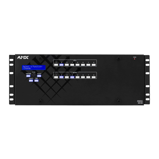
Product Overview and General Specifications Front View The enclosure, which is the structural basis of an Enova DGX Switcher, can be controlled using an external controller, control software, the integrated NetLinx NX Central Control Processor’s System Configuration interface, or standard front control panel. For additional information on control options, see page 33. -
Page 17: Rear View
Product Overview and General Specifications Rear View Enclosure The enclosure’s appearance, as viewed from the rear, will vary depending on the number and types of input, output, and expansion boards present. The Enova DGX 800 enclosure in FIG. 3 is fully loaded for 8x8 switching. The Enova DGX 1600 enclosure in FIG. 4 is fully loaded for 16x16 switching. - Page 18 Product Overview and General Specifications Enova DGX 3200 Enova DGX 3200 Rear View NOTE: If the enclosure has any empty input Output boards (up to 8) Input boards (up to 8) or output board slots (which are numbered for additional boards), they can be used to expand the system.
- Page 19 ID Pushbutton – for selecting static IP or DHCP, resetting the factory defaults, and restoring the factory firmware image (see page 59) AxLink port – for supporting AMX AxLink devices (see page 57) Config DIP switch (2-position toggles) – for setting the Program Run Disable (PRD) mode (see page 60) ...
-
Page 20: Power Supply Units
Product Overview and General Specifications Power Supply Units Each of the power supply units on the rear of the enclosure (FIG. 8) has a power receptacle that will accept all major international standard power sources. (US power cords are included with all enclosures shipped within the US.) Maximum power specifications are provided on the power supply receptacles. - Page 21 Product Overview and General Specifications Enova DGX 800 Numbering plate Output boards Input boards DVI Board DXLink Fiber Board HDMI Board DXLink Twisted Pair Board FIG. 9 HDMI and DXLink Twisted Pair Input Boards and DVI, DXLink Fiber Output Boards shown Enova DGX 800 enclosures have four horizontal I/O board slots (two slots each for input and output boards with four connectors each), allowing for a maximum configuration of 8x8.
- Page 22 Product Overview and General Specifications Enova DGX 6400 Enova DGX 6400 boards Numbering plate Input boards located in upper 16 board slots 8 Right 8 Left Inputs Inputs 2 DXLink Fiber SM-D 4 DXLink Twisted Pair 2 DXLink Fiber MM-D 4 DVI 4 HDMI Output boards located in upper 16 board slots...
- Page 23 Product Overview and General Specifications Connectors and Signal Types Connector Supported Signals HDMI • HDMI with or without HDCP or embedded digital audio • DVI-D (single link) with or without HDCP (adapter cable required) • DVI-D (single link) with or without HDCP •...
-
Page 24: Integrated Netlinx Nx Master Functionality
Product Overview and General Specifications Audio Insert/Extract Board The Enova DGX 800/1600/3200 holds up to two AIE expansion boards. The Enova DGX 6400 holds up to eight AIE expansion boards. Embedded audio signals switch with the video channels. Through the use of the Audio Insert/Extract Board, embedded audio can be extracted and external audio matrix switches can be executed (using a separately purchased audio matrix switcher like the Precis DSP) and then reinserted post-switch on the output side. - Page 25 No other indications are provided for which network is in use, only whether the socket is successfully created. Integrated NetLinx NX Master Features The integrated NetLinx NX Master supports the following features: Automatic configuration of AMX devices via ICS LAN (private network) Link-local fallback in DHCP mode (IPv4 only) ...
- Page 26 Product Overview and General Specifications ID Pushbutton The ID Pushbutton functions performed depend on when and for how long the ID Pushbutton is pressed and held. The integrated Master includes ID Pushbutton functionality for selecting a static or DHCP address, performing a factory default reset, and restoring the factory firmware image (for instructions, see page 59).
- Page 27 NOTE: For further information about using Telnet commands and a complete list of commands available for NetLinx NX Central Controllers, see the “WebConsole & Programming Guide – NX-Series Controllers” at www.amx.com. NetLinx NX Telnet Commands for the Integrated NetLinx NX Master...
-
Page 28: Enova Dgx 800 - General Specifications
Product Overview and General Specifications Enova DGX 800 – General Specifications General Specifications Parameter Value Approvals UL 60950-1, CSA 60950-1, IEC 60950-1, CE EN 60950-1, CE EN 55022 Class A, CE EN 55024, FCC CFR Title 47 Part 15 Subpart B Class A, ICES-003 Class A, RoHS, WEEE AC Power per Supply 100-240 +/-10% VAC single phase, 50/60 Hz... -
Page 29: Enova Dgx 1600 - General Specifications
Product Overview and General Specifications Enova DGX 1600 – General Specifications General Specifications Parameter Value Approvals UL 60950-1, CSA 60950-1, IEC 60950-1, CE EN 60950-1, CE EN 55022 Class A, CE EN 55024, FCC CFR Title 47 Part 15 Subpart B Class A, ICES-003 Class A, RoHS, WEEE AC Power per Supply 100-240 +/-10% VAC single phase, 50/60 Hz... -
Page 30: Enova Dgx 3200 - General Specifications
• Solecis 5x1 4K Multi-Format Digital Switcher with DXLink Output *Use the Enova DGX Configuration Tool located at www.AMX.com/enova to determine the power requirements of a configuration and whether any of the DXLink Transmitters or Receivers should be powered with the local power supply to maintain power supply redundancy in the Enova DGX 32 enclosure. -
Page 31: Enova Dgx 6400 - General Specifications
Product Overview and General Specifications Enova DGX 6400 – General Specifications General Specifications Parameter Value Approvals UL 60950-1, CSA 60950-1, IEC 60950-1, CE EN 60950-1, CE EN 55022 Class A, CE EN 55024, FCC CFR Title 47 Part 15 Subpart B Class A, ICES-003 Class A, RoHS, WEEE AC Power per Supply 100-240 +/-10% VAC single phase, 50/60 Hz... -
Page 32: Enova Dgx - Netlinx And Control Specifications
For a list of HID devices which have been tested and found to be working well with the latest firmware, please view the document, “DXLink HID Keyboard and Mouse Supported Devices” at www.amx.com on the product page for your DXLink Fiber Receiver or DXLink Twisted Pair Receiver. -
Page 33: Configuration Information And Control Options
SEND_COMMANDs – The Enova DGX Switcher can be controlled using AMX SEND_COMMANDs. ICSP is the primary protocol for all system level messaging on integrated NetLinx NX Central Control Processors and is a peer-to-peer protocol used for both Master-to-Master and Master-to-device communications. - Page 34 The Enova DGX Switcher is compatible with a number of AMX control devices via Native NetLinx communication. For control programming information, see the chapter on ICSP commands on page 181 and the manual for the specific AMX control device. BCS (Basic Control Structure) Protocol The Enova DGX Switcher can be controlled with an external serial controller using BCS* protocol, a command language for programming control operations and for diagnostic purposes.
-
Page 35: Enova Dgx 100 Series And Enova Dgx 8/16/32/64 Differences
Product Overview and General Specifications Enova DGX 100 Series and Enova DGX 8/16/32/64 Differences The Enova DGX 100 Series has incorporated a number of technological advancements which resulted in changes that may be of interest to users of previous Enova DGX products. In order to assist these users, we have included the table below which captures some of the main system differences (highlighted cells represent changes that may affect programming code in existing systems). - Page 36 Product Overview and General Specifications Enova DGX 100 Series and Enova DGX 8/16/32/64 Differences Compatibility and Hardware Support System Compatibility Please refer to the shipping document: Requires kit v3.0.10 or later for new 100 Series feature support. Older I/O cards added to a new Enova DGX Input/Output board and Endpoint system must be upgraded.
-
Page 37: System Diagnostic Options
The Status page in the System Configuration interface (Switcher/Status) displays status for the power supplies, fans, CPU, I/O boards, and expansion boards (see page 177). For complete information, see the WebConsole & Programming Guide – NetLinx NX Central Controllers at www.amx.com. DGX_SHELL Commands The Enova DGX 100 Series supports a number of shell (command-line interpreter) commands for a variety of functions, both basic and advanced (see “Appendix C”... -
Page 38: Installation And Setup
Installation and Setup Installation and Setup DXLink Fiber Boards IMPORTANT: If the Enova DGX Switcher contains Enova DGX DXLink Fiber Boards, be sure to read all of the safety information for laser products in this chapter and in the DXLink Fiber Boards chapter. WARNING: DXLink Fiber units use laser transceivers, which are Class 1 Eye Safe per IEC 60825-1/CDRH requirements. -
Page 39: Unpacking
□ Collect all documentation. NOTE: Please save the original shipping container and packing materials. AMX is not responsible for damage caused by insufficient packing during return shipment to the factory. Shipping boxes are available; contact your AMX representative for details. -
Page 40: Rack Installation And System Setup
Installation and Setup Options for System Setup with DXLink Twisted Pair 4K The following table contains the options in an Enova DGX Switcher for using DXLink Twisted Pair 4K Input and Output Boards in conjunction with DXLink Twisted Pair 4K Transmitters and Receivers. System Setup Options –... -
Page 41: Installation Procedure
Installation and Setup Safety Recommendations for Laser Products IMPORTANT: No user serviceable parts are included inside Enova DGX Switchers; service should only be done by qualified personnel. CAUTION: Use of controls or adjustments or performance of procedures other than those specified herein may result in hazardous radiation exposure. - Page 42 Installation and Setup Installing an Enova DGX 6400 Enclosure This procedure applies to starting the installation of an Enova DGX 6400. For either completing the Enova DGX 6400 installation or installing an Enova DGX 800/1600/3200, see the instructions on the next page. To start installation of Enova DGX 6400 enclosure in rack (requires 3 people minimum): IMPORTANT: Do not use the board extractor handles to lift the enclosure or to maneuver it into place.
- Page 43 Installation and Setup Installing an Enova DGX 100 Series Enclosure For installing the Enova DGX 800/1600/3200, all of the steps below are required. For the Enova DGX 6400, the procedure above must be completed first, after which only Steps 4 through Step 11 below are required). To install and setup an Enova DGX Switcher: IMPORTANT: Installation of the Enova DGX 3200 requires a minimum of two people for Step 3;...
-
Page 44: Installation Options
Installation and Setup Installation Options Additional installation tasks may include the following:. Attaching an AxLink Device – page 57 Using the ID Pushbutton – page 59 Setting PRD Mode – page 60 Establishing Telnet connection with the CPU – page 255 ... -
Page 45: Attaching Video Input And Output Cables
Installation and Setup Attaching Video Input and Output Cables Input and output connectors are the attachment points for source and destination devices that connect to the system. Enova DGX 800/1600 Viewed from the rear of the enclosure, the Enova DGX 800/1600 input boards (for attaching sources) are on the left, and the output boards (for attaching destinations) are on the right. - Page 46 Installation and Setup Enova DGX 6400 The Enova DGX 6400 has input boards at the top of the enclosure’s rear and output boards below. Enclosures have 32 horizontal board slots (16 slots each for the input and the output boards, with 4 connectors per board), ...
-
Page 47: Wiring Audio Inputs And Outputs
Installation and Setup Wiring Audio Inputs and Outputs Enova DGX Switchers can include the following audio expansion boards: Dante Audio Switching Boards (ASB-DAN), Audio Switching Boards (ASB) or Audio Insert/Extract (AIE) Boards. Audio expansion boards work in conjunction with HDMI, 4K HDMI, DVI, DXLink Twisted Pair 4K, DXLink Twisted Pair, and DXLink Fiber Boards. - Page 48 Installation and Setup Enova DGX 6400 – To provide adequate power for an N+1 redundant application, connect each of the power supplies to its own circuit. Circuit Breaker 2 Circuit Breaker 1 FIG. 24 Power setup for complete redundancy on Enova DGX 3200 CAUTION: We recommend attaching all power cords to a surge protector and/or an AC line conditioner.
- Page 49 Installation and Setup Enova DGX 3200 power supplies FIG. 26 Attach power cables to both power receptacles (Enova DGX 3200 shown) Enova DGX 6400 power supplies FIG. 27 Attach power cables to all four power receptacles (Enova DGX 6400 shown) Plug the other end of each power cord into its power source (if using a power strip, turn on the power strip).
-
Page 50: Redundant Power Supply (Rps)
Installation and Setup Indicator Lights at Startup When the enclosure powers up, the indicator LEDs respond as follows: Enova DGX LED Indicators Indicates Normal Display Cautionary Front Power System power status Constant green Constant red: one power supply is not working Enova DGX 6400 only - •... -
Page 51: System Setup For Using The Integrated Netlinx Nx Master
Installation and Setup System Setup for Using the Integrated NetLinx NX Master The Enova DGX 100 Series Switcher has an integrated NetLinx NX Central Control Processor (Master) that establishes its public LAN (Local Area Network) connection through the LAN 100/1000 port on the CPU. The Master provides a System Configuration interface that allows you to make various configuration settings via a web browser on any PC connected to the public LAN. - Page 52 Installation and Setup ICS LAN 10/100 and LAN 100/1000 Indicator LEDs RJ-45 Indicator LEDs ICS LAN 10/100 port LAN 100/1000 port L/A (green) LED SPD (yellow) LED FIG. 29 ICS LAN 10/100 and LAN 100/1000 port LED indicators Cable Requirements and Pinouts □...
- Page 53 Installation and Setup T568B The following table lists the pinouts, signals, and pairing for the Ethernet connector when wired for straight-through cable according to T568B. T568B Pairing T568B Signals Connections Pairing Color 1--------1 1--------2 Orange - White 2--------2 Orange 3--------3 3--------6 Green - White No connection...
-
Page 54: Confirming Board Versions
IP address changing at power up, you can change the DHCP address to a static IP address (see the “WebConsole & Programming Guide – NetLinx NX Central Controllers” at www.amx.com). The integrated Master’s IP address is available via the control panel at Setup Options/Master Info/IP Address. -
Page 55: System Configuration Interface Setup
HTML5 features NOTE: User experience may differ due to browser support for HTML5. Setting up the system to use AMX’s System Configuration interface requires completing the following three items. Detailed instructions for each item are given. -
Page 56: Audio Control And Signal Processing Options
Mute – page 226 BCS Commands Volume, input gain, and mute – See the BCS (Basic Control Structure) Protocol Programming Guide at www.amx.com. Establish Serial Communication with a PC via the Program Port Program Port The Enova DGX Switcher’s integrated NetLinx NX Master is equipped with a low-speed USB connection labeled “Program.” Use the provided USB mini-AB adapter cable (CA1090-541) to establish a connection between the Program port on the enclosure and the PC’s USB port. -
Page 57: Attaching An Axlink Device
The CPU board has an AxLink port and an adjacent AxLink LED on its right. The AxLink port is a 4-pin mini-Phoenix (female) captive-wire connector. This port allows the integrated Master to support AMX AxLink devices. The AxLink port can be used to supply power to downstream AxLink-compatible devices as long as the power required does not exceed 2 Amps. - Page 58 For NetLinx programming purposes, each AxLink device must be assigned a unique number to locate that device on the bus. The range for AxLink device numbers is 1-255. AMX best practices requires assigning device numbers in three groups: Axcess Control Cards: 1 - 95 ...
-
Page 59: Using The Id Pushbutton
The functions performed depend on when and for how long the ID Pushbutton is pressed and held. NOTE: ID Pushbutton functions can also be implemented using Telnet commands (see the “WebConsole & Programming Guide – NetLinx NX Central Controllers” at www.amx.com). Toggling Between DHCP and Static IP Addressing To select static IP or DHCP: Verify that the Master is not currently booting*. -
Page 60: Program Run Disable (Prd) Mode
Installation and Setup Program Run Disable (PRD) Mode IMPORTANT: The information in this section is not applicable when the system is running under normal operating conditions. The PRD mode should only be used if the resident NetLinx program is causing inadvertent communication and/or control problems. If the procedure is necessary, use NetLinx Studio (v4.0 or later) to resolve the communication and/or control problems with the resident NetLinx program. -
Page 61: Troubleshooting And Technical Support
AMX representative or technical support. Have the serial numbers for your system and any applicable AMX accessory devices ready (the numbers are normally located on the rear of the enclosure or accessory devices). We recommend recording your system’s serial numbers in an easily accessible location. -
Page 62: Enova Dgx Hdmi Boards
Enova DGX HDMI Boards Enova DGX HDMI Boards Applicability Notice This chapter pertains to Enova DGX HDMI Input Boards and HDMI Output Boards. FG1058-540 Input board FG1061-540 4K HDMI Input Board FG1058-550 Output board NOTE: Enova DGX 4K HDMI Boards feature a “4K” label beside the “IN”... -
Page 63: Enova Dgx Hdmi Boards - Specifications
Enova DGX HDMI Boards InstaGate Pro® and SmartScale® HDMI Boards are HDCP 1.4 compatible and feature InstaGate Pro Technology* for low-latency switching of HDCP protected content and support computer video up to 1920x1200 and HDTV up to 1080p. The HDMI Boards also support embedded audio, both linear PCM (stereo audio) and non-linear PCM (Dolby Digital, DTS, Dolby TrueHD, etc.). - Page 64 HDCP Support Yes, full matrix HDCP 1.4 support (includes any input to any or all outputs) • Key Management System • AMX HDCP InstaGate Pro® Technology • Key support up to 16 devices per output, independent of source device CEC Support...
-
Page 65: Enova Dgx 4K Hdmi Boards - Specifications
HDCP Support Yes, full matrix HDCP 1.4 support (includes any input to any or all outputs) • Key Management System • AMX HDCP InstaGate Pro® Technology • Key support up to 16 devices per output, independent of source device CEC Support... - Page 66 Enova DGX HDMI Boards HDMI Board EDID Resolutions Supported through Local DDC Standard and established timings are given in the tables following along with detailed timing blocks. NOTE: This section covers all of the default EDIDs for HDMI Input and Output Boards (not 4K HDMI Boards). In the System Configuration interface, the EDIDs contained in this section's tables are displayed in a single dropdown menu (General section, Preferred EDID menu) and VICs are differentiated by the presence of a “p”...
- Page 67 Enova DGX HDMI Boards HDMI CTA Video Information Code (VIC) Formats NOTE: CTA VIC formats for 4K HDMI Boards are located on page 69. VIC # Resolution Refresh Rate and Aspect Ratio VIC = 1 640x480p 59.94/60 Hz 4:3 VIC = 2 720x480p 59.94/60 Hz 4:3 VIC = 3...
- Page 68 Enova DGX HDMI Boards 4K HDMI Board EDID Resolutions Supported through Local DDC NOTE: This section covers all of the default EDIDs for 4K HDMI Boards. In the System Configuration interface, the EDIDs contained in this section's tables are displayed in a single dropdown menu (General section, Preferred EDID menu) and VICs are differentiated by the presence of a “p”...
- Page 69 Enova DGX HDMI Boards 4K HDMI CTA Video Information Code (VIC) Formats NOTE: CTA VIC formats for HDMI Boards are located on page 67. NOTE: The Short Video Descriptor (SVD) column describes the order of video preference. SVD # VIC # Resolution Refresh Rate and Aspect Ratio Notes...
-
Page 70: Attaching Cables
Enova DGX HDMI Boards Attaching Cables Viewed from the rear of the enclosure, the input boards (for attaching sources) are on the left, and the output boards (for attaching destinations) are on the right. Enova DGX 800/1600 – Input and output channel numbers correspond to the connectors and are located between the input and output boards. - Page 71 So even though the number of sinks each HDMI output on the switcher can handle is finite, the number of sinks can be unlimited if using AMX devices that support InstaGate Pro Technology.
-
Page 72: Instagate Pro® Technology
Enova DGX HDMI Boards ® InstaGate Pro Technology InstaGate Pro Technology eliminates latency (time required for authentication) in the switcher for HDCP negotiations with the displays in a system. The latency is typically experienced when HDCP authenticates HDMI source and destination devices every time a new switching combination between a source device and display occurs. -
Page 73: Troubleshooting Audio
Enova DGX HDMI Boards Troubleshooting Audio Before troubleshooting audio, it helps to understand how the system handles EDID information. The source reads and adapts to the pre-loaded EDID on the DGX HDMI input connector. The factory default EDID is set to support 2 channel L-PCM audio. This EDID can be modified by using one of the methods ... -
Page 74: Enova Dgx Dvi Boards
Enova DGX DVI Boards Enova DGX DVI Boards Applicability Notice This chapter pertains to the following DVI Input Board and Output Board for the Enova DGX Switcher: FG1058-600 Input board FG1058-610 Output board FIG. 40 DVI Input and DVI Output Boards Enova DGX 800 Enova DGX 800 enclosures hold up to four DVI Boards with four inputs or outputs per board. -
Page 75: Enova Dgx Dvi Boards - Specifications
Enova DGX DVI Boards ® ® InstaGate Pro and SmartScale DVI Boards meet HDCP Standards and support InstaGate Pro Technology. For information on HDCP functionality for DVI Boards, see “HDCP Support on Enova DGX Switchers” on page 70. DVI Input Boards provide EDID emulation support with plug-and-play information provided by the Enova DGX Switcher. ... - Page 76 HDCP Support Yes, full matrix HDCP support (includes any input to any or all outputs) • Key Management System • AMX HDCP InstaGate Pro® Technology • Key support up to 16 devices per output, independent of source device CEC Support...
- Page 77 Enova DGX DVI Boards EDID Resolutions Supported through Local DDC NOTE: This section covers all of the default EDIDs. In the System Configuration interface, the EDIDs contained in this section's tables are displayed in a single dropdown menu (General section, Preferred EDID menu). Standard Timings (Default shipping EDID*) Resolution Refresh Rate Max.
- Page 78 Enova DGX DVI Boards CTA Video Information Code (VIC) Formats VIC # Resolution Refresh Rate and Aspect Ratio VIC = 1 640x480p 59.94/60 Hz 4:3 VIC = 2 720x480p 59.94/60 Hz 4:3 VIC = 3 720x480p 59.94/60 Hz 16:9 VIC = 4 1280x720p 59.94/60 Hz 16:9 VIC = 5...
-
Page 79: Attaching Cables
Enova DGX DVI Boards Attaching Cables Viewed from the rear of the enclosure, the input boards (for attaching sources) are on the left, and the output boards (for attaching destinations) are on the right. Enova DGX 800/1600 – Input and output channel numbers correspond to the connectors and are located between the input and output boards. -
Page 80: Troubleshooting Video
Enova DGX DVI Boards Troubleshooting Video The following two troubleshooting tips both involve signal support from or to third-party devices. The first tip resolves potential problems from third-party sources and the second resolves potential problems when using third-party destinations. Problem – The DVI Input Board does not pass video through the enclosure to a connected display. The likely cause is that the signal is from an incorrectly formatted source (e.g., VTC, wall processor with combined output, or signal generator) and the Enova DGX firmware (v1.6.4.1 and later) includes a background measurement process for detecting valid video. - Page 81 EDID setting. In this case, a standard EDID (2 Channel L-PCM) should be used and the sources set up to only pass the type of audio that the downstream destination devices can handle. NOTE: The AMX EDID Library is available at www.amx.com (search for EDID Library). Checking for Support One way to check if a destination supports a particular type of audio format is to capture the EDID using the System Configuration interface’s Save EDID function and then paste the data from the .edid file into an EDID reader program (e.g., www.edidreader.com).
-
Page 82: Enova Dgx Dxlink™ Twisted Pair Boards
AMX DXLink™ signal management solutions. NOTE: Compatibility is available between DXLink Twisted Pair equipment and DXLink Twisted Pair 4K equipment (see the “DXLink Compatibility” Appendix in the “DXLink Twisted Pair 4K Transmitters and Receivers Hardware Reference Manual” at www.amx.com). Enova DGX 800 Enova DGX 800 enclosures can hold up to four DXLink Boards with four RJ-45 inputs or outputs per board. -
Page 83: Enova Dgx Dxlink™ Twisted Pair Boards - Specifications
NOTE: Compatibility is available between DXLink Twisted Pair equipment and DXLink Twisted Pair 4K equipment (see the “DXLink Compatibility” Appendix in the “DXLink Twisted Pair 4K Transmitters and Receivers Hardware Reference Manual” at www.amx.com). Compatible AMX DXLink™ Twisted Pair Transmitters and Receiver: DXLink Multi-Format TX: FG1010-310 (DX-TX) ... - Page 84 Enova DGX DXLink Twisted Pair Board Specifications Parameter Value Compatible AMX DXLink™ Multi-Format TX, Multi-Format Wallplate TX, Decor Wallplate TX, and DXLink RX; and other AMX DXLink signal management products Products Compatible Formats HDMI video, audio, Ethernet, USB (HID), power, and control...
- Page 85 Enova DGX DXLink™ Twisted Pair Boards EDID Resolutions Supported through Local DDC Standard and established timings are given in the tables following along with detailed timing blocks. NOTE: This section covers all of the default EDIDs. In the System Configuration interface, the EDIDs contained in this section's tables are displayed in a single dropdown menu (General section, Preferred EDID menu) and VICs are differentiated by the presence of a “p”...
- Page 86 Enova DGX DXLink™ Twisted Pair Boards CTA Video Information Code (VIC) Formats VIC # Resolution Refresh Rate and Aspect Ratio VIC = 1 640x480p 59.94/60 Hz 4:3 VIC = 2 720x480p 59.94/60 Hz 4:3 VIC = 3 720x480p 59.94/60 Hz 16:9 VIC = 4 1280x720p 59.94/60 Hz 16:9...
-
Page 87: System Setup With Dxlink Transmitters And Receivers
System Setup with DXLink Transmitters and Receivers DXLink Twisted Pair Input and Output Boards must be used in conjunction with AMX DXLink Transmitters and Receivers or other AMX DXLink signal management solutions. This combination creates an end-to-end extender solution for transmission of HDMI (or DVI via adapter cable) over twisted pair cable. - Page 88 Enova DGX DXLink™ Twisted Pair Boards Example of Typical Setup with DXLink Transmitter and Receiver A typical system setup for a source and a destination is illustrated below and shows an Enova DGX 1600 with DXLink Boards used in conjunction with DXLink Transmitters and Receivers for transport of HDMI signals. This type of setup also supports DVI-D signals with the use of a cable adapter and analog video through a Multi-Format TX, Wallplate TX, or Decor Wallplate TX.
- Page 89 Do not use the local DC power jack on the Module (even if the local power adapter is off). * AMX supports the use of DXLink power injector PDXL-2 (FG1090-170) and PS-POE-AT-TC (FG423-84); other power injectors may potentially damage the DXLink equipment.
-
Page 90: Power Budget Planning For Enova Dgx 3200 With Dxlink Boards
Receivers to be powered via the switcher, and the calculator shows the resulting power draw. The Enova DGX Configuration Tool is located at www.amx.com/enova. If more DXLink units are required than the switcher can support while maintaining redundancy, they must be powered using the provided desktop power supplies (which must not be altered in any way) or a DXLink power injector;... -
Page 91: Attaching Cables
** “Common building” is defined as: Where the walls of the structure(s) are physically connected and the structure(s) share a single ground reference. For more details and helpful cabling information, reference the white paper titled “Cabling for Success with DXLink” available at www.amx.com or contact your AMX representative. Hardware Reference Manual – Enova DGX 100 Series Digital Media Switchers... - Page 92 Enova DGX DXLink™ Twisted Pair Boards Twisted Pair Cable Pinouts Use either the T568A or T568B pinout specification for termination of the twisted pair cable used between the Transmitter or Receiver and the enclosure. FIG. 47 Twisted pair cable pinouts for T568A and T568B To connect sources and destinations to DXLink inputs and outputs via TX/RX: Attach an HDMI cable from the source device to the HDMI connector on the DXLink Transmitter.
-
Page 93: Configuring Dxlink Endpoints For Communication With A Master
ON** Ethernet passthrough to networked device* * Connect the ICS LAN 10/100 port of the DXLink unit to the network device (e.g., laptop, IP controlled projector, AMX ICSLan EXB device). ** #1 Toggle settings do not apply to Wallplate TX & Decor Wallplate TX – leave #1 Toggle OFF. - Page 94 Telnet session with appropriate Telnet commands for the DXLink Twisted Pair module or wallplate (see the Hardware Reference Manual – DXLink Twisted Pair Transmitters/Receiver at www.amx.com). CAUTION: The ICS LAN port acts as a DHCP server (private LAN) and the LAN 100/1000 port acts as a DHCP client (public LAN) with each port on a separate network.
-
Page 95: Serial Data Transfer And Ir Flow Control
DXLink Modules connected to both input and output boards. The switcher has an integrated NetLinx NX Central Control Processor which provides native AMX control at each remote location fed by a DXLink Transmitter or Receiver. Control is sent over twisted pair cable (via the DXLink ports). -
Page 96: Enova Dgx Dxlink™ Twisted Pair 4K Boards
(All, Wide, Full in non-4K range) to ensure a supported format is requested by the DXLink Transmitter. For information about compatibility between DXLink Twisted Pair 4K and endpoints, see the DXLink Twisted Pair 4K Transmitters and Receivers Hardware Reference Manual at www.amx.com. Enova DGX 800 Enova DGX 800 enclosures can hold up to four DXLink Twisted Pair 4K Boards with four RJ-45 inputs or outputs per board. -
Page 97: Enova Dgx Dxlink™ Twisted Pair 4K Boards - Specifications
Parameter Value Compatible AMX DXLink™ 4K HDMI Decor Style Wallplate TX, 4K HDMI RX, other AMX DXLink signal management products Twisted Pair 4K Products NOTE: For additional compatibility with DXLink Twisted Pair products, see the “DXLink Twisted Pair 4K Transmitters and Receivers Hardware Reference Manual” at www.amx.com. - Page 98 PC. A list is available of HID devices which have been tested and found to work well with the latest firmware (see “DXLink - HID Supported Devices” on the RX’s product page at www.amx.com). DXLink Twisted Pair Power...
- Page 99 Enova DGX DXLink™ Twisted Pair 4K Boards EDID Resolutions Supported through Local DDC Standard and established timings are given in the tables following along with detailed timing blocks. NOTE: This section covers all of the default EDIDs. In the System Configuration interface, the EDIDs contained in this section's tables are displayed in a single dropdown menu (General section, Preferred EDID menu) and VICs are differentiated by the presence of a “p”...
- Page 100 Enova DGX DXLink™ Twisted Pair 4K Boards CTA Video Information Code (VIC) Formats NOTE: The Short Video Descriptor (SVD) column describes the order of video preference. SVD # VIC # Resolution Refresh Rate and Aspect Ratio Notes VIC = 95 3840x2160p 29.97/30 Hz 16:9 HDMI VIC = 1...
-
Page 101: System Setup With Dxlink Twisted Pair 4K Transmitters And Receivers
System Setup with DXLink Twisted Pair 4K Transmitters and Receivers DXLink Twisted Pair 4K Input and Output Boards must be used in conjunction with AMX DXLink Twisted Pair 4K Transmitters and Receivers or other AMX DXLink 4K signal management solutions. This combination creates an end-to-end extender solution for transmission of HDMI (or DVI via adapter cable) over twisted pair cable. - Page 102 Enova DGX DXLink™ Twisted Pair 4K Boards Example of Typical Setup with DXLink Twisted Pair 4K Transmitter and Receiver A typical system setup for a source and a destination is illustrated below and shows an Enova DGX 1600 with DXLink Twisted Pair 4K Input and Output Boards used in conjunction with compatible Transmitters and Receivers for transport of HDMI signals.
-
Page 103: Power Budget Planning For Enova Dgx 3200 With Dxlink Boards
Do not use the local DC power jack on the Module (even if the local power adapter is off). * AMX supports the use of DXLink power injector PDXL-2 (FG1090-170) and PS-POE-AT-TC (FG423-84); other power injectors may potentially damage the DXLink equipment. -
Page 104: Attaching Cables
DXLink port will automatically disable all Ethernet, power, and control on that connection port so that the only things passed down the DXLink line are the video and audio signals. When connecting switching systems via DXLink ports, AMX recommends no more than 3 switcher throughputs.* ... - Page 105 For more details and helpful cabling information, reference the white paper titled “Cabling for Success with DXLink” available at www.amx.com or contact your AMX representative. NOTE: DXLink Twisted Pair 4K cable runs include support for up to two (2) patch cables of up to 5 meters in length each, provided that the total end-to-end cable length does not exceed 80 meters and all cables and couplers/patch panels used in the run meet the minimum cable requirements (e.g., from DX-TX-DWP-4K to 5m patch cable, 70m cable run, 5m patch cable to DXLink 4K Input Board...
-
Page 106: Configuring Dxlink Endpoints For Communication With A Master
AV with NetLinx control of RX unit and serial/IR ports, plus Ethernet passthrough to networked device* * Connect the ICS LAN 10/100 port of the DXLink Module to the network device (e.g., laptop, IP controlled projector, AMX ICSLan EXB device). -
Page 107: Auto-Setup
Control is established through a Telnet session with appropriate Telnet commands for the DXLink Twisted Pair 4K Receiver (see the Hardware Reference Manual – DXLink Twisted Pair 4K Transmitters and Receivers at www.amx.com). CAUTION: The ICS LAN port acts as a DHCP server (private LAN) and the LAN 100/1000 port acts as a DHCP client (public LAN) with each port on a separate network. -
Page 108: Dxlink Twisted Pair / Dxlink Twisted Pair 4K Compatibility
(All, Wide, Full in non-4K range) to ensure a supported format is requested by the DXLink Transmitter. NOTE: Compatibility is available between DXLink Twisted Pair equipment and DXLink Twisted Pair 4K equipment (see the “DXLink Compatibility” Appendix in the “DXLink Twisted Pair 4K Transmitters and Receivers Hardware Reference Manual” at www.amx.com). Troubleshooting NOTE: While most monitors handle the sleep function well, some monitors continually attempt to wake up, resulting in constant or intermittent screen blanking when no video is present. -
Page 109: Enova Dgx Dxlink™ Fiber Boards
Enova DGX DXLink™ Fiber Boards Enova DGX DXLink™ Fiber Boards Applicability Notice This chapter pertains to DXLink Fiber Input and Output Boards, Duplex, which handle simultaneous, bidirectional or unidirectional data transfer. It also covers DXLink Fiber Input and Output Boards, Simplex, which only handle unidirectional data transfer (by removing the fiber return path, Simplex hardware provides an added layer of security). -
Page 110: Hdcp Compliance
Enova DGX Switcher automatically converts the signal format to match the output board. IMPORTANT: These boards are compatible only with other AMX products that support the DXLink Fiber Technology. They are not compatible with third-party optical distribution amplifiers or multimode to single mode converters. -
Page 111: Dxlink™ Fiber Hardware Compatibility
Enova DGX DXLink™ Fiber Boards DXLink™ Fiber Hardware Compatibility This section applies to DXLink Fiber Input or Output Boards and their corresponding TX or RX units. Connections are allowed between matching hardware (Duplex to Duplex or Simplex to Simplex) as well as between mixed hardware (Simplex to Duplex or Duplex to Simplex) as long as the constraints of multimode to multimode and single mode to single mode are maintained. -
Page 112: Enova Dgx Dxlink™ Fiber Boards - Specifications
• Full matrix HDCP support (includes any input to any or all outputs) • Key Management System ® • AMX HDCP InstaGate Pro Technology • Key support up to 16 destinations per output, independent of source device Hardware Reference Manual – Enova DGX 100 Series Digital Media Switchers... - Page 113 Receiver back to the PC. A list is available of HID devices which have been tested and found to be working well with the latest firmware (see “DXLink - HID supported Devices” on the DXLink Fiber Receiver’s product page at www.amx.com). CEC Support None...
- Page 114 Enova DGX DXLink™ Fiber Boards EDID Resolutions Supported through Local DDC Standard and established timings are given in the tables following, along with detailed timing blocks. NOTE: This section covers all of the default EDIDs. In the System Configuration interface, the EDIDs contained in this section's tables are displayed in a single dropdown menu (General section, Preferred EDID menu) and VICs are differentiated by the presence of a “p”...
- Page 115 Enova DGX DXLink™ Fiber Boards CTA Video Information Code (VIC) Formats VIC # Resolution Refresh Rate and Aspect Ratio VIC = 1 640x480p 59.94/60 Hz 4:3 VIC = 2 720x480p 59.94/60 Hz 4:3 VIC = 3 720x480p 59.94/60 Hz 16:9 VIC = 4 1280x720p 59.94/60 Hz 16:9...
-
Page 116: System Setup With Dxlink Fiber, Duplex And Simplex Units
Hardware Reference Manual – DXLink Fiber Transmitters and Receivers at www.amx.com. The distance from a DXLink Fiber TX unit to a DXLink Fiber Input Board can be up to the maximum specified in the table below and the same for the distance from the DXLink Fiber Output Board to the DXLink Fiber RX unit. - Page 117 Compatibility between boards types from switcher to switcher must be maintained: multimode to multimode and single mode to single mode. When connecting switching systems via DXLink Fiber ports, AMX recommends no more than 3 switcher throughputs.* Network loops must be avoided (see below).
-
Page 118: Attaching Cables
Enova DGX DXLink™ Fiber Boards Attaching Cables WARNING: DXLink Fiber units use laser transceivers, which are Class 1 Eye Safe per IEC 60825-1/CDRH requirements. While the Class 1 category indicates that the invisible laser used is safe, we recommend avoiding direct eye exposure when using any optical fiber products (see the OSHA directive below). - Page 119 Enova DGX DXLink™ Fiber Boards Board Types / Cable Types / Cable Runs The type of DXLink Fiber Board determines the maximum length of cable runs possible. Cable quality is also a determining factor. DXLink Fiber Devices Board Type DGX Fiber Boards Required Cable Type Maximum Distance •...
-
Page 120: Fiber Optic Transceiver Leds In Duplex And Simplex Hardware
Enova DGX DXLink™ Fiber Boards Fiber Optic Transceiver LEDs in Duplex and Simplex Hardware DXLink Fiber Board, Simplex DXLink Fiber Board, Duplex FIG. 62 DXLink Fiber Boards, Simplex and Duplex DXLink Fiber Boards, Simplex are labeled “Simplex.” DXLink Fiber Boards, Duplex are not labeled. Fiber optic transceiver LEDs* have different functionality for each of the data Directional Modes (see page 111). -
Page 121: Duplex Hardware Directional Mode Configuration
Enova DGX DXLink™ Fiber Boards Transceiver LEDs in Unidirectional Mode – Simplex (Default) or Duplex (Configurable) The following information applies to the LEDs for the fiber optic transceivers on Simplex or Duplex Boards in Unidirectional Mode (also applies to transceivers on DXLink Transmitter and Receiver units). NOTE: Only one transceiver LED, either the TX LED or the RX LED, will operate in Unidirectional Mode. -
Page 122: Configuring Dxlink Endpoints For Communication With A Master
* With both units connected to boards in an Enova DGX Digital Media Switcher (provides integrated NetLinx control), connect the ICS LAN 10/100 port on one of the DXLink Fiber units to the network device (e.g., laptop, IP controlled projector, AMX ICSLan EXB device). -
Page 123: Auto-Setup
Telnet session with appropriate Telnet commands for the DXLink Fiber TX/RX (see the Hardware Reference Manual – DXLink Fiber Transmitters and Receivers at www.amx.com). CAUTION: The ICS LAN port acts as a DHCP server (private LAN) and the LAN 100/1000 port acts as a DHCP client (public LAN) with each port on a separate network. -
Page 124: Serial Data Transfer And Ir Flow Control
DXLink Fiber, Duplex Boards is used with DXLink Fiber, Duplex units. The illustration also shows the video/audio signal path. The switcher has an integrated NetLinx NX Central Control Processor which provides native AMX control at each remote location fed by a DXLink Fiber unit. Control is sent over fiber cable (via the DXLink Fiber ports). -
Page 125: Replacing An Sfp+ Fiber Optic Transceiver
Enova DGX DXLink™ Fiber Boards Replacing an SFP+ Fiber Optic Transceiver This section applies to replacement of SFP+ fiber optic transceivers for DXLink Fiber boards (and DXLink Fiber units). IMPORTANT: Compatibility between hardware requires matching model types: multimode to multimode and single mode to single mode. - Page 126 Enova DGX DXLink™ Fiber Boards NOTE: The process for removing and replacing transceivers is the same in DXLink Fiber Boards as it is in DXLink Fiber units and the same for multimode transceivers (black latch) as it is for single mode transceivers (bright blue latch). The photographs in the procedure below show a DXLink Fiber unit.
-
Page 127: Dxlink Fiber Troubleshooting
Enova DGX DXLink™ Fiber Boards DXLink Fiber Troubleshooting General Signal Problems If you are experiencing general signal problems: It may be because of fiber cable quality issues. Be sure to check the “Fiber Optic Cable Requirements” section on page 119. Audio Problems Audio not present or intermittent with good video: A signal containing both video and audio must have space for both signal portions. -
Page 128: Enova Dgx Dante™ Audio Switching Boards
Enova DGX Dante™ Audio Switching Boards Enova DGX Dante™ Audio Switching Boards Applicability Notice This chapter pertains to the following Enova DGX Dante Audio Switching Board (ASB-DAN) sets which support digital audio and Dante networked audio: FG1061-832 Dante Audio Switching Board Set for the Enova DGX 800/1600/3200 (contains 2 boards) ... - Page 129 Enova DGX Dante™ Audio Switching Boards Enova DGX Model Specific Dante Audio Switching Board Location Enova DGX 800/1600 enclosures – Must use one input board (in bottom left expansion slot) and one output board (in bottom right expansion slot). Boards are installed horizontally. Enova DGX 3200 enclosures –...
-
Page 130: Enova Dgx Dante Audio Switching Boards - Specifications
Applies to Dante Audio Switching Board sets FG1061-832 and FG1061-864. Enova DGX Dante Audio Switching Board Specifications Parameter Value Compatible AMX Systems Enova DGX 100 Series Digital Media Switchers • Enova DGX 800/1600/3200 (DGX3200-ASB-DAN) • Enova DGX 6400 (DGX6400-ASB-DAN) Compatible Enova DGX I/O Boards •... - Page 131 Enova DGX Dante™ Audio Switching Boards Enova DGX Dante Audio Switching Board Specifications Audio DSP Adjustments Per Output (embedded video and auxiliary outputs) Audio Output DSP • Independent EQ, Volume and Balance control per output • 10-band parametric EQ with variable center frequency, filter type and Q per band o Center Frequency: 20 Hz to 20 kHz o EQ Gain: -12 to +12 dB o Q: 0.1 to 20...
- Page 132 Enova DGX Dante™ Audio Switching Boards System Examples The examples below show typical uses for the connection of Dante network(s) to an Enova DGX via the Dante Audio Switching Boards. Enova DGX systems with Dante Audio Switching Boards are designed to route audio through the system in three ways: Daisy Chain Topology (default) –...
- Page 133 Enova DGX Dante™ Audio Switching Boards Star Topology without Redundancy Each Audio Switching Board in the enclosure is connected via the Dante Primary Ethernet port to a common network. Primary Dante Ethernet connections F LT F LT Primary network switch To Primary network Dante devices FIG.
-
Page 134: Dante Audio Switching Board Numbering Overlays
Enova DGX Dante™ Audio Switching Boards Dante Audio Switching Board Numbering Overlays The Enova DGX 6400 can hold up to four Dante Audio Switching Boards (two in the lower input-side expansion board slots and two in the upper output-side expansion board slots). The Dante ASBs in the top of the enclosure work in conjunction with the Input Boards;... - Page 135 Enova DGX Dante™ Audio Switching Boards Enova DGX 1600 Dante Audio Switching Board I/O and Dante Path Mapping Dante ASB Input Board Dante ASB Output Board Dante Subscription (EDGX-IN) Enova DGX ASB-DAN Input Enova DGX ASB-DAN Output Dante Subscription (EDGX-OUT) Dante channels 01-LEFT,01-RIGHT Enova Stereo Audio Input 17 Enova Stereo Audio Output 17 Dante channels 01-LEFT,01-RIGHT...
-
Page 136: Attaching Cables
Enova DGX Dante™ Audio Switching Boards Attaching Cables Dante Audio Switching Boards require an HSSI SMA cable (included when required) that attaches from the input board to the output board (required on all enclosure models except the Enova DGX 6400). Dante Audio Switching Board Connectors Dante Audio Switching Boards include two Dante Ethernet connectors. -
Page 137: Routing Audio Signals
Attaching the HSSI SMA (Sub-miniature version A) Cable An HSSI (High-Speed Serial Interface) SMA cable (AMX part # 64-0051) is provided when Dante Audio Switching Boards are either purchased separately or with an enclosure. The HSSI cable attaches from the ASB input board to the ASB output board and is required on all enclosure models except the Enova DGX 6400. -
Page 138: Testing/Checking Audio Signal Routing
Enova DGX Dante™ Audio Switching Boards Enova DGX 3200: 1-32 embedded audio, 33-40 audio only, 41 downmix audio only Enova DGX 6400: 1-64 embedded audio, 65-80 audio only, 81 downmix audio only For switching audio only via the System Configuration interface, use the Audio Switch Mode (VM 2). When embedded audio is sent as audio only, each signal will be numbered according to the number of the video input or output that contains the embedded audio. -
Page 139: Downmix Audio Input
Enova DGX Dante™ Audio Switching Boards Digital Signal Processing Audio Adjustment Parameters Input Gain -24 dB to +24 dB • Allows source signals of varying amplitudes to be equalized • Inputs are set to unity gain at the factory TIP: Make input gain adjustments before fine tuning the outputs. EQ Gain -12 dB to +12 dB Compression (Enable/Disable) -
Page 140: Dante Audio Switching Board Troubleshooting
Enova DGX Dante™ Audio Switching Boards Supported Downmix Input Formats Dolby TrueHD Dolby Digital Plus Dolby Digital DTS-HD Master Audio DTS-HD High-Resolution Audio 2 CH through 8 CH L-PCM Routing the Downmix Input The downmix input is selected from the available audio inputs and is routed the same as any other audio input to any or all outputs (for general switching and configuration instructions, including the downmix input, see page 166). - Page 141 Enova DGX Dante™ Audio Switching Boards If the Dante Audio Switching Board defaults to “Embedded” rather than “Switched” audio: Audio Switching Boards default to Switched audio but, if the system was upgraded from Enova DGX 8/16/32/64 to 100 Series and then power cycled prior to insertion of ASB boards, the system may not recognize the correct default state. To resolve this issue, open the System Configuration interface and toggle the Audio Routing to its correct setting (see ...
-
Page 142: Enova Dgx Audio Switching Boards
Enova DGX Audio Switching Boards Enova DGX Audio Switching Boards Applicability Notice This chapter pertains to the following Enova DGX Audio Switching Board (ASB) sets which support analog stereo audio and digital audio: FG1061-716 Audio Switching Board Set for the Enova DGX 800/1600 (contains 2 boards) ... - Page 143 Enova DGX Audio Switching Boards Enova DGX Model Specific Audio Switching Board Location Enova DGX 800/1600 enclosures – Must use one input board (in left expansion slot) and one output board (in right expansion slot). Boards are installed horizontally. Enova DGX 3200 enclosures –...
-
Page 144: Enova Dgx Audio Switching Boards - Specifications
Applies to Audio Switching Board sets FG1061-716, FG1061-732, and FG1061-764. Enova DGX Audio Switching Board Specifications Parameter Value Compatible AMX Systems Enova DGX 100 Series Digital Media Switchers • Enova DGX 800/1600 (DGX800-ASB/DGX1600-ASB) • Enova DGX 3200 (DGX3200-ASB) • Enova DGX 6400 (DGX6400-ASB) Compatible Enova DGX I/O Boards •... - Page 145 Enova DGX Audio Switching Boards Audio Switching Boards - Inputs Audio Adjustments per Input (Embedded and Auxiliary Inputs) Audio Input Compression • Independent Compression per input • Attack: 1 to 2000 ms • Release: 10 to 5000 ms • Compression Ratio: 1 to 20 •...
- Page 146 Enova DGX Audio Switching Boards System Examples The examples below show typical uses for the audio replacement and routing functions of the Audio Switching Board. Directions for wiring the terminal block connectors are on page 148 and for cabling the HSSI SMA connector are on page 149. Enova DGX systems with Audio Switching Boards are designed to route audio through the system in three ways: Embedded Audio –...
-
Page 147: Audio Switching Board Numbering Overlays
Enova DGX Audio Switching Boards Audio Switching Board Numbering Overlays The Enova DGX 6400 can hold up to four Audio Switching Boards (two in the lower input-side expansion board slots and two in the upper output-side expansion board slots). The Audio Switching Boards in the top of the enclosure work in conjunction with the Input Boards;... -
Page 148: Attaching Wires/Cables
Enova DGX Audio Switching Boards Attaching Wires/Cables When attaching audio wires to terminal block audio connectors, you may find it easier to unplug the audio connectors before you start. Audio Switching Boards also require an HSSI SMA cable (included when required) that attaches from the input board to the output board (required on all enclosure models except the Enova DGX 6400). - Page 149 Attaching the HSSI SMA (Sub-miniature version A) Cable An HSSI (High-Speed Serial Interface) SMA cable (AMX part # 64-0051) is provided when Audio Switching Boards are either purchased separately or with an enclosure. The HSSI cable attaches from the ASB input board to the ASB output board and is required on all enclosure models except the Enova DGX 6400.
-
Page 150: Routing Audio Signals
Enova DGX Audio Switching Boards Routing Audio Signals Audio Routing Capability The audio routing capability of systems with Audio Switching Boards is system dependent. Enova DGX 800 enclosure: 16x16 audio inputs and outputs comprised of 8 audio only inputs/outputs and 8 video with ... -
Page 151: Digital Signal Processing (Dsp)
Enova DGX Audio Switching Boards Digital Signal Processing (DSP) Once the system is installed and all devices are in their final locations, the sound can be fine-tuned for optimum performance. To properly adjust the sound, signals need to be routed and volume will need to be adjusted throughout the process. TIP: Before fine-tuning the system for its final location, route a few test switches to verify that the system is working correctly and to determine what type of digital signal processing adjustments are needed. -
Page 152: Downmix Audio Input
Enova DGX Audio Switching Boards Digital Signal Processing Audio Adjustment Parameters Tone Generation (may be switched to Available test tones: one or more audio outputs) • 60 Hz • 250 Hz • 400 Hz • 1 kHz • 3 kHz •... -
Page 153: Audio Switching Board Troubleshooting
Enova DGX Audio Switching Boards Audio Switching Board Troubleshooting If the audio is not present or is not at the expected destination: You may need to re-wire to a different connector (see the section on “Audio Routing Capability” on page 150). ... -
Page 154: Enova Dgx Audio Insert/Extract Boards
Enova DGX Audio Insert/Extract Boards Enova DGX Audio Insert/Extract Boards Applicability Notice This chapter pertains to the following Enova DGX Audio Insert/Extract Board (referred to here as the AIE Board) which supports analog stereo audio FG1058-705 Audio Insert/Extract Board AIE Boards in expansion board slots FIG. -
Page 155: Enova Dgx Audio Insert/Extract Boards - Specifications
Enova DGX Audio Insert/Extract Boards Enova DGX Audio Insert/Extract Boards – Specifications Applies to Audio Insert/Extract Board FG1058-705. Enova DGX Local Analog Audio Specifications Audio Insertion Audio Signal Type • Enova DGX 800: Analog stereo, up to 8 channels per enclosure •... - Page 156 Enova DGX Audio Insert/Extract Boards AIE Board in Left Expansion Board Slot – Insert Function Inserted audio is received separately from PC source, embedded onto the HDMI signal, and routed from standard input through standard output(s) to destination(s) as an HDMI signal with embedded audio. Signal through system HDMI with embedded audio DVI-to-HDMI adapter cable required...
-
Page 157: Setting Audio Connectors To Insert Or Extract
Enova DGX Audio Insert/Extract Boards AIE Boards in Both Expansion Board Slots – Insert and Extract Functions On left – embedded audio is extracted from standard input side and is sent on for audio processing. On right – inserted audio replaces embedded audio on HDMI signal and is sent to the destination device. Signal through system HDMI with embedded audio HDMI with embedded audio... -
Page 158: Setting The Dip Switches
Enova DGX Audio Insert/Extract Boards Push on the board’s extractor handle as far as it will go (about a 45° angle). With the handle extended, carefully pull the board straight out of the expansion slot. One screw holds each board or board plate in place Board guides Push board extractor... -
Page 159: Reinstalling An Aie Board
Enova DGX Audio Insert/Extract Boards Enable/Disable DIP Switches Located on the left (see blue rectangle in FIG. 99). To enable, flip left. Enable must be selected for the insert/extract function to work. To disable, flip right. Disable turns off the insert/extract function for that port. ... -
Page 160: Attaching Wires
Enova DGX Audio Insert/Extract Boards Repeat Steps 1 through 3 as necessary for the remaining overlays. AIE slot numbering in DGX 64 AIE Board Slots FIG. 100 AIE Board slot numbering on Enova DGX 6400 Attaching Wires When attaching audio wires, you may find it easier to unplug the audio connectors before you start. For connector details, see Audio Specifications on page 155. -
Page 161: Testing/Checking The Insert/Extract Functionality
Enova DGX Audio Insert/Extract Boards Remove the screwdriver from the square hole so that the clamp places tension on the wire. Enova DGX 3200 Enova DGX 800/1600/6400 Tension clamp TIP: Insert a T-pin in each of the 3 tension clamps on one side before inserting wires. -
Page 162: Aie Board Troubleshooting
Enova DGX Audio Insert/Extract Boards AIE Board Troubleshooting Problem - Audio is not present or is not at expected destination device. Possible Solution #1 - Re-wire to a different connector: To verify input and/or output connection, check the connector numbers on the AIE Boards. The AIE connector numbers ... -
Page 163: Switching, Configuration, And Status
Switcher drop-down list on the main menu bar of the System Configuration interface. The remaining menu options are covered in the Web Console & Programming Guide at www.amx.com (located on the product pages for Enova DGX 100 Series Switchers). -
Page 164: Switching Page
Switching, Configuration, and Status Switching Page The Switching page is used to route the system’s inputs to its outputs during system setup. Each input and output can be labeled by filling in the Input Name or Output Name field on the Configuration page. The one exception to this statement is the audio input “Downmix”... - Page 165 Switching, Configuration, and Status NOTE: If the enclosure does not include a full set of input/output boards, input and output buttons for connectors that are not available display with a gray Title bar (i.e., No Card). Switch Mode buttons – click the A/V (default), Video, or Audio button to select the type of signal to be switched. These buttons correspond to the available video and audio Virtual Matrices (VMs) in the system.
-
Page 166: Switch Mode
Switching, Configuration, and Status Switch Mode The Switch Mode buttons allow you to choose between switching Audio follow Video (A/V), Video (with embedded audio), or Audio only. IMPORTANT: Support for the Audio Switch Mode (VM 2) requires Audio Switching Boards in the enclosure. A/V and Video input and output ranges cover the basic switching size of the system: 8x8, 16x16, 32x32, or 64x64 ... -
Page 167: Configuration Page
Switching, Configuration, and Status To designate an input for downmixing (from Configuration page): In the Switching pane on the left, select Audio Switch Mode. The Downmix button displays at the end of the input buttons. Select the Downmix button. In the Configuration pane on the right, select the input from the Downmix Source drop-down list. The Downmix signal is ready to apply any of the configuration options or to execute switches. - Page 168 Switching, Configuration, and Status Selecting any video or audio signal button will display corresponding information as follows: Input or Output button – an enlargement of the button selected under Switching (or from the Switching page) appears on the Configuration side with the source name and number, plus signal details (for an explanation of the button’s details, click the Legend button).
- Page 169 Switching, Configuration, and Status Audio Flag Information Flag Text Indicates NoAudio No audio signal present, or signal is unstable EmbAud Embedded audio data (ASP or HBR) and ACR data present Invalid Audio signal detail(s) are unreliable or unavailable Mute Audio is Muted UInj Upstream injected audio present LInj...
-
Page 170: Video Settings
Load EDID button – use to load a saved EDID to the selected input from your PC or device (EDID files are available in the AMX EDID Library or they can be saved from a specific input or output.) NOTE: When EDID Mode/All Resolutions is selected, the Preferred EDID drop-down list includes both standard EDIDs and Video Information Code (VIC) EDIDs (denoted by either a “p”... - Page 171 Switching, Configuration, and Status Display Settings: Video Mute – click the check box to mute the video Video Freeze – click the check box to freeze the video Test Pattern – in the drop-down list, select Off, Color Bar, Gray Ramp, SMPTE Bar, HiLo Trak, Pluge, or X-Hatch ...
- Page 172 Switching, Configuration, and Status DXLink Video Settings DXLink specific video settings display when a DXLink Twisted Pair or DXLink Fiber Transmitter or Receiver (or other DXLink equipment) is connected to the selected input or output. These settings display in addition to the normal video settings for the input or output described in the previous section.
-
Page 173: Audio Settings
Switching, Configuration, and Status Audio Settings digital signal processing via the Audio settings display when the Switch Mode is A/V or Audio (for details, see page 166), the Audio tabbed view is selected, and a specific input or output is selected. The audio settings can be used to configure any digital signal processing required for the audio interface signal that is selected in the Switching view. - Page 174 Switching, Configuration, and Status Output Format – click Stereo or Mono.* Test Tone Enable – click Disable or Enable. Test Tone Generator – from the drop-down list, select Off, 60Hz, 250Hz, 400Hz, 1kHz, 3kHz, 5kHz, 10kHz, Pink Noise, or ...
-
Page 175: Edid Configuration
Switching, Configuration, and Status DXLink Audio Settings DXLink specific audio settings display when a DXLink Twisted Pair or DXLink Fiber Transmitter or Receiver (or other DXLink equipment) is connected to the selected input or output. These settings display in addition to the normal audio settings for the input or output described in the previous section. - Page 176 Switching, Configuration, and Status To set an EDID for an input: From Configuration page / Switch Mode (on the left), click the Video button. Check to be sure the Config Viewer on the top right is set to Inputs Only. From the Switching pane on the left, select the video input.
-
Page 177: Status Page
Switching, Configuration, and Status Status Page The Status page is used to check a number of the switcher’s components and their states. The components (from top to bottom of page) display status for Alarms, the Chassis, the Master CPU Board, Input and Output Boards, and Input and Output Expansion Audio Boards. - Page 178 Switching, Configuration, and Status Master CPU (MCPU) Board field – this field displays information for Status, Model number of the integrated Master, FG (part) number, Version, Temperature (actual degrees in Celsius with OK or FAIL status), and Power (OK or FAIL status). Input and Output Board fields –...
-
Page 179: Netlinx® Studio
Level 2 (see the BCS Programming Guide at www.amx.com). This chapter focuses on control via NetLinx Studio, AMX’s programming, organization, and support software. This chapter provides NetLinx Studio information for the Network Administrator during initial setup. -
Page 180: Confirming Board Versions
NetLinx® Studio Right-click in the Workspace Bar and select Refresh System OnLine Tree. The Workspace Bar refreshes with the system displayed. Confirming Board Versions Enova DGX enclosures and boards typically ship with the latest firmware available. If the firmware on any board installed in the enclosure does not match the firmware version the enclosure expects, a firmware mismatch occurs. -
Page 181: Integrated Master - Netlinx® Programming
NetLinx Studio OnLine Tree - indicating Master number and device number and ports for Enova DGX NOTE: For additional information on using NetLinx Studio, refer to the “Instruction Manual – NetLinx Studio” (at www.amx.com). NOTE: For NetLinx programming purposes, each AxLink device must be assigned a unique number to locate that device on the bus. -
Page 182: Enclosure Port Mapping
Integrated Master – NetLinx® Programming Enclosure Port Mapping Enova DGX 800 Port Mapping Input Port Mapping Output Port Mapping Port # Description Address Port # Description Address Audio/Video Input 1 5002:1:0 Audio/Video Output 1 5002:1:0 Audio/Video Input 2 5002:2:0 Audio/Video Output 2 5002:2:0 Audio/Video Input 3 5002:3:0... - Page 183 Integrated Master – NetLinx® Programming Enova DGX 3200 Port Mapping Input Port Mapping Output Port Mapping Port # Description Address Port # Description Address Audio/Video Input 1 5002:1:0 Audio/Video Output 1 5002:1:0 Audio/Video Input 2 5002:2:0 Audio/Video Output 2 5002:2:0 Audio/Video Input 3 5002:3:0 Audio/Video Output 3...
- Page 184 Integrated Master – NetLinx® Programming Enova DGX 6400 Port Mapping Input Port Mapping Output Port Mapping Port # Description Address Port # Description Address Audio/Video Input 1 5002:1:0 Audio/Video Output 1 5002:1:0 Audio/Video Input 2 5002:2:0 Audio/Video Output 2 5002:2:0 Audio/Video Input 3 5002:3:0 Audio/Video Output 3...
- Page 185 Integrated Master – NetLinx® Programming Input Port Mapping Output Port Mapping Audio/Video Input 49 5002:49:0 Audio/Video Output 49 5002:49:0 Audio/Video Input 50 5002:50:0 Audio/Video Output 50 5002:50:0 Audio/Video Input 51 5002:51:0 Audio/Video Output 51 5002:51:0 Audio/Video Input 52 5002:52:0 Audio/Video Output 52 5002:52:0 Audio/Video Input 53 5002:53:0...
-
Page 186: Netlinx Channels And Levels
Integrated Master – NetLinx® Programming NetLinx Channels and Levels NetLinx Channels NetLinx Channels Channel Type Usage Ports Description Output Audio (Switched Audio Only) Pulse, ON/OFF All A/V & ASB Outputs Volume Up Pulse, ON/OFF All A/V & ASB Outputs Volume Down Pulse All A/V &... -
Page 187: Netlinx Levels
Integrated Master – NetLinx® Programming NetLinx Levels NetLinx Levels Level Ports Range Function Input Audio All A/V & ASB Inputs -24 to 24 -24 dB to 24 dB Output Audio (Switched Audio Only) All A/V & ASB Outputs 0 to 100 Output Volume All A/V &... -
Page 188: Digital Media Switchers: Send_Commands
IMPORTANT: The SEND_COMMANDs listed in this section are for the switcher only. For additional information on NetLinx commands used in conjunction with this product, see “WebConsole & Programming Guide – NX-Series Controllers” (available at www.amx.com). Note the following port information: Commands derive their port addressing from the target D:P:S (Device:Port:System). - Page 189 Integrated Master – NetLinx® Programming Switcher SEND_COMMANDs CI<input>O<output> IMPORTANT: This command must be sent to D:P:S port 1. Switches both the audio and Syntax: video input port to the output SEND_COMMAND <DEV>, "'CI<input>O<output>'" port. Variables: input = The source input port number to switch from. output = The destination output port number to switch to.
- Page 190 Returns a COMMAND string of the form: MODEL-<type> types = AMX Enova DGX 800, AMX Enova DGX 1600, AMX Enova DGX 3200, AMX Enova DGX 6400 ?OUTPUT Normally, if the output port is not connected to any input port then the reply will indicate this with an output port number of ZERO (0).
- Page 191 Integrated Master – NetLinx® Programming Switcher SEND_COMMANDs ?TEMP Temperature values are returned in Celsius. Syntax: Requests the temperature detected inside the Switcher. SEND_COMMAND <DEV>, "'?TEMP'" Example: SEND_COMMAND 5002:1:0, "'?TEMP'" Returns a COMMAND string of the form: TEMP-<temperature value in degrees Celsius>. ?TEMP_ALARM NOTE: The temperature alarm is triggered by heat sensors on both center boards and Input and Output boards.
-
Page 192: Standard Input/Output Boards: Send_Commands
Pair, DXLink Twisted Pair 4K, and DXLink Fiber). SEND_COMMANDs for Audio Switching Boards (ASB and ASB-DAN) are covered on page 202. For additional information on NetLinx commands used in conjunction with this product, see the “WebConsole & Programming Guide – NX-Series Controllers” (available at www.amx.com). Variables for I# and O# The I# (input port number) and O# (output port number) variables in the following table depend on the input and output ranges. - Page 193 Integrated Master – NetLinx® Programming Standard Input SEND_COMMANDs ?VIDIN_EDID Syntax: Requests the EDID source being SEND_COMMAND <DEV>, "'?VIDIN_EDID'" Example: mirrored by the video port addressed by the D:P:S. SEND_COMMAND VIDEO_INPUT_1,"'?VIDIN_EDID'" Returns a COMMAND string of the form: VIDIN_EDID-<source> See the VIDIN_EDID command for the list of potential sources. VIDIN_EDID Syntax: Sets the EDID for the input port...
- Page 194 Integrated Master – NetLinx® Programming Standard Input SEND_COMMANDs VIDIN_HDCP NOTE: VIDIN_HDCP commands for Solecis switchers must be sent directly to the Solecis unit, not sent via the 5002 device. Sets the video input HDCP compliance setting of the When VIDIN_HDCP is disabled, the addressed video input will appear to any source as not being HDCP specified video input port.
- Page 195 Integrated Master – NetLinx® Programming Standard Input SEND_COMMANDs ?VIDIN_STATUS Syntax: Requests the video input status SEND_COMMAND <DEV>, "'?VIDIN_STATUS'" Example: of the video input port addressed by the D:P:S SEND_COMMAND VIDEO_INPUT_1, "'?VIDIN_STATUS'" Returns a COMMAND string of the form: VIDIN_STATUS-<status string> status string = NO SIGNAL, UNKNOWN SIGNAL, or VALID SIGNAL.
- Page 196 Integrated Master – NetLinx® Programming Standard Output SEND_COMMANDs ?VIDOUT_BRIGHTNESS Syntax: Requests the output brightness SEND_COMMAND <DEV>,"'?VIDOUT_BRIGHTNESS'" Example: of the video port addressed by the D:P:S. SEND_COMMAND VIDEO_OUTPUT_1,"'?VIDOUT_BRIGHTNESS'" Returns a COMMAND string of the form: VIDOUT_BRIGHTNESS-<value> VIDOUT_BRIGHTNESS Syntax: Sets the output brightness of the SEND_COMMAND <DEV>,"'VIDOUT_BRIGHTNESS-<value>'"...
- Page 197 Integrated Master – NetLinx® Programming Standard Output SEND_COMMANDs VIDOUT_FREEZE If enabled, then the Freeze setting is on. If disabled, then the Freeze setting is off. Syntax: Enables or disables the Freeze setting on the video port SEND_COMMAND <DEV>,"'VIDOUT_FREEZE-<ENABLE|DISABLE>'" Example: addressed by the D:P:S. SEND_COMMAND VIDEO_OUTPUT_1,"'VIDOUT_FREEZE-ENABLE'"...
- Page 198 Integrated Master – NetLinx® Programming Standard Output SEND_COMMANDs VIDOUT_OSD_COLOR NOTE: Color option settings for OSD are combinations of a background color with a contrasting font color. Determines the On Screen Display (OSD) color scheme on Syntax: the display connected to the SEND_COMMAND <DEV>,"'VIDOUT_OSD_COLOR-<color>'"...
- Page 199 Integrated Master – NetLinx® Programming Standard Output SEND_COMMANDs VIDOUT_SLEEP NOTE: While most monitors handle the sleep function well, some monitors continually attempt to wake up, resulting in constant or intermittent screen blanking when no video is present. For the Sets if a Video Output port turns video output attached to the problematic monitor, either uncheck the Allow Display Sleep option off TMDS lines.
-
Page 200: Dxlink Input And Output Boards: Send_Commands
Integrated Master – NetLinx® Programming DXLink Input and Output Boards: SEND_COMMANDs NOTE: This section only applies to DXLink Twisted Pair, DXLink Twisted Pair 4K, and DXLink Fiber Input and Output Boards. DXLink SEND_COMMANDs Command Description ?AUDIN_FORMAT Syntax: Requests the input format of the SEND_COMMAND <DEV>,"'?AUDIN_FORMAT'"... - Page 201 Integrated Master – NetLinx® Programming DXLink SEND_COMMANDs ?DXLINKIN_QUALITY_ALARM Syntax: Alarm is triggered when cable SEND_COMMAND <DEV>,"'?DXLINKIN_QUALITY_ALARM'" Example: quality is beyond the threshold where overall performance SEND_COMMAND INPUT_1,"'?DXLINKIN_QUALITY_ALARM'" Returns a COMMAND string of the form: issues are likely to occur. DXLINKIN_QUALITY_ALARM-OFF or DXLINKIN_QUALITY_ALARM-ON ?DXLINKOUT_QUALITY_ALARM Syntax: Alarm is triggered when cable...
-
Page 202: Audio Switching Boards: Send_Commands
ASB-DAN) are installed. The output must be in SWITCHED audio mode for these commands to function. For additional information on NetLinx commands used in conjunction with this product, see the “WebConsole & Programming Guide – NX-Series Controllers” (available at www.amx.com). NOTE: This section does not apply to Audio Insert/Extract Boards. - Page 203 Integrated Master – NetLinx® Programming Audio Input SEND_COMMANDs ?AUDIN_COMPRESSION_RATIO Syntax: Requests the compression ratio for SEND_COMMAND <DEV>, "'?AUDIN_COMPRESSION_RATIO'" Example: the audio port. SEND_COMMAND AUDIO_INPUT_1, "'?AUDIN_COMPRESSION_RATIO'" Returns a COMMAND string of the form: AUDIN_COMPRESSION_RATIO-<ratio> NOTE: See the AUDIN_COMPRESSION_RATIO command for the compression ratio range. AUDIN_COMPRESSION_RATIO Syntax: Sets the compression ratio for the...
- Page 204 Integrated Master – NetLinx® Programming Audio Input SEND_COMMANDs AUDIN_STEREO NOTE: If enabled, the stereo setting is on. If disabled, the stereo setting is off, which means it is mono. Enables or disables the stereo setting on the audio input port Syntax: addressed by the D:P:S.
- Page 205 Integrated Master – NetLinx® Programming Audio Output SEND_COMMANDs ?AUDOUT_EQ_ENABLE Syntax: Requests audio EQ enabled SEND_COMMAND <DEV>, "'?AUDOUT_EQ_ENABLE'" Example: status. SEND_COMMAND dxDev, "'?AUDOUT_EQ_ENABLE'" Returns a COMMAND string of the form: AUDOUT_EQ_ENABLE-<ON|OFF> AUDOUT_EQ_ENABLE Syntax: Enables or disables audio EQ on SEND_COMMAND <DEV>, "'AUDOUT_EQ_ENABLE-<setting>'" Variables: all ports.
- Page 206 Integrated Master – NetLinx® Programming Audio Output SEND_COMMANDs AUDOUT_EQ_Q Syntax: Sets the quality factor (Q) on the SEND_COMMAND <DEV>, "'AUDOUT_EQ_Q-<band>,<factor>'" Variables: specified equalizer band on the audio output port addressed by band = 1 to 10 if on the audio output port. the D:P:S to <value>.
- Page 207 Integrated Master – NetLinx® Programming Audio Output SEND_COMMANDs ?AUDOUT_STEREO Syntax: Request if audio amp output is in SEND_COMMAND <DEV>, "'?AUDOUT_STEREO'" Example: stereo. SEND_COMMAND dxDev, "'?AUDOUT_STEREO'" Returns a COMMAND string of the form: AUDOUT_STEREO-<ENABLE|DISABLE> NOTE: If enabled, the stereo setting is on. If disabled, the stereo setting is off, which means it is AUDOUT_STEREO mono.
- Page 208 Integrated Master – NetLinx® Programming Audio Output SEND_COMMANDs HDMIOUT_AUDIO Determines which output the HDMI output port addressed by the D:P:S will use. Syntax: Sets the output used by the HDMI output port. SEND_COMMAND <DEV>, "'HDMIOUT_AUDIO-<option>'" Variable: option = embedded, switched Example: SEND_COMMAND AUDIO_OUTPUT_1, "'HDMIOUT_AUDIO-embedded'"...
- Page 209 Integrated Master – NetLinx® Programming Downmix SEND_COMMANDs ?ENDPOINT_RX_ICSLAN_PORT Syntax: Requests the IP configuration of SEND_COMMAND <DEV>, "'?ENDPOINT_RX_ICSLAN_PORT'" Example: the ICSLAN port on the DXLink SEND_COMMAND 5002:14:1, "'?ENDPOINT_RX_ICSLAN_PORT'" Returns a COMMAND string of the form: ENDPOINT_RX_ICSLAN_PORT-<PRIVATE|PUBLIC> ENDPOINT_RX_ICSLAN_PORT Syntax: Changes the IP configuration of SEND_COMMAND <DEV>, "'ENDPOINT_RX_ICSLAN_PORT-<PRIVATE|PUBLIC>'"...
-
Page 210: Firmware Upgrade & Info For Network Admin
Before attempting to upgrade the firmware, you must have the appropriate KIT files. Go to www.amx.com and download the latest firmware files for the system from the Enova DGX 800, Enova DGX 1600, Enova DGX 3200, or Enova DGX 6400 product page. -
Page 211: Sending Firmware (*.Kit) Files To The Enova Dgx
NOTE: A KIT file (*.KIT) is a package of several files, all of which are required to upgrade the firmware and are available online at www.amx.com. Firmware download links are provided in the relevant product page. NetLinx Devices such as the Enova DGX Switcher use KIT files for firmware upgrades. - Page 212 Firmware Upgrade & Info for Network Admin Select the “Master” KIT file from the Files list. Directory path KIT files IMPORTANT: If both require updates, always upgrade in the following order: Device 0 – NetLinx integrated Master Device 5002 (default) – Enova DGX ...
-
Page 213: Changing The Proxy Setting
Firmware Upgrade & Info for Network Admin Changing the Proxy Setting If the System Configuration interface does not open during setup, try the following troubleshooting strategies: □ Check all power, signal, and link connections on all of the equipment. □ Check LED indicators for the TCP/IP (RJ-45) connector on the Enova DGX enclosure. - Page 214 Firmware Upgrade & Info for Network Admin If the Proxy server box is checked, go to Step 4. If the Proxy server box is not checked, check it before going to Step 4. Be sure Proxy server box is checked Click Advanced.
-
Page 215: Checking Cache Settings In A Web Browser
Firmware Upgrade & Info for Network Admin Checking Cache Settings in a Web Browser Before starting a firmware upgrade, we recommend checking the cache settings (used for storing pages) in your web browser and changing the setting to “Every time I visit the webpage” (otherwise, the progress status of the upgrade will not be accurate). To check and change the cache settings in a web browser: Open Internet Explorer. -
Page 216: Control Panel Operation
Control Panel Operation Control Panel Operation Control Panel Overview The Enova DGX Control Panels (standard on all enclosures) are used for controlling system switches and system attributes. All Enova DGX 100 Series Switcher control panels function the same, but have input and output key support respective to their size. NOTE: For information on additional control options, see page 33. - Page 217 Control Panel Operation Input and Output Keys Input and Output Keys correspond to the input and output connections on the rear of the enclosure. These keys are used to select the inputs and outputs for routing source signals to destination devices, as well as for status and audio operations. Input Keys are also used for locking and unlocking the Control Panel.
- Page 218 Labeling Input and Output Keys Each Enova DGX Switcher ships with a kit for custom labeling. To order additional kits, contact your AMX representative. The Control Panel Label Kit (KA1056-01) includes: Perforated card stock sheets – Print, separate labels, and slide into holders.
-
Page 219: Executing Switches
Control Panel Operation Executing Switches A switch is an active connection between an input (source) device and one or more output (destination) devices. The signals routed in a switching operation are individual signals or groups of individual signals coming through the connectors on the rear of an enclosure. -
Page 220: Changing The Virtual Matrix
Control Panel Operation Controlling Switches on Systems with Audio Switching Boards IMPORTANT: The control panel does not have direct control of the audio signal on the Audio Switching Boards (ASB or ASB-DAN). The analog audio signal from the Audio Switching Board must first replace the embedded audio on the HDMI signal via a SEND_COMMAND (see page 181). -
Page 221: Disconnecting Switches
Control Panel Operation Press the Function Key to return to the Function menu. The system is ready to execute operations on VM 1. The system will remain on VM 1 for all operations until the virtual matrix is changed or the power is cycled (at which time the Control Panel will switch on the default virtual matrix). NOTE: To change the default virtual matrix, see the instructions on page 230. -
Page 222: Verifying Signal Status
Control Panel Operation Verifying Signal Status The status of inputs or outputs can be checked using the Enova DGX Control Panel. Signal status can be verified to confirm that a switch has executed properly or to confirm correct routing to multiple outputs (destinations). Verifying an input will illuminate all outputs currently receiving the input’s signal. - Page 223 Control Panel Operation CAUTION: We strongly recommend keeping track of the number and the system state routing used for each global preset. If a previously used number is assigned to another system state (using either the Control Panel or BCS commands), the former state will be automatically overwritten.
-
Page 224: Locking And Unlocking
Control Panel Operation Scroll with the Control Dial until Global Preset 3 appears. Press either the Select Key or the Take Key. Global Preset 3 is executed. The system now reflects the routing state that it was in when Global Preset 3 was defined. The system returns to the Global Preset submenu. -
Page 225: Adjusting Audio (Systems With Audio Switching Boards Only)
Control Panel Operation Unlocking the Control Panel When the panel is locked and you press any key, the Unlock Panel Screen appears. You have ten (10) seconds to enter the password or the Control Panel remains locked. If you wait longer than 10 seconds, press any key again before entering the password. -
Page 226: Muting And Unmuting Outputs
Control Panel Operation Locate Adjust Audio by scrolling with the Control Dial. Press the Select Key. The Adjust Audio submenu appears. Press the Select Key again to choose Output Volume. The panel is in Output Volume Mode (all Input Keys are turned off, and the available Output Keys turn blue). Routing level Press the Output Key that corresponds to the output to be adjusted. - Page 227 Control Panel Operation Press the Select Key. The system is in Mute Mode (all Input Keys are turned off, and the available Output Keys turn blue), and any muted Output Keys turn white. Routing level Press the Output Key that corresponds to the output to be muted. The output is muted, and the Output Key turns white.
-
Page 228: Setup Options
Control Panel Operation Adjust the input gain by scrolling with the Control Dial. The gain audibly adjusts as you scrolling the Control Dial. Repeat Steps 1 through 8 as necessary for additional sources (inputs) that will be routed to the same destination (output). Setup Options The following options are available under the Setup Options submenu: Software Version –... - Page 229 Control Panel Operation Master Info The Master Info Screen provides the following information for the integrated Master: System Number – indicates the system number Serial Number – indicates the system’s serial number MAC Address – indicates the system’s MAC address ...
- Page 230 Control Panel Operation Default Virtual Matrix The factory default virtual matrix for the Enova DGX Switcher is VM 0. You have the option of changing the factory default virtual matrix for your system. When you choose a new default virtual matrix, the system will revert to that virtual matrix each time the system is powered up even if you changed the virtual matrix using the V.Matrix list during normal operation.
-
Page 231: Setting The Password
Control Panel Operation Reload Config The Reload Config option is not used in normal operations. Use this option only when directed to do so by technical support. To reload the configuration file to the Control Panel: Press the Function Key. The Function menu appears. - Page 232 Control Panel Operation Press the Select Key. The LCD displays the prompt Enter Current PWD. Using the illuminated keys, input the current password. (The default password is 1 2 3 4 5.) The LCD displays the prompt Enter New PWD. Using any combination of the illuminated keys, input the new password.
-
Page 233: System Error Codes And Troubleshooting
Control Panel Operation System Error Codes and Troubleshooting This section provides an overview of the most common error codes that may appear on an Enova DGX Control Panel. The table below lists the error code, the name of the code, the meaning of the code, and some basic troubleshooting strategies (additional error code troubleshooting strategies are included on page 233). -
Page 234: Appendix A - Adding Or Replacing Boards
Appendix A – Adding or Replacing Boards Appendix A – Adding or Replacing Boards Applicability This appendix covers the removal and replacement procedure for the Enova DGX input and output boards listed in the tables below. Enova DGX input and output boards are hot-swappable, i.e., the procedure can be done while the system is powered up. The Enova DGX Audio Switching Boards are hot-swappable. -
Page 235: Procedure Overview
Appendix A – Adding or Replacing Boards Audio Switching Board Sets Type Part # Model Audio Switching Board Set (one each, input FG1061-716 DGX800/1600-ASB and output) for Enova DGX 800/1600 (Enova DGX 800/1600 AUD SWITCH BOARD KIT) Audio Switching Board Set (one each, input FG1061-732 DGX3200-ASB and output) for Enova DGX 3200... -
Page 236: Adding Or Replacing A Board
Appendix A – Adding or Replacing Boards Adding or Replacing a Board IMPORTANT: When replacing a board, be sure to install the new board in the same slot that held the original board to make sure the switching commands are correct. Enova DGX 100 Series Switchers are configured to accommodate a full enclosure’s worth of boards and do not require modification to the configuration file when a board is added. - Page 237 Appendix A – Adding or Replacing Boards One screw holds each board or board plate in place Expansion slot Push board extractor handle toward center of enclosure into F L T F L T extended position Expansion slot Board guides FIG.
- Page 238 Appendix A – Adding or Replacing Boards 14. Execute a test switch using a connection on the new board to be sure that video is present at the destination (Control Panel: press Function Key, Select Key, Input Key, Output Key, and Take Key). Additional testing for Audio Insert/Extract Board functionality: ...
-
Page 239: Board Troubleshooting
Appendix A – Adding or Replacing Boards Board Troubleshooting Problems with Board Power Up To verify that all I/O boards have been powered up after hot-swapping, enter ~scri6v3! in a terminal emulation program and verify that none of the boards report an “alarm” (FIG. 120). ~scri6v3! [io board 13 pol 1] good [status flags] 0x0... -
Page 240: Appendix B - Replacing Battery On Cpu
Appendix B – Replacing Battery on CPU Appendix B – Replacing Battery on CPU Applicability This appendix provides instructions for removing and installing the battery on the CPU for the Enova DGX 100 Series and setting the CPU’s clock. The procedure can be done while the enclosure is in a rack, but the system must be powered down. The Enova DGX Switcher uses a coin-type (button cell) lithium battery in a timekeeper function. - Page 241 Appendix B – Replacing Battery on CPU Use the tab indicated in FIG. 123 to pull the CPU board approximately four inches straight out of the enclosure. Tab for pulling CPU board TIP: The CPU battery is fully exposed when the CPU board is extended four inches.
- Page 242 Appendix B – Replacing Battery on CPU The remaining steps are not optional (except for Steps 22 and 23). They must be completed to set the date and time information on the CPU’s clock. 17. Open the System Configuration interface (type the integrated Master’s IP address* in the address bar of the browser and press the Enter key).
-
Page 243: Appendix C - Dgx_Shell Commands
Help file) are used mainly by technical support for troubleshooting. For additional information on any of the advanced commands, contact www.amx.com/techsupport. CAUTION: Incorrect use of advanced DGX_SHELL commands has the potential to alter the operation of the system. We recommend that advanced commands only be entered in conjunction with instructions from technical support. - Page 244 From the DGX_SHELL prompt, type “bcs” followed by <enter> and enter the BCS interface. Enter BCS command(s). (For information on BCS commands, see the Basic Control Structure Protocol Programming Guide at www.amx.com.) Press CTRL+C to exit the BCS interface and return to the DGX_SHELL interface.
- Page 245 Appendix C – DGX_SHELL Commands Product to Board Slot Correspondence When a board slot is the target in a DGX_SHELL command, the command specifies BCPUx, where x is the board slot number. To determine the number of the correct board slot to enter in this command, see the following table which provides board slot to product correspondence for Enova DGX Switchers.
- Page 246 Appendix C – DGX_SHELL Commands Product to Board Slot Correspondence Product Board Orientation Board Slot Number Connector Numbers Inputs 1-4 Inputs 5-8 Inputs 9-12 Inputs 13-16 Inputs 17-20 Inputs 21-24 Inputs 25-28 Inputs 29-32 Inputs 33-36 Inputs 37-40 Inputs 41-44 Inputs 45-48 Inputs 49-52 Inputs 53-56...
-
Page 247: Basic Dgx_Shell Commands
Appendix C – DGX_SHELL Commands Basic DGX_SHELL Commands The DGX_SHELL commands listed in the table below can be sent directly to the Enova DGX Switcher via any standard emulation terminal once you enter the DGX_SHELL. IMPORTANT: DGX_SHELL commands are case-sensitive. NOTE: BCPU is the acronym for Board CPU, and AIE is the acronym for Audio Insert/Extract (board). - Page 248 Appendix C – DGX_SHELL Commands Basic DGX_SHELL Commands channel This command is used to read or write video settings for the designated channel (using the command alone results in a dump of the entire system). IMPORTANT: The channel index (BCPUx:y) relates to the physical input or output port on an input or output board, whose hardware numbering is complex due to the varying orientation of the boards on different Enova DGX products (see the “Product to Board Slot Correspondence”...
- Page 249 Appendix C – DGX_SHELL Commands Basic DGX_SHELL Commands ifconfig This command displays network interface information for private and public networks. Usage: ifconfig {-e <interface>} Interface: 0 (Private Network) or 1 (Public Network) Example: DGX_SHELL> ifconfig Ethernet Port 0 MAC 00:d0:47:01:10:4d link up state: 3 ipaddr...
- Page 250 Appendix C – DGX_SHELL Commands Basic DGX_SHELL Commands mxlog This command is used to set or view logging levels. Usage: mxlog <logger> <level> Loggers: main network aipnet sdCard shell fileTransfer C_IcspStack C_IcspDevice C_IcspMsg C_IcspTransport config CommandManager Cage PortManager icsp_device oid_get oid_set oid_receive edid...
- Page 251 Appendix C – DGX_SHELL Commands Basic DGX_SHELL Commands reboot This command can be used to reboot individual components or the system as a whole. NOTE: DXLink Twisted Pair I/O Boards only - The reboot command can be used to reboot a specific endpoint connected to the board.
- Page 252 Appendix C – DGX_SHELL Commands Basic DGX_SHELL Commands set command This command displays a list of configuration variables indicating the current setting. A variable’s setting can be altered, except for the ones marked “# READONLY.” “# VOLATILE” indicates that the value set will be reset to the default value if the MCPU reboots.
- Page 253 DXG_SHELL> unset BCPU10_auto_setup_disabled BCPU10_auto_setup_disabled=none version This command displays the system component versions. Usage: version Example: DGX_SHELL> version AMX Enova DGX 3200 Copyright Harman International, AMX by Harman 2015 Serial: 000000000 Firmware: Bootloader: 1.0.8 Application: 3.0.0.3_20150916 System: 3.0.1 Hardware: Target ID: 0.0 System ID: 0x01 Hardware Reference Manual –...
- Page 254 Appendix C – DGX_SHELL Commands switch FIG. 126 DGX_SHELL command displays matrix switching status in a table (Enova DGX 1600 shown) Hardware Reference Manual – Enova DGX 100 Series Digital Media Switchers...
-
Page 255: Appendix D - Telnet Communication With Enova Dgx 100 Series Cpu
Appendix D – Telnet Communication with Enova DGX 100 Series CPU Appendix D – Telnet Communication with Enova DGX 100 Series CPU Overview One of the features of the Enova DGX 100 Series switchers is that, by default with auto-setup mode enabled, the entire DGX system (including all DXLink endpoints in auto-setup mode) only consumes a single public IP address. -
Page 256: Using The Telnet Connection
Press ENTER at the DGX_SHELL> prompt and begin sending commands (see DGX_SHELL commands on page 243 or the Basic Control Structure Protocol Programming Guide at www.amx.com). NOTE: You must first enter the BCS command environment before sending BCS commands. At the DGX_SHELL> prompt, type: bcs <enter>... -
Page 257: Disabling The Telnet Session
Appendix D – Telnet Communication with Enova DGX 100 Series CPU Disabling the Telnet Session The Telnet session (via internal Ethernet port) may be disabled through either NetLinx Studio or through a serial connection to the DGX. With this port disabled and with auto-setup mode enabled, the DGX consumes one public IP address. IMPORTANT: Toggling IP settings (DHCP or Static IP) or enabling/disabling the Telnet internal Ethernet port via a serial connection requires rebooting the DGX for the change(s) to take effect. -
Page 258: Appendix E - Upgrading/Downgrading The System
Upgrade any DXLink Twisted Pair or DXLink Fiber endpoints (see page 265). Upgrading a Solecis Digital Switcher Upgrading firmware on a Solecis Digital Switcher requires downloading the latest firmware files from www.amx.com and using NetLinx Studio to transfer the files to the target switcher. - Page 259 Download and unzip the “Enova DGX 100 Series Front Panel Firmware” .zip file: Navigate to the Enova DGX 100 Series product pages at www.amx.com. Locate the Firmware Files section on the right side of the page and select the .zip file for download.
- Page 260 Set Baud Rate to 9600 Set Com port per your system’s requirements (1-9 are available options) 10. Browse for the “image-v2.x.x.enc” file (downloaded from www.amx.com) to upload. The “Restart after Upload” check box must be selected. 11. Click the “Start Upload” button and wait for the upload to finish.
- Page 261 Appendix E – Upgrading/Downgrading the System Items Required □ Enova DGX 100 Series replacement CPU board □ Phillips #1 screwdriver □ ESD wristband and cord with an alligator clip FIG. 131 Enova DGX 100 Series CPU board (top view) ESD WARNING: To avoid ESD (Electrostatic Discharge) damage to sensitive components, make sure you are properly grounded before touching any internal Enova DGX materials.
- Page 262 Appendix E – Upgrading/Downgrading the System Slowly slide the replacement CPU board into the empty slot, being careful to align the edges in the board guides along the insides of the slot. Board guides FIG. 134 Align CPU with board guides Push on the CPU removal tab (FIG.
- Page 263 Download and unzip the “Enova DGX 100 Series Enclosure Firmware.” .zip file: Navigate to the Enova DGX 100 Series product page that matches your system at www.amx.com. Locate the Firmware Files section on the right side of the page and select the .zip file for download.
- Page 264 Appendix E – Upgrading/Downgrading the System Browse for the downloaded (unzipped) enclosure firmware file Select the enclosure .kit file FIG. 136 Send to NetLinx Device dialog box 10. Select the file for the Enova DGX from the Files list. Click Send. During the switcher’s upgrade process: ...
- Page 265 (This establishes a new connection and refreshes the device list and their firmware versions in your system.) Optional – Reset factory settings on DXLink Fiber Transmitters (enables access to most recent AMX-provided EDIDs). Hardware Reference Manual – Enova DGX 100 Series Digital Media Switchers...
-
Page 266: Downgrade Sequence Overview
Enova DGX 100 Series enclosures Downgrading the front control panel Download the Enova DXG 8/16/32/64 control panel firmware (from the corresponding product page at www.amx.com) and use the “Upgrading the Control Panel” instructions on page 259 to apply the downloaded firmware version. - Page 267 Appendix E – Upgrading/Downgrading the System Removing 100 Series CPU Board and Installing Enova DGX 8/16/32/64 CPU Board CAUTION: Do not remove CPU board until you are ready to install the replacement, unless directed to do so by technical support. Important Information for CPU Downgrade from 100 Series to 8/16/32/64 Do not transfer SD cards from the Enova DGX 100 Series CPU into the Enova DGX 8/16/32/64 CPU.
- Page 268 13. Execute a test switch to make sure the system is working correctly. If you are not familiar with operating this type of system, see the Enova DGX 8/16/32/64 Digital Media Switchers Hardware Reference Manual at www.amx.com for control information. Hardware Reference Manual – Enova DGX 100 Series Digital Media Switchers...
-
Page 269: Troubleshooting
Appendix E – Upgrading/Downgrading the System Troubleshooting First: □ Check all cable connections, check the System Status LED, and execute a test switch. If the System Status LED is still not illuminated or the test switch does not work: □ Repeat the installation procedure, checking the internal SD card to be sure it is securely in place and re-seating the CPU board to make sure that connection is established. -
Page 270: Appendix F - Dgx Configuration Software
Software Installation on PC and Enova DGX Connection To install DGX Configuration Software: From the switcher’s product page at www.amx.com (under Application Files in the right-hand column), double-click DGX Configuration Software. Click “I Accept” for the AMX License Agreement, and then select Open to download the file. - Page 271 Appendix F – DGX Configuration Software Apply power to the enclosure. On the PC, open DGX Configuration Software. From the Communication menu: Select Serial Port. Select Change Settings, change the Baud Rate to 115200, and click OK. Communication menu Terminal tab Connect/Disconnect button Change Settings...
-
Page 272: Scaler Mode View
Appendix F – DGX Configuration Software Scaler Mode View ® The HDMI Output Board supports SmartScale Technology* to ensure appropriate output resolution regardless of the type of incoming video. For systems with special requirements, a Bypass option and a Manual (override) option for setting custom resolutions are also available. -
Page 273: Scaler Override View
Appendix F – DGX Configuration Software Click any or all of the following: The desired Current and Default scaler modes (for explanations of the three modes, see the previous page) The Aspect Ratio of the display (for an explanation of the aspect ratio options, see below) ... - Page 274 Appendix F – DGX Configuration Software File Menu Options: Open File and Save to File Open File – Select to load the settings from a file to the program. Save to File – Select to save the currently displayed settings to a file. The file type available depends on the selected view. ...
- Page 275 Appendix F – DGX Configuration Software (A) To set an EDID timing that was read from the detected device: Scaler Mode tab Scaler Mode tab FIG. 146 Scaler Override view with EDID selected Under Resolution Source, click EDID. Under EDID from Detected Device – From the Available Display Modes drop-down list, select the desired resolution (only resolutions supported by the detected device are included).
- Page 276 Appendix F – DGX Configuration Software (B) To set a standard EDID preset: Device tree with Outputs Standard selected Standard Presets / Timing Mode options: • DTM (Discrete Monitor Timing) • GTF (General Timing Formula) • CVT (Coordinated Video Timing) •...
- Page 277 Appendix F – DGX Configuration Software (C) To set a custom resolution with optional advanced detailed timing settings: Custom selected Device tree with Outputs Custom Resolution / Timing Mode includes: • Advanced Timing Mode display • GTF (General Timing Formula) •...
-
Page 278: Edid Programmer View
Appendix F – DGX Configuration Software EDID Programmer View From the EDID Programmer view, EDID EEPROM chips on each of the DGX HDMI and DGX DVI Input Board connectors can be re-programmed independently if necessary. EDID Overview EDID (Extended Display Identification Data) is a data structure established by the Video Electronics Standards Association (VESA) to enable plug-and-play support by enabling easy configuration of a computer’s graphics subsystem based on the capabilities of the attached display device. - Page 279 www.amx.com (search for EDID Library) to determine if one of the custom EDID files meets the needs of the equipment. (The custom EDID files are variants of base EDIDs.) Open and write the custom EDID file to the DXLink, DVI, or HDMI input connector.
- Page 280 Appendix F – DGX Configuration Software To read and save EDID data: On the PC, open the DGX Configuration Software and select the EDID Programmer tab. Device tree with Inputs/Outputs Device tree with Inputs/Outputs Device tree with Inputs/Outputs Device tree with Inputs/Outputs Messages Write –...
-
Page 281: Device Between Hdmi Output Board And Monitor
EDID, the audio may not pass through the Enova DGX at all or it may be distorted. To present other types of audio formats to the source, a different EDID must be loaded (see the AMX EDID Library at www.amx.com (search for EDID Library). If after changing the EDID on the input board, the audio is still distorted or is not present on the destination device, then the device may not be capable of supporting the requested audio format with the newly loaded EDID setting. -
Page 282: Hdcp Settings View
Appendix F – DGX Configuration Software 10. Click Apply to transmit the settings in the file to the output. This action is temporary until the settings are stored on the connector in Step 12. Otherwise, the settings last only until power is cycled. The display re-syncs with the output. 11. -
Page 283: Terminal View
Auxiliary BCS Commands Auxiliary commands are also included in the Programming Guide – BCS Basic Control Structure Protocol at www.amx.com. The two most common auxiliary commands are: ~app! (to cause a warm reboot) and ~scr! (to view a splash screen). - Page 284 Appendix F – DGX Configuration Software To save the current data in the terminal window to a file: From the File menu, select Save to File (select location, enter file name, and click Save). The file format defaults to a .txt file. TIP: Select and copy any or all of the data in the terminal window and then paste it into another program.
-
Page 285: Appendix G - External Serial Controllers
To attach a PC to the USB (mini-B) port and establish a virtual COM port: Download the APBridge.inf file, which is located at www.amx.com (enter APBridge in the Search AMX.com field in the upper right-hand corner of the site). No user permissions are required. - Page 286 Appendix G – External Serial Controllers NOTE: The following dialog boxes appear only during the initial USB connection. Once the virtual COM port has been assigned to the enclosure, the dialog boxes do not appear again. If they do appear, you have connected the USB plug to a different COM port on the PC than the initial one –...
- Page 287 Appendix G – External Serial Controllers Browse for the APBridge.inf file and select the Next button. Another Update Driver Software window opens. Click Close. NOTE: A Windows Security window may open and ask if you want to install a driver with an unverified publisher. Select the “Install this driver software anyway”...
-
Page 288: External Serial Control Via Db-9 Control Port
11. Set up and run the desired method of control: AMX Controller – For control programming information, see the manual for the specific controller. Terminal Emulation – Open the program (see “Terminal Emulation” on page 289). Check to be sure the COM port is set for ... -
Page 289: Terminal Emulation Via Netlinx Studio
Splash Screen [1:Enclosure] AMX Enova DGX 1600 v1.0.1R Ready NOTE: AMX reserves the right to add to the contents of the splash screen at any time, without notice. FIG. 155 Power-up splash screen in NetLinx Studio’s Terminal... -
Page 290: Appendix H - Supported Output Resolutions
Appendix H – Supported Output Resolutions Appendix H – Supported Output Resolutions ICSP Settable Output Resolutions The resolutions in the following table are supported on HDMI and DXLink output boards and can be set using either the System Configuration interface (see page 170) or a SEND_COMMAND. The horizontal/vertical/refresh information from the Resolution Name (in the first column) can be entered in a SEND_COMMAND command (VIDOUT_RES_REF) to specify scaling settings. -
Page 291: Digital Video Output Resolution Support
Appendix H – Supported Output Resolutions Digital Video Output Resolution Support IMPORTANT: The resolutions and timings in the list below are supported by HDMI and DXLink outputs using SmartScale. They can be set manually via DGX Configuration Software (except for 4K resolutions). DMT: 640x480@60Hz 640x480@72Hz... - Page 292 Appendix H – Supported Output Resolutions IMPORTANT: The resolutions and timings in the list below are supported by HDMI and DXLink outputs using SmartScale. They can be set manually via DGX Configuration Software (except for 4K resolutions). CTA 861: 640x480@60Hz 720x480@60Hz 720x480@120Hz 720x480@240Hz...
- Page 293 Appendix H – Supported Output Resolutions IMPORTANT: The resolutions and timings in the list below are supported by HDMI and DXLink outputs using SmartScale. They can be set manually via DGX Configuration Software (except for 4K resolutions). CVT: 640x480@72Hz 640x480@85Hz 800x600@56Hz 800x600@60Hz 800x600@72Hz...
- Page 294 Appendix H – Supported Output Resolutions IMPORTANT: The resolutions and timings in the list below are supported by HDMI and DXLink outputs using SmartScale. They can be set manually via DGX Configuration Software (except for 4K resolutions). GTF: 640x480@72Hz 640x480@85Hz 800x600@56Hz 800x600@60Hz 800x600@72Hz...
- Page 295 © 2017 Harman. All rights reserved. SmartScale, NetLinx, Enova, AMX, AV FOR AN IT WORLD, and HARMAN, and Last Revised: their respective logos are registered trademarks of HARMAN. Oracle, Java and any other company or brand name 6/29/2017 referenced may be trademarks/registered trademarks of their respective companies.
Need help?
Do you have a question about the DGX1600-ENC and is the answer not in the manual?
Questions and answers