
Related Manuals for AMX NCITE-813


Summary of Contents for AMX NCITE-813
- Page 1 INSTRUCTION MANUAL INCITE DIGITAL VIDEO PRESENTATION SYSTEMS NCITE-813 NCITE-813A NCITE-813AC...
- Page 2 LIABILITY NOTICE No patent liability is assumed with respect to the use of information contained herein. While every precaution has been taken in the preparation of this publication, AMX assumes no responsibility for error or omissions. No liability is assumed for damages resulting from the use of the information contained herein. Further, this publication and features described herein are subject to change without notice.
- Page 3 WARNING: Do Not Open! Risk of Electrical Shock. Voltages in this equipment are hazardous to life. No user-serviceable C A U T I O N parts inside. Refer all servicing to qualified service personnel. RISK OF ELECTRIC SHOCK DO NOT OPEN Place the equipment near a main power supply outlet and make sure that you can easily access the power breaker switch.
- Page 4 Note: This unit was tested with shielded cables on the peripheral devices. Shielded cables must be used with the unit to ensure compliance. Equipment to be used in a Network Environment 0 per IECTR 62101. The NCITE-813, NCITE-831A, NCITE-813AC are to be connected only to PoE networks without routing to the outside plant.
- Page 5 Instruction Manual - Incite Digital Video Presentation Systems...
-
Page 6: Table Of Contents
NCITE-813AC ........................19 Specifications ......................... 19 Port Numbers......................... 23 Installation ...................... 24 Overview .......................... 24 Mounting the NCITE-813 into an Equipment Rack............24 Ventilation ..........................25 Wiring and Device Connections ................ 26 Overview .......................... 26 LEDs (NCITE-813AC only) ....................... 27 General Status LEDs.......................... - Page 7 Default User Names and Passwords ..................53 On-Board WebConsole User Interface ............. 54 WebConsole UI Overview ....................54 NCITE-813AC WebConsole Options ..................54 NCITE-813/813A WebConsole Options..................54 System Configuration Interface Tips: ....................55 Accessing the WebConsole..................... 55 Default User Names and Passwords ..................55...
- Page 8 WebConsole - Network Options ............... 56 Network Overview......................56 Network - IPv4 Setup ....................... 57 IPv4 Setup Options........................57 Network - IPv6 Setup ....................... 58 IPv6 Setup Options........................58 Network - Date/Time ....................... 59 Setting the Mode for the Clock Manager................. 59 Setting Daylight Savings Rules....................
- Page 9 Wired 802.1X support ......................78 Security - Profile......................78 Changing a User Account Password ..................78 WebConsole - System Options ................. 80 System Overview......................80 System - Info........................80 System - Devices......................81 Changing the System Number on the Master ................. 81 Changing the Device Number on a Device................
- Page 10 Overview ........................102 Before You Start ......................102 Verifying the Current Firmware Version................ 103 Downloading the Latest Firmware Files from www.amx.com ........103 Downloading Incite Firmware Files on www.amx.com............103 Required Order of Firmware Updates for Incite Digital Presentation Systems ....103 Sending Firmware (*.KIT) Files to the Device ..............
- Page 11 AUDMIC_EQ_CF............................... 114 ?AUDMIC_EQ_FT............................. 114 AUDMIC_EQ_FT............................... 114 ?AUDMIC_EQ_GAIN............................114 AUDMIC_EQ_GAIN............................115 ?AUDMIC_EQ_Q............................... 115 AUDMIC_EQ_Q..............................115 ?AUDMIC_GAIN ............................... 115 AUDMIC_GAIN ..............................115 ?AUDMIC_GATING ............................116 AUDMIC_GATING............................. 116 ?AUDMIC_GATING_ATTACK..........................116 AUDMIC_GATING_ATTACK..........................116 ?AUDMIC_GATING_DEPTH..........................116 AUDMIC_GATING_DEPTH..........................116 ?AUDMIC_GATING_HOLD..........................116 AUDMIC_GATING_HOLD..........................116 ?AUDMIC_GATING_RELEASE.......................... 117 AUDMIC_GATING_RELEASE..........................117 ?AUDMIC_GATING_THRESH..........................
- Page 12 ?AUDOUT_MINVOL ............................123 AUDOUT_MINVOL............................123 ?AUDOUT_MUTE.............................. 123 AUDOUT_MUTE ............................... 123 AUDOUT_RESET_EQ............................123 ?AUDOUT_STEREO............................123 AUDOUT_STEREO............................123 ?AUDOUT_TESTTONE............................124 AUDOUT_TESTTONE............................124 ?AUDOUT_VOLUME ............................124 AUDOUT_VOLUME ............................124 ?SPDIFOUT_AUDIO............................124 SPDIFOUT_AUDIO............................124 ?XPOINT ................................124 VIDEO SEND_COMMANDs ....................125 CI<input>O<output>..........................125 VI<input>O<output> ..........................125 ?VIDIN_EDID..............................
- Page 13 ?VIDOUT_TESTPAT............................131 VIDOUT_TESTPAT............................131 ?FP_LOCKOUT..............................132 FP_LOCKOUT..............................132 ?INTENSITY_LEDS............................132 INTENSITY_LEDS ............................132 System SEND_COMMANDs .................... 132 ?FAN_SPEED..............................132 ?TEMP ................................132 Window Positioning SEND_COMMANDs................. 133 ?PIP_POS ................................ 133 PIP_POS ................................133 ?PIP_SELECT ..............................133 PIP_SELECT ..............................133 ?PIP_SIZE................................ 133 PIP_SIZE................................
-
Page 14: Overview
Overview Overview AMX Incite Digital Video Presentation Systems are the next generation of presentation switchers that combine AMX control and signal distribution with HARMAN audio. Video presentation features include advanced windowing with scaling allowing for various video configurations (side-by-side, top-bottom, and picture-in-picture), and live production style video features such as transition effects. -
Page 15: Crown Drivecore Amplification (Ncite-813A/Ac Only)
Overview Crown DriveCore Amplification (NCITE-813A/AC only) Seamlessly integrates the amplifier drive stage into the power output stage fusing everything into a chip the size of a dime. The foundational DriveCore™ circuitry is based on breakthroughs by Crown’s own Gerald Stanley with five patents applying to the advanced feedback, modulation and output stage technologies. -
Page 16: Incite Digital Video Presentation Systems
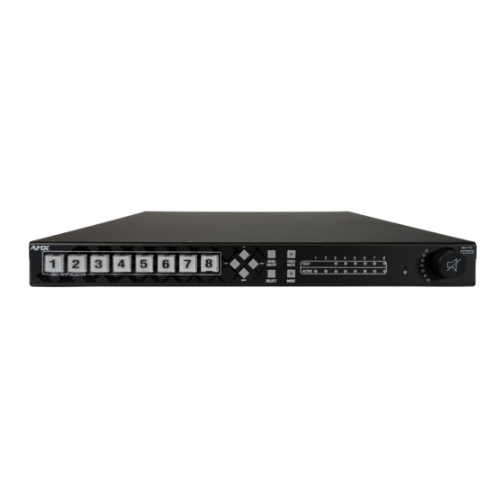
Incite Digital Video Presentation Systems NCITE-813/813A FIG. 2 displays the NCITE-813: FIG. 2 NCITE-813 (front panel) Specifications The following table lists the specifications for the NCITE-813/813A Digital Video Presentation Systems: NCITE-813/813A Specifications General: Enclosure: Metal with black matte finish Dimensions (HWD): 1 11/16”... - Page 17 HDCP Support: • Yes, including HDCP 1.x and HDCP 2.2 • Key Management System • AMX HDCP InstaGate Pro™ Technology • Key support up to 16 devices per output, independent of source device EDID Management: A preferred EDID can be selected for each input or any display EDID can be mirrored to any input independently.
- Page 18 For more details and helpful cabling information, reference the white paper titled Cabling for Success with DXLink, or contact your AMX representative. Microphone Audio: Microphone Input (2) 3.5mm 3-pin captive-wire connectors;...
-
Page 19: Ncite-813Ac
Incite Digital Video Presentation Systems NCITE-813AC FIG. 3 displays the NCITE-813AC: FIG. 3 NCITE-813AC (front panel) Specifications The following table lists the specifications for the NCITE-813AC Digital Video Presentation System: NCITE-813AC Specifications General: Enclosure: Metal with black matte finish Dimensions (HWD): 3 1/2”... - Page 20 Incite Digital Video Presentation Systems NCITE-813AC Specifications (Cont.) Onboard Master: Controller: Integrated Controller is the equivalent of a NetLinx NX-2200 Integrated Controller Memory: •NVRAM: 1 MB •Memory Card: 16 GB SD •DDRAM: 1 GB NOTE: Supports external USB Solid State Drive Processor: 1600 MIPS Program Port:...
- Page 21 HDCP Support: • Yes, including HDCP 1.x and HDCP 2.2 • Key Management System • AMX HDCP InstaGate Pro™ Technology • Key support up to 16 devices per output, independent of source device EDID Management: A preferred EDID can be selected for each input or any display EDID can be mirrored to any input independently.
- Page 22 For more details and helpful cabling information, reference the white paper titled Cabling for Success with DXLink, or contact your AMX representative. Microphone Audio: (2) 3.5mm 3-pin captive-wire connectors; supports up to two mono microphones, unbalanced or bal-...
-
Page 23: Port Numbers
Incite Digital Video Presentation Systems Port Numbers The following table lists the port numbers for the NCITE-813AC: NCITE-813AC Port Numbers RS-232 RS-232/422/485 IR/Serial Relay 11-14 Instruction Manual - Incite Digital Video Presentation Systems... -
Page 24: Installation
Mounting the NCITE-813 into an Equipment Rack The NCITE-813/813A occupies one rack unit (1 RU) in a standard equipment rack. The NCITE-813AC occupies two rack units (2 RU) in a rack. The following steps apply to mounting the presentation systems. -
Page 25: Ventilation
3. Install the presentation system in the mounting rack by using the mounting screws to affix the unit to the rack. Use four screws to mount each bracket on the NCITE-813AC. The NCITE-813/813A requires only two screws for each bracket. -
Page 26: Wiring And Device Connections
OUTPUT (C) FIG. 7 NCITE-813 rear panel The NCITE-813A features the same options on the rear panel as the NCITE-813 with the exception of also featuring 2 AMP OUT captive-wire connectors. FIG. 8 displays the rear panel of the NCITE-813A. -
Page 27: Leds (Ncite-813Ac Only)
NCITE-813AC front panel Front Panel Controls and Indicators The following sub-sections describe each component on the front panel of the NCITE-813 units. Refer to FIG. 6 on page 26 for the component layout of the front panel. LEDs (All NCITE units) This section details the LEDs that appear on the front of all NCITE-813 units. -
Page 28: General Status Leds
Wiring and Device Connections The LEDs on the front panel indicate the communications status of several different connections, as described in the following table: Front Panel LEDs Label Color Description LINK/ACT green Blinks when receiving LAN data packets. STATUS green Blinks to indicate that the system is programmed and communicating properly. -
Page 29: Serial Leds
Wiring and Device Connections The following table lists the following special LED patterns for the Link/Act and Status LEDs: LED Patterns Mode Link/Act Status Normal ON if connected to the Master, blinks off on Blinks as instructed by NetLinx BLINK receiving data message. -
Page 30: Ir/Serial Leds
Wiring and Device Connections IR/SERIAL LEDs The IR/SERIAL LEDs light red to indicate that the corresponding IR/Serial port is transmitting data. There are four IR/SERIAL LEDs on the NCITE-813AC (see FIG. 17). FIG. 17 IR/SERIAL LEDs I/O LEDs The I/O LEDs light yellow to indicate that the corresponding I/O port is active. There are four I/O LEDs on the NCITE-813AC (see FIG. -
Page 31: Navigation Pushbuttons
Wiring and Device Connections Navigation Pushbuttons The four directional navigation buttons (Left/Right/Up/Down) enable you to navigate through and adjust the configurable pa- rameters shown on the On-Screen menu (OSM). The UP and DOWN navigation buttons are used to move between configurable parameters within a menu. -
Page 32: Mode Pushbutton
Wiring and Device Connections MODE Pushbutton Press the MODE pushbutton is reserved for future use. FIG. 24 displays the MODE pushbutton. FIG. 24 MODE Pushbutton Program Port (NCITE-813AC only) The front panel of the NCITE-813AC features one Type-B USB port for connecting the controller to a PC via USB cable. The Pro- gram port uses a standard Type-A-to-Type-B USB cable to connect to a PC. -
Page 33: Video Inputs (1-8)
Wiring and Device Connections Rear Panel Inputs and Outputs The following sub-sections describe each component on the rear panel of the Digital Video Presentation Systems. Refer to FIG. 7 on page 26 for the component layout of the rear panel. VIDEO INPUTS (1-8) The VIDEO INPUTS area on the rear panel consists of eight video ports including 2 VGA ports, 4 HDMI ports, and 2 DXLITE ports. -
Page 34: Hdmi Inputs (3-6)
Wiring and Device Connections HDMI INPUTS (3-6) The HDMI INPUT connectors on the rear panel are used to connect source input devices to the presentation system. The presentation system routes digital video and audio from connected source input devices to the connected output devices. These ports support HDMI (with Deep Color) and HDCP 2.2. - Page 35 Wiring and Device Connections AUDIO INPUTS (1-6) The AUDIO INPUTS connectors are 3.5 mm 5-position captive-wire terminals that can be wired for either balanced (differential) or unbalanced (single-ended) stereo audio. Since the NCITE allows independent switching of video and audio, video and audio inputs of the same number do not have to be connected to the same source equipment.
-
Page 36: Amp Out
Wiring and Device Connections MIC/LINE INPUTS Two 3.5mm 3-pin captive-wire MIC/LINE INPUT connectors allow up to two mono microphones to be connected to the presenta- tion system. Each microphone input supports balanced and unbalanced audio. Each input supports up to 48V of phantom power. FIG. -
Page 37: Audio Outputs
Wiring and Device Connections For mono amplified output, connect a speaker to either the 70V or 100V terminals as displayed in FIG. 37. FIG. 37 Connecting speakers to the Amplified Audio output (-T models) AUDIO OUTPUTS The Line Level audio outputs (ports 1-2) provide balanced or unbalanced, mono or stereo line-level audio output. FIG. -
Page 38: Rear Panel Control And Power (Ncite-813Ac Only)
The following sub-sections describe the control and power components on the rear panel of the NCITE-813AC. These compo- nents are not featured on the NCITE-813 or NCITE-813A. Refer to FIG. 9 on page 27 for the component layout of the rear panel. -
Page 39: Relay Port
Wiring and Device Connections Relay Port The relay port (port 21 on the NCITE-813AC) is an 8-pin 3.5 mm male connector used for connecting external relay devices. You can connect up to 4 independent external relay devices on the NCITE-813AC. When a relay is “OFF”, terminals A and B are open-circuit. -
Page 40: Axlink Port And Led (4-Pin Captive-Wire)
Specifications (per Port) Signal # NCITE-813AC Port # AxLink Port and LED (4-pin captive-wire) The AxLink port allows the central controller to support AMX AxLink devices. FIG. 45 displays the AXLINK port for the NCITE-813AC. FIG. 45 AxLink Ports and LEDs The (green) AxLink LED indicates AxLink data activity: Off - No power, or the controller is not functioning properly. -
Page 41: Configuration Dip Switch
Wiring and Device Connections FIG. 46 provides wiring requirements for the AxLink connector: To the Controller’s AxLink/PWR connector To the external AxLink device Top view Top view FIG. 46 Mini-Phoenix connector wiring diagram (direct data and power) To use the 4-pin 3.5 mm mini-Phoenix (male) captive-wire connector for data communication and power transfer, the incoming PWR and GND cable from the 12 VDC-compliant power supply must be connected to the AxLink cable connector going to the central controller. -
Page 42: Icslan Port
The NCITE-813AC has two types of Ethernet ports: LAN and ICSLAN. The LAN port is used to connect the master to an external network, and the ICSLAN port is used to connect to other AMX equipment or third-party A/V equipment. The ICSLAN port pro- vides Ethernet Communication to connected AMX Ethernet Equipment in a way that is isolated from the primary LAN connection. -
Page 43: Id Pushbutton
LAN 10/100 Port The NCITE-813 features a LAN 10/100 port to provide 10/100 Mbps communication via Category cable. This is an Auto MDI/ MDI-X enabled port, which allows you to use either straight-through or crossover Ethernet cables. The port support IPv4 and IPv6 networks, as well as HTTP, HTTPS, SSH, and FTP. -
Page 44: Ipv4
Wiring and Device Connections The LAN port gets its IP address(es) in one or more of the following ways: IPv4 Static assignment by the user Dynamic assignment by an IPv4 DHCP server Link local as a fall back when configured for DHCP but unable to successfully obtain an address ... -
Page 45: Audio/Video Configuration
Audio/Video Configuration Audio/Video Configuration Overview You can access the configuration settings for the Digital Video Presentation System by using one of the following methods: Using the on-screen menu Using the WebConsole via a Web browser (see page 52) Using the On-Screen Menu You can access the configuration settings for the presentation system by using the MENU ON/OFF button on the front panel of the device. -
Page 46: Audio Settings
Audio/Video Configuration Audio Settings Press the MENU ON/OFF button on the front panel of the presentation system to access the on-screen menu and the Audio settings. The Audio settings appear as default when you access the on-screen menu. The following table lists the audio options available for inputs on the on-screen menu: Audio Settings - Inputs Menu Options INPUTS/OUTPUTS 1-8... -
Page 47: Selecting An Audio Test Tone
Audio/Video Configuration Audio Settings - Outputs Menu Options (Cont.) Test Tone Gener ator Use the left and right navigational buttons to select a test tone for the selected audio output. You can choose from Off, 60Hz, 250Hz, 400Hz, 1kHz, 3kHz, 5kHz, 10kHz, Pink Noise, and White Noise. Audio Group Displays the audio group this to which the amplifier belongs. -
Page 48: Video Settings
Audio/Video Configuration Video Settings Press the MENU ON/OFF button on the front panel of the presentation system to access the on-screen menu and the Video set- tings. When the on-screen menu appears, use the DOWN navigational button to access the Video settings. The following table lists the video options available on the on-screen menu:. - Page 49 Audio/Video Configuration Video Settings Options (Cont.) General Setup Press the right navigational button to access the options for OSD, Video Transition, and Blank/Color Logo. Press the right navigational button to access the options for OSD. Enable OSD Use the left and right navigational buttons to toggle whether you want the On-Screen Display (OSD) overlay to be turned on or off.
-
Page 50: Network Settings
MAC Address Displays the MAC address of the device. System Number Displays the system number for the device. IPV6: (These options only appear on NCITE-813/813A models.) Address 1 The primary IPv6 address of the device. Address 2 The secondary IPv6 address of the device. - Page 51 Audio/Video Configuration WebConsole The Incite presentation systems feature an on-board WebConsole that allows you to configure the device and make various ad- justments to audio/video and system settings. The WebConsole is accessed via a web browser on a PC that has network access to the presentation system.
-
Page 52: Master Controller Configuration Options
NOTE: All NX-Series NetLinx Masters share a common WebConsole, as described in the NetLinx Integrated Controllers WebConsole & Programming Guide (available at www.amx.com). WebConsole - System Configuration The NCITE-813AC (and all other NetLinx Masters) features a built-in WebConsole that allows you to make various configuration settings via a web browser on any PC that has access to the Master. -
Page 53: Default User Names And Passwords
Audio/Video Configuration Locating the IP Address of the Presentation System You can locate the IP address of the presentation system by using the buttons on the front panel of the unit. The IP address ap- pears on the LCD display on the front panel of the device. Perform these steps to locate the IP address of the unit: 1. -
Page 54: On-Board Webconsole User Interface
On the NCITE-813AC, the WebConsole offers three primary sections from a menu located at the top of the page, indicated by three menu options (Network, Security, and Switcher) across the top of the main page (FIG. 64): FIG. 64 System Configuration Menu Options (NCITE-813/813A) Instruction Manual - Incite Digital Video Presentation Systems... -
Page 55: System Configuration Interface Tips
On-Board WebConsole User Interface System Configuration Interface Tips: It is recommended that you use the latest, industry accepted version of HTML5 browsers. If a browser is inconsistent, upgrade or try a different browser. To-date, browsers tested include Google Chrome (preferred), Mozilla Firefox, Apple Safari, and Microsoft Internet Explorer 10+/Edge. -
Page 56: Webconsole - Network Options
NetLinx Setup - Options on this page allow you to establish NetLinx settings for your system. This page is only available on the NCITE-813/813A Presentation Systems. See the Network - NetLinx Setup section on page 62 for details. FIG. 65... -
Page 57: Network - Ipv4 Setup
WebConsole - Network Options Network - IPv4 Setup Click IPv4 Setup to access the IPv4 Setup page (FIG. 66) and view and configure IP and DNS addresses for the Master. Use the options on this page to view/edit the Master’s network settings. A user can only modify the information on this page if it is assigned a Role that includes the Network Configuration permission. -
Page 58: Network - Ipv6 Setup
WebConsole - Network Options Network - IPv6 Setup Click the IPv6 Setup link (on the Network page) to access the IPv6 Setup page (FIG. 67). The options on this page allow you to view the Master’s IPv6 network settings. A user can only modify the information on this page if it is assigned a Role that includes the Network Configuration permission. -
Page 59: Network - Date/Time
WebConsole - Network Options Network - Date/Time Click the Date/Time link (on the Network page) to access the Date/Time page (FIG. 68). The options on this page allow you to enable/disable using a network time source and provide access to Daylight Saving configuration and which NIST servers to use as a reference. -
Page 60: Setting Daylight Savings Rules
WebConsole - Network Options Setting Daylight Savings Rules 1. In the Daylight Savings Time Manager section (FIG. 69), enable Daylight Savings mode by clicking the On button. Clicking On reveals additional Daylight Savings options. FIG. 69 Date/Time Options - Daylight Savings Time Manager 2. -
Page 61: Adding A Custom Nist Server To The List
NOTE: The built-in entries cannot be removed. Refer to Appendix C: Clock Manager NetLinx Programming API in the NetLinx Programming Guide (available at www.amx.com) for a listing and description of the Types/Constants and Library Calls that are included in the NetLinx.AXI to support Clock Manager functions. -
Page 62: Network - Netlinx Setup
Click the NetLinx Setup link (on the Network page) to access the NetLinx Setup page (FIG. 72). The options on this page estab- lish NetLinx settings for your system. This page is only available on the NCITE-813/813A Presentation Systems.. FIG. 72... -
Page 63: Webconsole - Security Options
Additional security configuration options are available via Terminal/Telnet Commands. See Accessing the Security Configuration Options sections in the NetLinx Programming Guide (available at www.amx.com)for more information. NOTE: While the Security page exists on NCITE-813/813A Presentation Systems, the options listed in this chapter are not available for these devices. Login Rules There is no limit to the number of concurrent logins allowed for a single user. -
Page 64: User And Role Name Rules
This user name and password information is also used by both G5 touch panels (within the System Connection firmware page) and AMX software applications such as NetLinx Studio v 4.0 and above to communicate securely with a Master using encrypted communication. -
Page 65: Security - General
WebConsole - Security Options Security - General The General Security Settings page provides global permissions for various options that may be individually selected and applied to all users. The Master provides 3 levels of security settings presets: Low, Medium, and High. The levels are simply presets of various security settings. - Page 66 WebConsole - Security Options System Security Options (Cont.) Option Description Inactivity Timeout Select to enable the Master to log out a user after a defined period of inactivity. After enabling the inactivity timeout op- tion, use the spin box to set the number of minutes before the timeout activates. You can set a timeout in the range of 1 to 60 minutes.
- Page 67 Select to require user name and password authentication on devices connected to the LAN ports on the Master. Devices On LAN Ports LAN AMX Device Select to allow ICSP access to the Master for Device-type users connected to the LAN ports. Expand the LAN AMX Connection Device Connection section to view this option.
-
Page 68: Security Presets
Disabled/Disabled OCSP Disabled Disabled Enabled Switcher Secure Mode Disabled Disabled Enabled Authenticate AMX Devices on Not required Required Required ICSLAN Ports ICSLAN AMX Device Connection ICSPS enabled, ICSP enabled - ICSPS enabled, ICSP enabled - with ICSPS enabled, ICSP disabled... -
Page 69: Banners
WebConsole - Security Options Banners Banners enable you to display pre- and post-login text in the WebConsole and terminal interfaces. Banner files are text files containing up to 5000 characters in each file. (Any additional characters are discarded.) NOTE: Banner files are user-provided and optional. If no files are found, no banner appears. The following special characters are allowed for use in banner text messages: ! ”... -
Page 70: Default Roles
WebConsole - Security Options Default Roles By default, the NetLinx Master creates the following accounts, access rights, directory associations, and security options: Default User Accounts All_Permissions Studio Permissions: All Permissions: • Device Management • Security Control • Firmware/Software Update • General Configuration •... -
Page 71: Adding A New Role
WebConsole - Security Options Role Permissions (Cont.) Security Control Select to allow the role to view and configure security including the following: •HTTP/HTTPS enable • Audit log enable • Inactivity timeout enable • Authentication on server ports enable • ICSP options on ICSLAN •... -
Page 72: Viewing And Modifying Role Security Settings Details
WebConsole - Security Options 4. Enable the security access rights you want to provide to the role. By default, all of these options are disabled. See the Role Permissions section on page 70 for details. 5. Click the Accept button to save your changes to the target Master. If there are no errors within any of the page parameters, a “Role added successfully”... -
Page 73: Locking/Disabling A Role
WebConsole - Security Options Locking/Disabling a Role 1. Select the Roles option (in the Security section) to open the Role Security Details page. 2. Click the Lock button (see FIG. 77) for any Role listed on the Role Security Details page to lock and disable the Role. Click the Lock button again to unlock and enable the Role NOTE: Any Role can be disabled except for the All_Permissions role. -
Page 74: Adding A New User
WebConsole - Security Options Adding a New User TIP: For a quicker configuration, it is recommended to define all roles and permissions before defining users. 1. Select the Users option (in the Security section) to view the User Security Details page. 2. -
Page 75: Viewing And Editing User Security Settings
WebConsole - Security Options Viewing and Editing User Security Settings Click any User listed in the User Security Details page to view the security settings for the selected User (FIG. 80): Edit button click to expand Lock button FIG. 80 Security - Users page 1. -
Page 76: Security Settings - Ldap
Port section in the NetLinx Programming Guide (available at www.amx.com) for details. See Appendix A: LDAP Implementation Details in the NetLinx Programming Guide (available at www.amx.com) for additional infor- mation on implementing LDAP on the NetLinx Master. The LDAP options are described in the following table:... -
Page 77: Accepting Changes
LDAP URI, BIND DN and Search Password settings is displayed. Refer to Appendix A: LDAP Implementation Details in the NetLinx Programming Guide (available at www.amx.com) for additional information. IMPORTANT: For the NX-series Masters to work with LDAP over SSL (LDAPS), you must upload a CA server certificate in .pem format to the Master’s FTP server. -
Page 78: Wired 802.1X Support
WebConsole - Security Options Wired 802.1X support IEEE 802.1X is an IEEE Standard for Port-based Network Access Control (PNAC). PNAC provides the ability to grant or deny net- work access to devices wishing to attach to a LAN based on credentials tied to the device rather than to a user. Until the device has been verified and permitted access, no network traffic is passed through the connected port, effectively keeping the device disconnected from the network. -
Page 79: Security - Profile
WebConsole - Security Options Security - Profile The Profile page (FIG. 82) enables a user to see its own roles and permissions. The user cannot change the roles and permissions on this page. The Change Password option for user accounts is available on this page. FIG. -
Page 80: Webconsole - System Options
See the System - Devices section on page 81 for details. NOTE: This page is not available on the WebConsole for NCITE-813/813A devices. You can find the information listed on the Info tab on the Switcher - Status page for these devices. See the Status Page section on page 100 for more information. -
Page 81: System - Devices
WebConsole - System Options System - Devices The Devices page (FIG. 85) contains information about the Master and any connected devices. Select a device from the Device List and its information appears in the Device Information area. The information in this area is view-only, unless the device allows a change to its device number. -
Page 82: Webconsole - Modules Options
WebConsole - Modules Options WebConsole - Modules Options Modules Overview The Modules page is accessed by clicking Modules on the page’s main heading. This page allows you to view and configure various aspects of the NetLinx System: Device Options - Options on this page display various details specific to additional (non-NetLinx) System Devices. See ... -
Page 83: Modules - Device Options
WebConsole - Modules Options Modules - Device Options Click the Device Options link (in the Manage Devices tab) to access the Details for Additional Devices page (FIG. 86). The options on this page display various details specific to additional (non-NetLinx) System Devices. Configuring Device Binding Options 1. -
Page 84: Modules - Bindings
WebConsole - Modules Options Modules - Bindings Click Bindings to access the Device Bindings page (FIG. 87). Use the options on this page to configure application-de- fined Duet virtual devices with discovered physical devices. FIG. 87 Modules - Bindings The table on this page displays a list of all application-defined devices, including each device’s “Friendly Name”, the Duet virtual device’s D:P:S assignment, the associated Duet Device SDK class (indicating the type of the device), and the physical device’s D:P:S assignment. -
Page 85: Configuring Application-Defined Devices
WebConsole - Modules Options Configuring Application-Defined Devices Elements such as DUET_DEV_TYPE_DISPLAY and DUET_DEV_POLLED are defined within the NetLinx.axi file. The NetLinx.axi file contains both the new API definitions, as well as the pre-defined constants that are used as some of the API arguments (ex: DUET_DEV_TYPE_DISPLAY). -
Page 86: Application Devices And Association Status
WebConsole - Modules Options Application Devices and Association Status There are two types of application devices: Static Bound application devices and Dynamic application devices: Static Bound application devices specify both a Duet virtual device and its associated Device SDK class type, as well as a ... -
Page 87: Modules - User-Defined Devices
WebConsole - Modules Options Modules - User-Defined Devices Click the User-Defined Devices link (in the Manage Devices tab) to access the User-Defined Devices page (FIG. 89). This page provides a listing with all of the dynamic devices that have been discovered in the system, and allows you to add and delete User-Defined Devices. -
Page 88: Modules - Active Devices
WebConsole - Modules Options SDK Class Types Amplifier Digital Video Recorder MultiWindow Text Keypad AudioConferencer Disc Device PoolSpa AudioMixer Display PreAmp Surround Sound Processor AudioProcessor Document Camera Receiver Utility AudioTape HVAC RelayDevice AudioTunerDevice IODevice RFID System Video Conferencer Camera Keypad Security System Video Processor Digital Media Decoder... -
Page 89: Viewing Physical Device Properties
WebConsole - Modules Options Viewing Physical Device Properties Hold the mouse cursor over the Device entry in the table to display detailed device properties for that device, in a pop-up window (FIG. 92). FIG. 92 Active Devices - Device Properties pop-up Instruction Manual - Incite Digital Video Presentation Systems... -
Page 90: Webconsole - Switcher Options
WebConsole - Switcher Options WebConsole - Switcher Options Switcher Overview The Switcher page (FIG. 93) is accessed by clicking Switcher on the page’s main heading. This page allows you to route the sys- tem’s inputs to its outputs during system setup: Configuration - Options on this page allow you to configure audio and video inputs and outputs. -
Page 91: Configuration Page
WebConsole - Switcher Options Configuration Page The Configuration page is used to configure inputs and outputs in the system. The most recently selected input or output displays in the Configuration page. The Configuration page displays the Switching page components on the left. Note that the components are active, i.e., they can be used for all switching functionality. -
Page 92: Configuration Components
WebConsole - Switcher Options Configuration Components The Configuration page features the following components: Inputs section – This section contains buttons for each of the available input signals in the system. Click the input button that needs to be switched. Outputs section – This section contains buttons for each of the available output signals in the system. Note that when the cur- rently selected button is an output, it also appears in the Configuration page with signal details (for button/signal details, click the Legend button). -
Page 93: Video Settings
WebConsole - Switcher Options Video Settings Video settings display when the Switch Mode is A/V or Video, the Video tabbed view is selected, and a specific input or output is selected. Inputs General: Resolution – Displays Resolution (read-only). EDID Mode –... -
Page 94: Audio Settings
WebConsole - Switcher Options Logo Setup: Select Logo File – Click to search and locate a logo file on a local or network drive. Save All Logos – Click to save all logos that you loaded. On-Screen Display: ... -
Page 95: Microphone
WebConsole - Switcher Options Compression: Buttons at top – Click Off, Low, Medium, High, or Custom. Threshold – Use the slider bar to adjust (range: 0 to -60). Attack (ms), Release (ms), and Ratio – Adjust the values in the boxes (either enter values or use the arrows) ... -
Page 96: Outputs
WebConsole - Switcher Options Outputs Port-Specific: Encoding – PCM (read only). Test Tone Enable – Click Disable or Enable. Mute – Click Mute if desired. Changing the volume level will not un-mute the signal; however, the new volume level is ... - Page 97 WebConsole - Switcher Options Mix: Input – Use the slider to adjust the mix level of the audio input for the audio group. Mic1 and Mic2 – Use the sliders to adjust the mix level of the microphone for the audio group. ...
-
Page 98: Selecting An Audio Test Tone
WebConsole - Switcher Options Ducking: Buttons at top – Click Off, Low, Medium, High, or Custom. L/R Mic – Use the slider bar to adjust (range: 0 to -60). Attack (ms), Attenuation (dB), Release (ms) and Hold Time (ms) – Adjust the values in the boxes (either enter values or ... -
Page 99: Changing The Video Output Resolution
WebConsole - Switcher Options Changing the Video Output Resolution Perform these steps to change the video output resolution: 1. Connect to your Presentation System via WebConsole. 2. Pass your pointer device over the Switcher tab so the drop-down menu appears, then select Configuration. The Configuration page opens, and the Video Out tab appears by default (see FIG. -
Page 100: Status Page
Switcher - Status page (NCITE-813AC) NCITE-813/813A devices have a slightly different version of this page with more system information available. The additional information you see on this page is available on the System - Info page on the NCITE-813AC (see the System - Info section on page 80 for more information.) -
Page 101: Windows Page
WebConsole - Switcher Options The following options appear on this page: Switcher - System Page Options Lock Front Panel Click to lock the front panel buttons and prohibit any manual switching or configuration by using the physical buttons on the device. Amp 70v Enable Click to enable the 70V amplifier on the device. -
Page 102: Firmware Upgrades
Alternatively, go to www.amx.com and login as a Dealer to download the latest version. 2. Go to www.amx.com and download the latest Firmware file. Firmware files are available to download from www.amx.com - on the product’s page in the online catalog. -
Page 103: Verifying The Current Firmware Version
Downloading Incite Firmware Files on www.amx.com Visit the appropriate product page on www.amx.com for the latest NX Master and Device Controller firmware (*.kit) files for your Presentation System. Firmware file links are available along the right-side of the catalog page (FIG. 101): FIG. - Page 104 Firmware Upgrades To update NetLinx firmware: 1. Choose Tools > Firmware Transfers > Send to NetLinx Device to open the Send To NetLinx Device dialog box (FIG. 102). Click to locate the KIT file FIG. 102 Send to NetLinx Device dialog box (NetLinx Studio) 2.
-
Page 105: Additional Documentation
Additional Documentation For additional information on using NetLinx Studio, refer to the NetLinx Studio online help and Instruction Manual (available at www.amx.com). Instruction Manual - Incite Digital Video Presentation Systems... -
Page 106: Updating Firmware On Ncite-813/813A
Perform these steps to update the firmware on an NCITE-813/813A Presentation System: 1. Download the latest .kit file from www.amx.com and save the file to a location that is accessible to the Presentation System. 2. Access the WebConsole for the Presentation System (see page 52). -
Page 107: Programming
Programming Programming Overview The chapter defines all programming commands available for the Incite Presentation Systems. NOTE: This chapter lists programming commands unique to Incite Presentation Systems. Please consult the WebConsole & Programming Guide for NX-Series Controllers for more details on NetLinx controller commands. The NCITE-813AC supports all commands compatible with the NX-2200 controller. -
Page 108: Channel Video Switching
Programming NCITE-813AC NetLinx Channels (Cont.) Channel Ports Description Temperature Alarm Power Alarm Audio Group Mute OSD State Channel Video Switching To switch video via channels, the channel must be turned ON (as opposed to pulsing the channel). For example, turn on Channel 31 on Port 1 for Input 1 to output video. -
Page 109: Port Numbers
Programming SEND_COMMANDS The commands listed in the following sections are for the switcher only. For generic NetLinx commands, see the NetLinx Inte- grated Controllers WebConsole and Programming Guide. The commands derive their input/output port addressing from the target D:P:S. INPUT ports range from 1-14 for Audio and from 1-8 for Video. -
Page 110: Audio Send_Commands
Programming AUDIO SEND_COMMANDs The following table lists the audio SEND_COMMANDs available for the NCITE-813AC:Video SEND_COMMANDs Audio SEND_COMMANDs Switches audio input port <input> to audio output port <output>. AI<input>O<output> Syntax: SEND_COMMAND “’AI<input>O<output>’” Variables: input = The source audio input number. output = The audio output port number to switch to. Example: SEND_COMMAND SWITCHER,”’AI2O1’”... -
Page 111: Audin_Compression_Release
Programming Audio SEND_COMMANDs (Cont.) ?AUDIN_COMPRESSION_ Requests the compression release for the audio port. RELEASE Syntax: SEND_COMMAND <DEV>, “’?AUDIN_COMPRESSION_RELEASE’” Example: SEND_COMMAND AUDIO_1, “’?AUDIN_COMPRESSION_RELEASE’” Returns a COMMAND string of the form: AUDIN_COMPRESSION_RELEASE-<release> AUDIN_COMPRESSION_RE- Sets the duration of the release phase while compressing for the audio port addressed by the D:P:S. LEASE Syntax: SEND_COMMAND <DEV>, “’AUDIN_COMPRESSION_RELEASE-<release>’”... -
Page 112: Audin_Stereo
Programming Audio SEND_COMMANDs (Cont.) ?AUDIN_STEREO Requests to see if the audio port addressed by the D:P:S has the stereo setting enabled or disabled. Syntax: SEND_COMMAND <DEV>, “’?AUDIN_STEREO’” Example: SEND_COMMAND AUDIO_INPUT_1,”’?AUDIN_STEREO’” Returns a COMMAND string of the form: AUDIN_STEREO-<setting> AUDIN_STEREO Enables or disables the stereo setting on the audio port addressed by the D:P:S. If enabled, the stereo setting is on. -
Page 113: Audmic_Compression_Release
Programming Audio SEND_COMMANDs (Cont.) ?AUDMIC_COMPRESSION_ Requests the duration of the release phase while compressing for a microphone. RELEASE Syntax: SEND_COMMAND <DEV>, “’?AUDMIC_COMPRESSION_RELEASE’” Example: SEND_COMMAND MIC_1, “’?AUDMIC_COMPRESSION_RELEASE’” Returns a COMMAND string of the form: AUDMIC_COMPRESSION-RELEASE-<release> AUDMIC_COMPRESSION_ Sets the duration of the release phase while compressing for the microphone port addressed by the D:P:S. -
Page 114: Audmic_Duck_Release
Programming Audio SEND_COMMANDs (Cont.) AUDMIC_DUCK_RELEASE Sets the duration of the release phase while ducking from the microphone port addressed by the D:P:S. Syntax: SEND_COMMAND <DEV>, “’AUDMIC_DUCK_RELEASE-<release>’” Variable: release = 10 to 5000 Example: SEND_COMMAND MICROPHONE_1, “’AUDMIC_DUCK_RELEASE-200’” Sets the ducking release for the microphone port (#1 based on the D:P:S) to 200. Requests the frequency for the specified microphone band of the equalizer for the microphone port ?AUDMIC_EQ_CF addressed by the D:P:S. -
Page 115: Audmic_Eq_Gain
Programming Audio SEND_COMMANDs (Cont.) AUDMIC_EQ_GAIN Sets the gain on the microphone equalizer band <band> on the output audio port addressed by the D:P:S to <value>. Syntax: SEND_COMMAND <DEV>, “’AUDMIC_EQ_GAIN-<band>,<value>’” Variables: band = 1..3 on the microphone inputs. value = -12..12. The units are in dB. Example: SEND_COMMAND MIC_1,”’AUDMIC_EQ_GAIN-1,8’”... -
Page 116: Audmic_Gating
Programming Audio SEND_COMMANDs (Cont.) ?AUDMIC_GATING Requests the setting of gating of a microphone. Syntax: SEND_COMMAND <DEV>, “’?AUDMIC_GATING’” Example: SEND_COMMAND MICROPHONE_1, “’?AUDMIC_GATING’” Returns a COMMAND string of the form: AUDMIC_GATING-<setting> AUDMIC_GATING Sets the setting of gating of the microphone port addressed by the D:P:S to <option>. Syntax: SEND_COMMAND <DEV>, “’AUDMIC_GATING-<setting>’”... -
Page 117: Audmic_Gating_Release
Programming Audio SEND_COMMANDs (Cont.) ?AUDMIC_GATING_RELEAS Requests the duration of the release phase while gating from the microphone port addressed by the D:P:S. Syntax: SEND_COMMAND <DEV>, “’?AUDMIC_GATING_RELEASE’” Example: SEND_COMMAND MIC_1, “’?AUDMIC_GATING_RELEASE’” Returns a string of the form: AUDMIC_GATING_RELEASE=<value> AUDMIC_GATING_RELEASE Sets the duration of the release phase while gating from the microphone port addressed by the D:P:S. -
Page 118: Audmic_Limiter_Release
Programming Audio SEND_COMMANDs (Cont.) ?AUDMIC_LIMITER_RELEASE Requests the duration of the release phase while limiting from the microphone port addressed by the D:P:S. Syntax: SEND_COMMAND <DEV>, “’?AUDMIC_LIMITER_RELEASE’” Example: SEND_COMMAND MIC_1, “’?AUDMIC_LIMITER_RELEASE’” Returns a string of the form: AUDMIC_LIMITER_ RELEASE=<release> AUDMIC_LIMITER_RELEASE Sets the duration of the release phase while limiting for the microphone port addressed by the D:P:S. -
Page 119: Audmic_Preamp_Gain
Programming Audio SEND_COMMANDs (Cont.) ?AUDMIC_PREAMP_GAIN Requests the gain of the microphone before the amplifier. Syntax: SEND_COMMAND <DEV>, “’?AUDMIC_PREAMP_GAIN’” Example: SEND_COMMAND MIC_1,”’?AUDMIC_PREAMP_GAIN’” Returns a COMMAND string of the form: AUDMIC_PREAMP_GAIN-<gain> AUDMIC_PREAMP_GAIN Sets the pre-amplifier gain of the microphone addressed by the D:P:S to <value>. Syntax: SEND_COMMAND <DEV>, “’AUDMIC_PREAMP_GAIN-<gain>’”... -
Page 120: Audout_Duck_Attack
Programming Audio SEND_COMMANDs (Cont.) AUDOUT_DUCK_ATTACK Sets the duration of the attack phase while ducking for the output port addressed by the D:P:S. Syntax: SEND_COMMAND <DEV>, “’AUDOUT_DUCK_ATTACK-<attack>’” Variable: attack = 1 to 2000 Example: SEND_COMMAND AUDIO_OUTPUT_1, “’AUDOUT_DUCK_ATTACK-200’” Sets the ducking attack for the output port (#1 based on the D:P:S) to 200. Sets the duration of the hold phase while ducking for the output port addressed by the D:P:S. -
Page 121: Audout_Ducking
Programming Audio SEND_COMMANDs (Cont.) AUDOUT_DUCKING Sets the setting of ducking for the audio port addressed by the D:P:S. Syntax: SEND_COMMAND <DEV>, “’AUDOUT_DUCKING-<setting>’” Variable: setting = off, low, medium, high, custom Example: SEND_COMMAND AUDIO_OUTPUT_1, “’AUDOUT_DUCKING-low’” Sets the ducking for the audio output port (#1 based on D:P:S) to low. ?AUDOUT_EQ_CF Requests the center frequency on the equalizer setting of band <band>... -
Page 122: Audout_Eq_Gain
Programming Audio SEND_COMMANDs (Cont.) AUDOUT_EQ_GAIN Sets the gain on the equalizer band <band> on the output audio port addressed by the D:P:S to <value>. Syntax: SEND_COMMAND <DEV>, “’AUDOUT_EQ_GAIN-<band>,<value>’” Variables: band = 1..10 if on the audio output port. value = -12..12. The units are in dB. Example: SEND_COMMAND AUDIO_OUTPUT_1,”’AUDOUT_EQ_GAIN-1=8’”... -
Page 123: Audout_Maxvol
Programming Audio SEND_COMMANDs (Cont.) AUDOUT_MAXVOL Sets the maximum volume for the audio port addressed by the D:P:S. Syntax: SEND_COMMAND <DEV>, “’AUDOUT_MAXVOL-<maximum>’” Variable: maximum = -100 to 0 in percent Example: SEND_COMMAND AUDIO_OUTPUT_1, “’AUDOUT_MAXVOL--75’” Sets the maximum for the audio output port (#1 based on D:P:S) to 75%. Requests the current minimum volume for the audio port addressed by the D:P:S. - Page 124 Programming Audio SEND_COMMANDs (Cont.) Requests the current frequency of test tone for the audio port addressed by the D:P:S. ?AUDOUT_TESTTONE Syntax: SEND_COMMAND <DEV>, “’?AUDOUT_TESTTONE’” Example: SEND_COMMAND AUDIO_OUTPUT_1, “’?AUDOUT_TESTTONE’” Returns a COMMAND string of the form: AUDOUT_TESTTONE-<frequency>. AUDOUT_TESTTONE Sets the frequency, if any, of a test tone for the audio port addressed by the D:P:S. Syntax: SEND_COMMAND <DEV>, “’AUDOUT_TESTTONE-<frequency>’”...
- Page 125 Programming Audio SEND_COMMANDs (Cont.) XPOINT Sets the mix level that the audio input addressed by the parameter <input> provides to the audio output <output> to <value>. Note: Audio input ports 1..10 share a setting across them for a specific output mixer’s value. Syntax: SEND_COMMAND <DEV>, “’XPOINT-<value>,<input>,<output>’”...
- Page 126 Programming Video SEND_COMMANDs (Cont.) VIDIN_EDID_AUTO Sets whether you want the EDID source for the video input to update the list of available resolutions at regular intervals. Syntax: SEND_COMMAND <DEV>,”’VIDIN_EDID_AUTO-<ENABLE|DISABLE>’” Example: SEND_COMMAND VIDEO_INPUT_1,”’VIDIN_EDID_AUTO-ENABLE’” ?VIDIN_FORMAT Requests the input format of the video port addressed by the D:P:S. Syntax: SEND_COMMAND <DEV>, “’?VIDIN_FORMAT’”...
- Page 127 Programming Video SEND_COMMANDs (Cont.) VIDIN_NAME Sets the input name of the video port addressed by the D:P:S to <name>. The <name> length is limited to 63 characters (31 characters for ICSP). Specifying a longer name will result in truncation to the character length limit. Valid characters are: a-z // lower case letters A-Z // upper case letters...
- Page 128 Programming Video SEND_COMMANDs (Cont.) VIDIN_RES_REF Sets the resolution and refresh rate of the video input port addressed by D:P:S. Invalid combina- tions are ignored by the SWITCHER. Syntax: SEND_COMMAND <DEV>,”’VIDIN_RES_REF-<horizontal>x<vertical>,<refresh-rate>’” Variables: horizontal = An integer value representing the horizontal. vertical = An integer value representing the vertical. May have an additional qualifier such as ‘i’ or ‘p’. refresh-rate = An integer value representing the refresh rate.
- Page 129 Programming Video SEND_COMMANDs (Cont.) VIDOUT_BLANK Sets the image of the video blanking feature for the video output port addressed by the D:P:S. Syntax: SEND_COMMAND <DEV>,”’VIDOUT_BLANK-<color>’” Variables: image = black, blue, logo 1, logo 2, logo 3 Example: SEND_COMMAND VIDEO_OUTPUT_1,”’VIDOUT_BLANK-logo 1’” ?VIDOUT_BRIGHTNESS Requests the output brightness of the video port addressed by the D:P:S.
- Page 130 Programming Video SEND_COMMANDs (Cont.) ?VIDOUT_OSD Requests whether the video output ports have the OSD setting enabled or disabled. Syntax: SEND_COMMAND <DEV>, “’?VIDOUT_OSD’” Example: SEND_COMMAND VIDEO_OUTPUT_1,”’? VIDOUT_OSD’” Returns a COMMAND string of the form: VIDOUT_OSD-<ENABLE|DISABLE> VIDOUT_OSD Enables or Disables the On Screen Display (OSD) setting on the video output ports. If enabled, then the OSD setting is on.
-
Page 131: Vidout_Testpat
Programming Video SEND_COMMANDs (Cont.) VIDOUT_RES_REF Sets the resolution and refresh rate of the video output ports. Invalid combinations are ignored by the All-In-One Presentation Switcher. Syntax: SEND_COMMAND <DEV>,”’VIDOUT_RES_REF-<horizontal>x<vertical>,<refresh-rate>’” Variables: horizontal = An integer value representing the horizontal.vertical = An integer value repre- senting the vertical. -
Page 132: Fp_Lockout
Programming Front Panel SEND_COMMANDs The following table lists the front panel SEND_COMMANDs available for the NCITE-813AC: Front Panel SEND_COMMANDs Requests to see if the Front Panel is locked out. ?FP_LOCKOUT Syntax: SEND_COMMAND <DEV>, “’?FP_LOCKOUT’” Example: SEND_COMMAND SWITCHER,”’?FP_LOCKOUT’” Returns a COMMAND string of the form: FP_LOCKOUT-<ENABLE|DISABLE>... -
Page 133: Window Positioning Send_Commands
Programming Window Positioning SEND_COMMANDs The following table lists the Window Positioning SEND_COMMANDs available for the NCITE-813AC: Window Positioning SEND_COMMANDs Requests the position of the secondary window when PIP is selected as the View Mode. ?PIP_POS Syntax: SEND_COMMAND <DEV>, “’?PIP_POS’” Example: SEND_COMMAND SWITCHER,”’PIP_POS-BOTTOM RIGHT’”... -
Page 134: View_Mode
Programming Window Positioning SEND_COMMANDs ?VIEW_MODE Requests the viewing mode for the video output. Syntax: SEND_COMMAND <DEV>, “’?VIEW_MODE’” Example: SEND_COMMAND SWITCHER,”’VIEW_MODE’” Returns a COMMAND string of the form: VIEW_MODE-<mode>. VIEW_MODE This command sets the viewing mode for the video output. The default mode is Transition. Syntax: SEND_COMMAND <DEV>, “’VIEW_MODE-<mode>’”... -
Page 135: Appendix A - Input Resolutions
Appendix A - Input Resolutions Appendix A - Input Resolutions Available Pixel Display and Refresh Rates The available pixel display and refresh rates for the input devices on the Digital Video Presentation Systems are listed in the following sections. DVI, HDMI, and VGA Supported Input Resolutions DVI, HDMI, and VGA Supported Input Resolutions Resolution Name Horizontal... - Page 136 Appendix A - Input Resolutions DVI, HDMI, and VGA Supported Input Resolutions (Cont.) Resolution Name Horizontal Vertical Refresh HDMI & Comments Video Active Pixels Active (Hz) Support Standard Lines Support 1280x800@60 1280 VESA CVT 1280x960@60 1280 VESA DMT ...
-
Page 137: Appendix B - Output Resolutions
Appendix B - Output Resolutions Appendix B - Output Resolutions Available Pixel Display and Refresh Rates The available pixel display and refresh rates for the output devices on the Digital Video Presentation System are listed in the following section. DVI and HDMI Supported Output Resolutions DVI and HDMI Supported Output Resolutions Resolution Name Horizontal Active Vertical Active... -
Page 138: Appendix C - Volume Attenuation Table
Appendix C - Volume Attenuation Table Appendix C - Volume Attenuation Table Overview Volume attenuation on the Incite Presentation Systems is not set by percentage. On the Incite Presentation Systems, the output volume slider changes .5dB per click to provide a more subtle adjustment. Unity gain is at 88, so a setting of 100 is actually 6dB gain. - Page 139 Appendix C - Volume Attenuation Table Volume Attenuation (Cont.) Percent Decibels Percent Decibels -13.5 -39.0 -14.0 -41.0 -14.5 -46.0 -15.0 -51.0 -15.5 -56.0 -16.0 -61.0 -16.5 -66.0 -17.0 -71.0 -17.5 -76.0 -18.0 -81.0 -18.5 Infinity -19.0 Instruction Manual - Incite Digital Video Presentation Systems...
- Page 140 © 2018 Harman. All rights reserved. Enova, NetLinx, AMX, AV FOR AN IT WORLD, HARMAN, and their respective logos are registered trademarks of LAST REVISED: HARMAN. Oracle, Java and any other company or brand name referenced may be trademarks/registered trademarks of their respective companies.
Need help?
Do you have a question about the NCITE-813 and is the answer not in the manual?
Questions and answers