
Related Manuals for AMX NMX-PRS-N7142


Summary of Contents for AMX NMX-PRS-N7142
- Page 1 IN ST RU CT ION MAN UAL N 7 1 4 2 P R E S E N TAT I O N SW I TC H E R W I T H N E T WO R K E D AV NMX- PR S- N7 142, N MX -P RS-N 71 42-23...
-
Page 2: Important Safety Instructions
COPYRIGHT NOTICE AMX© 2018, all rights reserved. No part of this publication may be reproduced, stored in a retrieval system, or transmitted, in any form or by any means, electronic, mechanical, photocopying, recording, or otherwise, without the prior written permission of AMX. Copyright protection claimed... -
Page 3: Esd Warning
Anyone performing field maintenance on AMX equipment should use an appropriate ESD field service kit complete with at least a dissipative work mat with a ground cord and a UL listed adjustable wrist strap with another ground cord WARNING: Do Not Open! Risk of Electrical Shock. -
Page 4: Table Of Contents
Table of Contents Chapter 1: Introducing Your New N7142 Room Switcher ........... 6 Product Overview..............................6 Common Applications............................. 6 Features include: ............................6 Hardware Overview..............................7 Chapter 2: Installing the N7142 ................... 9 Physical Installation .............................. 9 Initial Setup................................9 Internal Switch Configuration ........................ - Page 5 Users Page ................................47 Panel Builder Page.............................. 48 Chapter 5: Troubleshooting ....................49 Appendix A: Panel Builder ....................50 Beginning a Panel Builder Project........................50 Top Ribbon Option Descriptions ......................... 52 Project Pane Option Descriptions ........................53 Item Properties Tab............................53 Panel Tab..............................
-
Page 6: Chapter 1: Introducing Your New N7142 Room Switcher
There are two models of the N7142. The NMX-PRS-N7142 is the base presentation switcher, with two available Networked AV slots that can be populated with Encoder and Decoder cards as required by the application. The NMX-PRS-N7142-23 is an identical presentation switcher, pre-populated with one N2312 Encoder card and one N2322 Decoder card, making it perfect for cost- sensitive 4K video distribution applications. -
Page 7: Hardware Overview
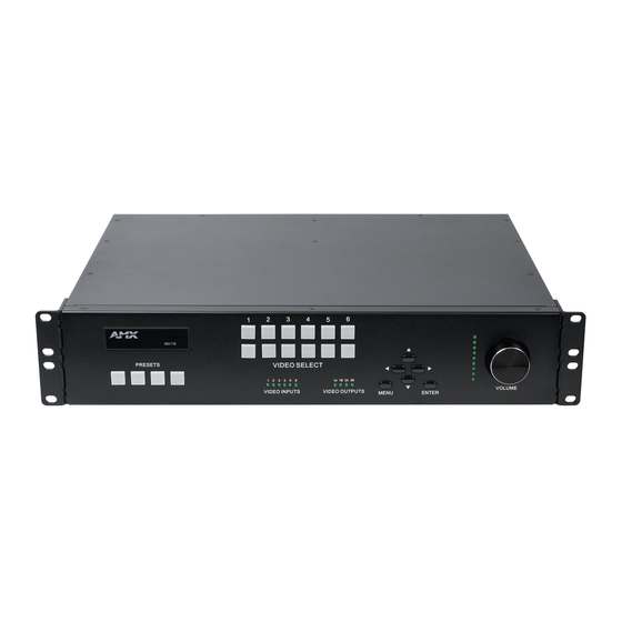
Introducing Your New N7142 Room Switcher Hardware Overview Refer to the following figures (front and rear panel drawings) and the corresponding tables (on page 7 page 8) for hardware details. 1) Presets Buttons 5) Menu Button 2) Video Select Buttons 6) Arrow Buttons 3) Video Inputs LEDs 7) Enter Button... - Page 8 12 Volt DC power output. Can be used to power the Networked AV Cards (if PoE is not being used). Networked AV Card Slots Dependent on model type. NMX-PRS-N7142: Slots can be populated with Encoder and Decoder cards as required by the application. NMX-PRS-N7142-23: Slots are pre-populated with one N2312 Encoder card and one N2322 Decoder card. AUDIO INPUTS/OUTPUTS Extensive audio selections are supported including a built-in DSP and 60W stereo amplifier capable of operating in 4Ω/8Ω, 70V, or 100V modes.
-
Page 9: Chapter 2: Installing The N7142
Follow the steps below for initial software setup of the N7142. Once the unit completes the boot up process and the attached monitor displays the AMX logo, press the MENU button (on the N7142’s front panel) to access the On-Screen Display (OSD) setup menu. The Quick Setup page displays (see... -
Page 10: Internal Switch Configuration
Installing the N7142 Internal Switch Configuration Once the switch’s IP address has been configured, you can access all switch settings via your web browser. Enter the switch’s IP address into your browser window. When the login screen appears, enter admin as the username. Upon successful login, the Port State Overview page will display (shown in Figure NOTE: No password is required initially, but you should create one immediately for security purposes (select Configuration >... - Page 11 Installing the N7142 FIG. 7 CIST Port Configuration Page Select Configuration > Security > AAA > Radius (as shown in Figure Click Add New Server and enter the server Hostname/Secret Key/etc. Click Save. FIG. 8 Radius Server Configuration Page N7142 User Manual...
- Page 12 Installing the N7142 Select Configuration > Security > Network > NAS (as shown in Figure Under System Configuration, change the Mode to Enabled. Under Port Configuration, change the Admin State of the desired port to any of the 802.1x options (Port-based, Single, Multi, etc.).
-
Page 13: Advanced Configuration
Installing the N7142 Advanced Configuration For more advanced N7142 Switcher configuration options, enter the unit’s IP address into your web browser. When prompted, enter the default username and password (admin and password). The Switcher Configuration page displays (see Figure 10). From here, you can view the status of the N7142’s Inputs and Outputs as well as make minor configuration adjustments. -
Page 14: Chapter 3: Room Switcher Configuration Options
This chapter defines the N7142 Room Switcher configuration options accessible via the On-Screen Display (OSD) setup menu. Once the unit completes the boot up process and the attached monitor displays the AMX logo, press the MENU button (on the front panel of the unit) to access this interface. -
Page 15: Quick Setup Page
Room Switcher Configuration Options Quick Setup Page Click the Quick Setup link in the left menu bar to access the page shown in Figure 12. See Table 4 for option descriptions. Quick Setup Page FIG. 12 Quick Setup Page Options TABLE 4 Option Description... -
Page 16: User Presets Page
Room Switcher Configuration Options User Presets Page Click the User Presets link in the left menu bar to access the page shown in Figure 13. See Table 5 for option descriptions. User Presets Page FIG. 13 User Presets Page Options TABLE 5 Option Description... -
Page 17: Input Page
Room Switcher Configuration Options Input Page Click the Input link in the left menu bar to access the page shown in Figure 14. Current AV input status information is displayed here. Input Page FIG. 14 N7142 User Manual... -
Page 18: Output Page
Room Switcher Configuration Options Output Page Click the Output link in the left menu bar to access the page shown in Figure 15. See Table 6 for option descriptions. Output Page FIG. 15 Output Page Options TABLE 6 Option Description HDMI Output 1/2 Select the output Resolution and Colorspace settings of the video to be transmitted to the video output device (e.g., an LCD screen). -
Page 19: Networking Page
Room Switcher Configuration Options Networking Page Click the Networking link in the left menu bar to access the page shown in Figure 16. See Table 7 for option descriptions. Networking Page FIG. 16 Networking Page Options TABLE 7 Option Description N7142 Network: These settings apply to the N7142 Room Switcher. -
Page 20: Audio Page
Room Switcher Configuration Options Audio Page Click the Audio link in the left menu bar to access the page shown in Figure 17. See Table 8 for option descriptions. Audio Page FIG. 17 Audio Page Options TABLE 8 Option Description Analog 1-6 Choose to mute/unmute the selected audio. -
Page 21: Advanced Page
Room Switcher Configuration Options Advanced Page Click the Advanced link in the left menu bar to access the page shown in Figure 18. See Table 9 for option descriptions. Advanced Page FIG. 18 Advanced Page Options TABLE 9 Option Description Factory Restore Click to restore the device to the original factory settings. -
Page 22: Device Info Page
Room Switcher Configuration Options Device Info Page Click the Device Info link in the left menu bar to access the page shown in Figure 19. Here you can view release and product version information as well as the current internal temperature of the N7142 (in degrees Celsius). Device Info Page FIG. -
Page 23: Chapter 4: Room Switcher Detailed Configuration Options
Room Switcher Detailed Configuration Options Chapter 4: Room Switcher Detailed Configuration Options This chapter defines N7142 Room Switcher configuration options. Access these options by entering the unit’s IP address into your browser. The default username/password is admin and password). For ease of navigation, this chapter is organized to reflect the webpage’s graphical user interface (GUI). From any main page in the GUI, you can access all other main pages by clicking the links in the top navigation bar. -
Page 24: Settings Page
Room Switcher Detailed Configuration Options Settings Page Click the Settings link at the top of any of the main web pages to access the page shown in Figure 21. This page is divided into several sections and also has links to other dialog boxes for additional configuration options. Refer to the following sections for detailed descriptions: Room Switcher Setup Section on page 25 ... -
Page 25: Room Switcher Setup Section
Room Switcher Detailed Configuration Options Room Switcher Setup Section The Room Switcher Setup section of the Settings page is shown in Figure 22. Options are described in Table Room Switcher Setup Section FIG. 22 Settings Page: Room Switcher Setup Section TABLE 10 Option Description... - Page 26 Room Switcher Detailed Configuration Options Settings Page: Room Switcher Setup Section (Cont.) TABLE 10 Option Description Notes Output 1 and 2 Video Enable to mute the video. If enabled, the video output displays black instead of Mute live video. Cancel Click to return all controls to the last saved This button affects all Room Switcher Setup controls configuration.
-
Page 27: Network Setup Section
Room Switcher Detailed Configuration Options Network Setup Section The Network Setup section of the Settings page is shown in Figure 23. Options are described in Table Network Setup Section FIG. 23 Settings Page: Network Setup Settings TABLE 11 Option Description Notes IP Mode Configure the IP address mode. -
Page 28: Status Section
Room Switcher Detailed Configuration Options Settings Page: Network Setup Settings (Cont.) TABLE 11 Option Description Notes Switch Network Configure network switch settings for the N7142’s Once the switch’s IP address has been configured, you built-in, six-port switch. can access all switch settings via your web browser. Enter the Switch Network IP address into your browser window. -
Page 29: Change Password Section
Room Switcher Detailed Configuration Options Settings Page: Status Section (Cont.) TABLE 12 Option Description Notes Serial Source IP Shows the IP address of the currently connected device Only a single external connection can be accepted on or displays Disconnected if no connection exists. the port. -
Page 30: Software Section
Room Switcher Detailed Configuration Options Software Section The Software section of the Settings page is shown in Figure 27. Options are described in Table Software Section FIG. 27 Settings Page: Software Section TABLE 14 Option Description Serial Displays the serial number of the N2400 Room Switcher. MAC Address Displays the MAC address of the network interface of the N2400 Room Switcher. - Page 31 Room Switcher Detailed Configuration Options Front Panel Page Options TABLE 15 Option Description VIDEO SELECT buttons Click to switch video to a different output. Use the VIDEO SELECT buttons to choose which video input (1-6) is displayed. The top row of buttons sends the video to VIDEO OUTPUT 1.
-
Page 32: Switcher Page
Room Switcher Detailed Configuration Options Switcher Page Click the Switcher link at the top of the webpage to access the page shown in Figure 29. This is also the first page that displays when you log in to the unit’s webpage. From here, you can view the status of the N7142’s Inputs and Outputs as well as make minor configuration adjustments. - Page 33 Room Switcher Detailed Configuration Options Audio/Video Status Legend FIG. 30 N7142 User Manual...
-
Page 34: Audio Page
Room Switcher Detailed Configuration Options Audio Page Click the Audio link at the top of any of the main web pages to access the page shown in Figure 31. See Table 17 for option descriptions. This page is divided into several sections and also has links to other dialog boxes for additional configuration options. Refer to the following sections for detailed descriptions: Inputs Tab on page 34 ... -
Page 35: Mixing Tab
Room Switcher Detailed Configuration Options Mixing Tab The Mixing Tab section of the Audio page is shown in Figure 32. Options are described in Table Use this page to configure mixes for the following outputs: ineout audio outputs. These outputs are located on the rear of the The Line Out 1 and Line Out 2 columns correspond to the l ... -
Page 36: Eq & Outputs Tab
Room Switcher Detailed Configuration Options EQ & Outputs Tab The EQ & Outputs Tab section of the Audio page is shown in Figure 33. Options are described in Table Use this page to configure settings for the following outputs: ineout audio outputs. These outputs are located on the rear of the The Line Out 1 and Line Out 2 sections correspond to the l ... - Page 37 Room Switcher Detailed Configuration Options Audio Page: EQ & Outputs Tab (Cont.) TABLE 19 Option Description Sets the mixer output left balance control on the specified output Left Channel (%) Sets the mixer output right balance control on the specified output Right Channel (%) Amp Out Settings Mute...
-
Page 38: Advanced Tab
Room Switcher Detailed Configuration Options Advanced Tab The Advanced Tab section of the Audio page is shown in Figure 34. Options are described in Table Audio Page: Advanced Tab FIG. 34 Audio Page: Advanced Tab TABLE 20 Option Description Save Settings button Saves current configuration. - Page 39 Room Switcher Detailed Configuration Options Audio Page: Advanced Tab (Cont.) TABLE 20 Option Description Feedback Cancel Gain Inc Step Determines how quickly the gain returns to its normal state (no attenuation). Feedback Cancel Gain Dec Step Determines how quickly the attenuation is applied. Noise Reduction Enables noise reduction.
- Page 40 Room Switcher Detailed Configuration Options Audio Page: Advanced Tab (Cont.) TABLE 20 Option Description Compressor Attack Time (sec) Sets the compressor attack time in seconds on the specified output. The attack time determines how fast the compressor processor detects oscillations. Compressor Release Time (sec) Sets the compressor release time in seconds on the specified output.
-
Page 41: Ir Page
Room Switcher Detailed Configuration Options IR Page Click the IR link at the top of any of the main web pages to access the page shown in Figure 35. This page allows you to upload and execute IR Pronto codes so that other vendor’s devices can be controlled through the Room Switcher’s IR connector. Commands can be saved for future use and executed later. -
Page 42: N-Act Page
Room Switcher Detailed Configuration Options N-Act Page Click the N-Act link at the top of any of the main web pages to access the page shown in Figure 36. This page allows you to create command lists which are performed automatically by the unit based on power or video connection (without the use of an outside controller). -
Page 43: Serial Page
Room Switcher Detailed Configuration Options Serial Page Click the Serial link at the top of any of the main web pages to access the page shown in Figure 37. This page allows you to upload and execute commands used for direct control of serial devices. Commands may be saved for future use and executed later. The Serial Code menu lists all saved commands. -
Page 44: Security Page
Room Switcher Detailed Configuration Options Security Page Click the Security link at the top of any of the main web pages to access the page shown in Figure 38. This page allows you to customize the security settings on your unit. See Table 24 for option descriptions. -
Page 45: Logs Page
You can then download and send it to AMX tech support. Logs Page FIG. 39 NOTE: For security reasons, only use the Enable Maintenance Mode if instructed by AMX Technical Support. This selection only appears in the secure version of the website (i.e., https). NetLinx Page... - Page 46 Room Switcher Detailed Configuration Options NetLinx Page Options TABLE 25 Command Description Enable Click to enable/disable NetLinx on this device. Device Status This status field will show the device to be Online, Connected, Offline, or Unknown. Master Mode Select Auto, Listen, or URL. IP/URL Enter the address of the Master Controller.
-
Page 47: Users Page
Room Switcher Detailed Configuration Options Users Page Click the Users link at the top of any of the main web pages to access the page shown in Figure 41. Options are described in Table 26. This page allows you to assign specific privileges to different users. Users Page FIG. -
Page 48: Panel Builder Page
Room Switcher Detailed Configuration Options Panel Builder Page Click the Panel Builder link at the top of any of the main web pages to access the initial page shown in Figure 42. Panel Builder is a GUI application that allows you to create custom panels to be used as a standalone control option or as an extension to a third- party control system. -
Page 49: Chapter 5: Troubleshooting
Troubleshooting Chapter 5: Troubleshooting This chapter contains possible solutions to some common issues. Should you encounter any problems not covered by these guidelines, please contact SVSI technical support via email (svsisupport@harman.com) or call 256.461.7143 x9900. Issues Suggestions No video displayed on monitor. •... -
Page 50: Appendix A: Panel Builder
Appendix A: Panel Builder Appendix A: Panel Builder Panel Builder allows you to design attractive, intuitive, and easy-to-use touch panel layouts for controlling SVSI’s Networked AV Systems and third-party equipment. Panel Builder provides an easy way to design a panel to control any room or facility with just a few simple steps. - Page 51 Appendix A: Panel Builder Project Editor FIG. 45 NOTE: For step-by-step panel building instructions, refer to the Panel Builder Tutorial (available in the Panel Builder Help menu). Once you arrive at the main Project Editor page, the following screen is displayed. See the sections referenced in the callouts for descriptions of each area of the Project Editor interface.
-
Page 52: Top Ribbon Option Descriptions
Appendix A: Panel Builder Top Ribbon Option Descriptions Refer to Table 27 for detailed descriptions of the options available in the top ribbon of the Project Editor initial page. Hold the Shift key when selecting multiple buttons/widgets (for aligning groups of objects, etc.). Top Ribbon Option Descriptions TABLE 27 Option... -
Page 53: Project Pane Option Descriptions
Appendix A: Panel Builder Top Ribbon Option Descriptions (Cont.) TABLE 27 Option Description Delete a panel from the current project. Add a panel to the current project. Scroll through the panels of the current project. Project Pane Option Descriptions On the right side of the main screen, you will find options that allow you to edit the current panel you are building, your overall project, as well as view your project assets (such as available images, created scripts, and related modules). -
Page 54: Panel Tab
Appendix A: Panel Builder Item Properties Pane Option Descriptions (Cont.) TABLE 28 Option Description Border Set the border width/color/etc. for the selected item. Box, Drop, and Text Add/remove/adjust shadow settings for the selected item. Shadow Touch Panel Key Use to assign a touch panel key number (if applicable). Icon Choose an image to serve as an icon for the selected item. -
Page 55: Project Tab
Appendix A: Panel Builder Project Tab Refer to Figure 49 Table 30 for detailed descriptions of the options available on the Project tab. Project Tab Pane FIG. 49 Project Tab Option Descriptions TABLE 30 Option Description Name View/edit the current project’s name. Setup Script View/edit the setup script for the project. - Page 56 Appendix A: Panel Builder Assets Tab Option Descriptions TABLE 31 Option Description Images View all images in the project. Scripts Creates scripts that can be dragged and dropped onto multiple buttons at once. Modules Use to control a specific type of device with the commands specific to that item. N7142 User Manual...
-
Page 57: Tools Pane Option Descriptions
Appendix A: Panel Builder Tools Pane Option Descriptions On the left side of the main screen, you will find options that allow you to access/create buttons, access widgets (such as sliders, text fields, etc.), as well as store panel templates for future use. If you do not see this pane displayed on the main page of the Project Editor, select Window >... -
Page 58: Widgets Tab
Appendix A: Panel Builder Widgets Tab Refer to Figure 53 Table 33 for detailed descriptions of the options available on the Widgets tab. Widget Tab Pane FIG. 53 Widget Tab Option Descriptions TABLE 33 Option Description Sliders Allows script to fill in value from 0 to 100 (or custom values between two numbers). Text Adds text to the panel. -
Page 59: Appendix B: Netlinx Control
NetLinx-compatible equipment up to speed with the latest functionality. This addendum covers NetLinx functionality as it applies to AMX’s N-Series product line and is designed to be used as a supplement to additional product documentation found on our website at http://www.amx.com/techcenter/. -
Page 60: Batch Configurations Using N-Able
Appendix B: NetLinx Control NetLinx Page Options TABLE 35 Command Description Enable Click to enable/disable NetLinx on this device. Device Status This status field will show the device to be Online, Connected, Offline, or Unknown. Master Mode Select Auto, Listen, or URL. IP/URL Enter the address of the Master Controller. -
Page 61: Encoder/Decoder Commands
Appendix B: NetLinx Control Encoder/Decoder Commands The following section provides information on native, string, IR, and serial commands for N-Series Encoders and Decoders as related to NetLinx management. Commands are issued on the following ports: • Port 1: Native and String Commands •... - Page 62 Appendix B: NetLinx Control Native Commands Port 1 (Cont.) Command Description IMPORTANT: This command must be sent to D:P:S port 1. LOCAL_PLAY <Playlist index> Enable Local Play on Decoders or Host Play Syntax: on Encoders using the Playlist number. SEND_COMMAND <DEV>, ’LOCAL_PLAY index’ Variables: Playlist index = Which Default Playlist index to enable.
-
Page 63: Ir/Serial Send Commands Port 3
Appendix B: NetLinx Control Native Commands Port 1 (Cont.) Command Description ?LIVE_PLAY Syntax: Request the status of Live Play. SEND_COMMAND <DEV>, ’?LIVE_PLAY’ Examples: SEND_COMMAND 5002:1:0, ’?LIVE_PLAY’ Command Response: ’LIVE_PLAY-live’ ’LIVE_PLAY-local’ ?LOCAL_PLAY Syntax: Request the Local Play/Host Play Playlist SEND_COMMAND <DEV>, ’?LOCAL_PLAY’ Examples: number. -
Page 64: Ir Port 2
Appendix B: NetLinx Control IR Port 2 Using the NetLinx Studio application, download the appropriate IR file to the N-Series device to use the appropriate channels. Port 2 is used to send IR commands. Some tuning of the NetLinx Pulse Time, IR Command Holdoff, and IR Repeat Holdoff on the N- Series device may be required. -
Page 65: Windowing Processor Commands
Appendix B: NetLinx Control Windowing Processor Commands The following section provides information on native and string commands for N-Series Windowing Processors as related to NetLinx management. Native and string commands are issued on Port 1. Native Commands Port 1 Command Description IMPORTANT: This command must be sent to D:P:S port 1. -
Page 66: Windowing Processor Pass Through Command Examples
Appendix B: NetLinx Control Native Commands Port 1 (Cont.) Command Description ?VIDIN_INPUT <window> Syntax: Request the current stream number. SEND_COMMAND <DEV>, ’?VIDIN_INPUT <window>’ Variables: window = The target window from 0 to 3. Examples: SEND_COMMAND 5002:1:0, ’?VIDIN_INPUT 3’ Command Response: ’VIDIN_INPUT-852’... -
Page 67: Network Video Recorder Commands
Appendix B: NetLinx Control Network Video Recorder Commands The following section provides information on native and string commands for the N-Series Network Video Recorder (NVR) as related to NetLinx management. Native Commands Port 1 Command Description IMPORTANT: This command must be sent to D:P:S port 1. MODE <mode>... - Page 68 Appendix B: NetLinx Control Native Commands (Cont.)Port 1 Command Description IMPORTANT: This command must be sent to D:P:S port 1. PLAY_PAUSE Pause the current playing video. Syntax: SEND_COMMAND <DEV>, ’PLAY_PAUSE [<channel>]’ Variables: <channel> = Number of the NVR channel to use for pause. Use -1 or leave blank for all playing.
- Page 69 Appendix B: NetLinx Control Native Commands (Cont.)Port 1 Command Description IMPORTANT: This command must be sent to D:P:S port 1. PLAY_SINGLE_STEP_BACKWARD Skip a number of frames backward. Syntax: SEND_COMMAND <DEV>, ’PLAY_SINGLE_STEP_BACKWARD [<channel>[,<frames>]]’ Variables: <channel> = Number of the NVR channel to control. Use -1 or leave blank for all playing.
- Page 70 Appendix B: NetLinx Control Native Commands (Cont.)Port 1 Command Description IMPORTANT: This command must be sent to D:P:S port 1. RECORD_CONTINUOUS Start a continuous single or dual recording Syntax: on the given streams. The recording SEND_COMMAND <DEV>, ’RECORD_CONTINUOUS <channel>, <vid1stream>, contains the last <duration>...
- Page 71 Appendix B: NetLinx Control Native Commands (Cont.)Port 1 Command Description IMPORTANT: This command must be sent to D:P:S port 1. RECORD_RELEASE Release a recording waiting to start. Used Syntax: for recording multiple channels at the same SEND_COMMAND <DEV>, ’RECORD_RELEASE’ synchronous time. Hold first, then do the Examples: commands for record, then do the SEND_COMMAND 5002:1:0, ’RECORD_RELEASE’...
-
Page 72: Audio Over Ip Transceiver Commands
Appendix B: NetLinx Control Native Commands (Cont.)Port 1 Command Description IMPORTANT: This command must be sent to D:P:S port 1. ?RECORD_HOLD Query the recording channels that are in Syntax: record hold. SEND_COMMAND <DEV>, ’?RECORD_HOLD’ Examples: SEND_COMMAND 5002:1:0, ’?RECORD_HOLD’ Command Response: ’PLAY_HOLD-1000000000’... -
Page 73: Pass Through Commands Port 1
Appendix B: NetLinx Control Native Commands (Cont.)Port 1 Command Description ?AUDOUT_MUTE Syntax: Request the state of the audio mute. SEND_COMMAND <DEV>, ’?AUDOUT_MUTE’ Examples: SEND_COMMAND 5002:1:0, ’?AUDOUT_MUTE’ Command Response: ’AUDOUT_MUTE-ENABLE’ Pass Through Commands Port 1 For other commands, the NetLinx String command will interpret any existing N-Series API command. For example, to set the ATC’s master volume level for the right channel to 50, send the following string command: SEND_STRING 5002:1:0, ’mastervolright:50’... -
Page 74: Appendix C: Minimum Network Requirements
Appendix C: Minimum Network Requirements Appendix C: Minimum Network Requirements As you look into an N-Series solution and try to decide what type of network topology and infrastructure will be best suited for your application, there are some minimum network requirements that must be considered when choosing the hardware to deploy a Networked AV system. - Page 75 Appendix C: Minimum Network Requirements The N2300 Series Encoders and Decoders produce a frame payload larger than 1500 bytes. This requires the switch to have the capacity of handling jumbo frames enabled. Quality of Service (QOS): Managing the delay, delay variation (jitter), bandwidth, and packet loss parameters on a network becomes the secret to a successful end-to-end business solution.
- Page 76 © 2018 Harman. All rights reserved. AMX, AV FOR AN IT WORLD, and HARMAN, and their respective logos are registered trademarks of HARMAN. Last Revised: Oracle, Java and any other company or brand name referenced may be trademarks/registered trademarks of their respective companies.
Need help?
Do you have a question about the NMX-PRS-N7142 and is the answer not in the manual?
Questions and answers