AMX NXA-ENET8-2POE Instruction Manual
Gigabit poe ethernet switch
Hide thumbs
Also See for NXA-ENET8-2POE:
- Operation/reference manual (204 pages) ,
- Installation manual (2 pages)
Table of Contents
Advertisement
Quick Links
Download this manual
See also:
Installation Manual
Advertisement
Table of Contents

Related Manuals for AMX NXA-ENET8-2POE


Summary of Contents for AMX NXA-ENET8-2POE
- Page 1 IN STR U CT IO N MAN U AL N X A - E N E T 8 - 2 P O E GI GABIT P OE ETHER NET SWITCH...
-
Page 2: Important Safety Instructions
COPYRIGHT NOTICE AMX© 2016, all rights reserved. No part of this publication may be reproduced, stored in a retrieval system, or transmitted, in any form or by any means, electronic, mechanical, photocopying, recording, or otherwise, without the prior written permission of AMX. Copyright protection claimed... -
Page 3: Table Of Contents
Rear Panel Components ....................17 Power Supply Inlet ..........................17 Grounding Point............................ 18 Web Console........................18 Default Login Information ....................18 Default IP Address ..........................18 Default User Name and Password ......................18 Detailed Configuration Information ..................... 18 NXA-ENET8-2POE - Instruction Manual... - Page 4 10 MBPS Ethernet Collision Domain ....................30 Cable Labeling and Connection Records................ 30 Cables and Pinouts ..................31 Twisted-Pair Cable Assignments ................... 31 Auto-Negotiation / MDI-X Support ................31 10/100BASE-TX Pin Assignments ....................... 31 10/100BASE-TX Pin Assignments ........................31 Straight-Through Wiring ............................ 32 NXA-ENET8-2POE - Instruction Manual...
- Page 5 Address Table..................................38 Qualify of Service ..................................38 Link Layer Discovery Protocol ..............................38 Multicast Filtering................................... 38 Virtual LANs .................................... 39 Traffic Prioritization................................39 IP Settings ....................................39 Multicast Filtering................................... 39 System Log ..................................... 39 NTP ......................................39 NXA-ENET8-2POE - Instruction Manual...
- Page 6 Table of Contents Configuring the NXA-ENET8-2POE ..............40 Overview ......................... 40 Configuring System Information......................40 Setting an IP Address..................... 40 Setting an IPV4 Address........................40 Setting an IPV6 Address........................41 Usage Guidelines ..............................42 Configuring NTP Service........................42 Configuring Remote Log Messages ...................... 43 Command Usage..............................
- Page 7 Multicast VLAN Registration.................... 86 General Configuration Guidelines for MVR................... 87 IGMP Snooping ............................. 87 Configuring Global and Port-related Settings For IGMP Snooping............88 Configuring VLAN Settings For IGMP Snooping And Query ..............89 Configuring IGMP Filtering ........................90 NXA-ENET8-2POE - Instruction Manual...
- Page 8 Configuring Port DSCP Translation and Rewriting ................113 Configuring DSCP-Based QOS Ingress Classification ................ 114 Configuring DSCP Translation ......................114 Configuring DSCP Classification......................115 Configuring QoS Control Lists ......................116 QCE Modification Buttons ..........................118 Configuring Storm Control ......................... 118 NXA-ENET8-2POE - Instruction Manual...
- Page 9 Table of Contents Configuring Port Mirroring ................... 119 Command Usage..........................119 Configuring UPNP......................119 Monitoring the NXA-ENET8-2POE ..............121 Overview ........................121 Displaying Basic Information About the System............121 Displaying System Information ......................121 Displaying CPU Utilization ........................122 Displaying Log Messages........................122 Displaying Log Details.........................
- Page 10 Managing Configuration Files ..................155 Saving Configuration Settings......................155 Restoring Configuration Settings ....................... 155 Appendix A: Troubleshooting ...............156 Diagnosing LED Indicators ..................156 Power And Cooling Problems ..................156 Installation ........................156 In-Band Access ......................156 NXA-ENET8-2POE - Instruction Manual...
- Page 11 Appendix B: Software Specifications ............157 Software Features ....................... 157 Management Features ....................157 Standards ........................158 Management Information Bases ................. 159 Appendix C: GNU License Information ............160 Overview ........................160 The GNU General Public License ......................160 NXA-ENET8-2POE - Instruction Manual...
-
Page 12: Compliances And Safety Statements
This unit operates under SELV (Safety Extra Low Voltage) conditions according to IEC 60950. The conditions are only maintained if the equipment to which it is connected also operates under SELV conditions. NXA-ENET8-2POE - Instruction Manual... -
Page 13: France And Peru Only
Das Gerät muß an eine geerdete Steckdose angeschlossen werden, welche die internationalen Sicherheitsnormen erfüllt. Der Gerätestecker (der Anschluß an das Gerät, nicht der Wandsteckdosenstecker) muß einen gemäß EN 60320/IEC 320 konfigurierten Geräteeingang haben. NXA-ENET8-2POE - Instruction Manual... -
Page 14: Warnings And Cautionary Messages
This product is manufactured in such a way as to allow for the recovery and disposal of all included electrical components once the product has reached the end of its life. Manufacturing Materials There are no hazardous nor ozone-depleting materials in this product. NXA-ENET8-2POE - Instruction Manual... -
Page 15: Nxa-Enet8-2Poe
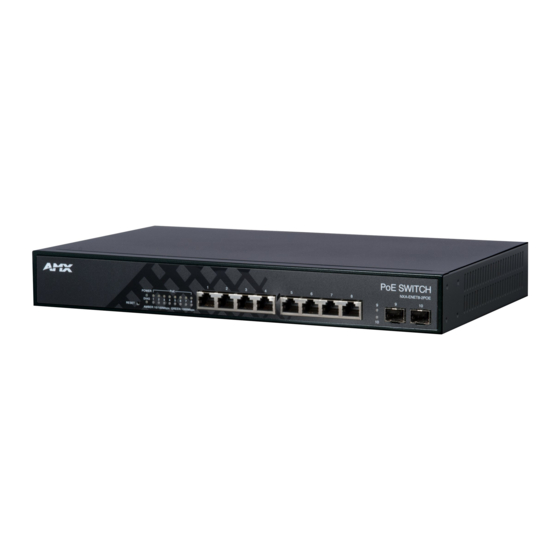
NXA-ENET8-2POE Overview The NXA-ENET8-2POE (FG2178-63) is a Gigabit Ethernet Layer 2 PoE switch with 8 10/100/1000BASE-T ports, and 2 Small Form Factor Pluggable (SFP) transceiver slots, (see FIG. 1, Ports 9-10). The NXA-ENET8-2POE also includes an SNMP-based management agent, which provides in-band access for managing the switch. - Page 16 NXA-ENET8-2POE NXA-ENET8-2POE Hardware Specif ications (Cont.) Network Interface Ports 1-8: RJ-45 connector, auto MDI/MDI-X: • 10BASE-T: RJ-45 (100-ohm, UTP cable; Category 3 or better) • 100BASE-TX: RJ-45 (100-ohm, UTP cable; Category 5 or better) • 1000BASE-T: RJ-45 (100-ohm, UTP cable; Category 5, 5e or better)
-
Page 17: Features
The NXA-ENET8-2POE delivers power to a device using the wire pairs in UTP or STP cable. NOTE: Any RJ-45 port on the NXA-ENET8-2POE can provide up to 30 W of power, but only two ports can deliver 30 W simultaneously to attached devices without exceeding the NXA-ENET8-2POE power budget. -
Page 18: Front Panel Components
For information on the recommended standards for fiber optic cabling, see the Fiber Standards section on page 33. Port and System Status LEDs The NXA-ENET8-2POE includes a LED display panel on the front panel for key system and port indications that simplify installation and network troubleshooting (FIG. 4):... -
Page 19: Reset Button
Powered device connected. No powered device connected. Reset Button If you encounter any malfunctions, such as a hang or nonrecoverable error, you might want to reset the NXA-ENET8-2POE, via the Reset pushbutton on the front panel (FIG. 5): Reset Pushbutton FIG. -
Page 20: Grounding Point
Grounding Point To prevent accidental electrical shock or damage to the NXA-ENET8-2POE, it is recommended that you ground the unit to an earth point by attaching a grounding wire (not supplied) to the grounding point on the rear panel, with a metal screw (FIG. 7). -
Page 21: Network Planning
Gigabit Ethernet port on a plug-in SFP transceiver. In FIG. 9, the NXA-ENET8-2POE is operating as a collapsed backbone for a small LAN. It is providing dedicated 1000 Mbps full- duplex connections to workstations and 100 Mbps full-duplex connections to power users, and 1 Gbps full-duplex connections to servers. -
Page 22: Power Over Ethernet (Poe) Connections
The NXA-ENET8-2POE is an excellent choice for supplying power to connected PoE devices such as web cameras, IP telephones, or access points. In FIG. 10 the NXA-ENET8-2POE is supplying power to three PoE devices. It is also providing dedicated 1000 Mbps full-duplex data connections to these devices. -
Page 23: Remote Connections With Fiber Cable
FIG. 12 Making VLAN Connections The NXA-ENET8-2POE supports VLANs which can be used to organize any group of network nodes into separate broadcast domains. VLANs confine broadcast traffic to the originating group, and can eliminate broadcast storms in large networks. This provides a more secure and cleaner network environment. -
Page 24: Application Notes
Full-duplex operation only applies to point-to-point access (such as when a NXA-ENET8-2POE is attached to a workstation, server, or another switch). When the NXA-ENET8-2POE is connected to a hub, both devices must operate in half-duplex mode. Avoid using flow control on a port connected to a hub unless it is actually required to solve a problem. Otherwise back pressure jamming signals may degrade overall performance for the segment attached to the hub. -
Page 25: Installation
Ethernet Cabling To ensure proper operation when installing the NXA-ENET8-2POE into a network, make sure that the current cables are suitable for 10BASE-T, 100BASE-TX, or 1000BASE-T operation. Check the following criteria against the current installation of your network: Cable type: Un-shielded twisted pair (UTP) or shielded twisted pair (STP) cables with RJ-45 connectors;... -
Page 26: Mounting
Installation Mounting The NXA-ENET8-2POE can be mounted in a standard 19-inch equipment rack or on a desktop or shelf. Mounting instructions for each type of site follow. Rack Mounting Before rack mounting the NXA-ENET8-2POE, pay particular attention to the following factors: Temperature: Since the temperature within a rack assembly may be higher than the ambient room temperature, check that ... -
Page 27: Desktop Or Shelf Mounting
Installation Desktop or Shelf Mounting Attach the four adhesive feet to the bottom of the first NXA-ENET8-2POE (FIG. 18): Attaching the Adhesive Feet FIG. 18 Set the device on a flat surface near an AC power source, making sure there are at least two inches of space on all sides for proper air flow. - Page 28 However, always f irst disconnect the network cable before removing the transceiver. NOTE: The NXA-ENET8-2POE uses lasers to transmit signals over f iber optic cable. The lasers are compliant with the requirements of a Class 1 Laser Product and are inherently eye safe in normal operation. However, you should never look directly at a transmit port when it is powered on.
-
Page 29: Network Connections
Connecting Network Devices The NXA-ENET8-2POE is designed to be connected to 10, 100, or 1000 Mbps network cards in PCs and servers, as well as to other switches and hubs. It may also be connected to remote devices using optional 1000BASE-SX, 1000BASELX, 1000BASE-LH, or 100BASE-FX SFP transceivers. -
Page 30: Network Wiring Connections
Instructions for making connections in the wiring closet with this type of equipment follow: Attach one end of a patch cable to an available port on the NXA-ENET8-2POE, and the other end to the patch panel. If not already in place, attach one end of a cable segment to the back of the patch panel where the punch-down block is located, and the other end to a modular wall outlet. -
Page 31: Connectivity Rules
2 m - 10 km (7 ft - 6.2 miles) Maximum 1000BASE-LH Gigabit Ethernet Cable Length Fiber Size Fiber Bandwidth Maximum Cable Length Connector 9/125 micron single-mode fiber 2 m - 80 km (7 ft - 50 miles) NXA-ENET8-2POE - Instruction Manual... -
Page 32: 100 Mbps Fast Ethernet Collision Domain
Use sequential numbers for cables that originate from the same equipment. Differentiate between racks by naming accordingly. Label each separate piece of equipment. Display a copy of your equipment map, including keys to all abbreviations at each equipment rack. NXA-ENET8-2POE - Instruction Manual... -
Page 33: Cables And Pinouts
Auto-negotiation MDI/MDIX means that every port on the switch will automatically detect the Ethernet cable type being used (straight-through or crossover) and adjust to make a link over that cable. The NXA-ENET8-2POE supports MDI-X on all ports. Therefore either cable type can be used. NOTE: Follow TIA-568B straight-through cabling standards. -
Page 34: Straight-Through Wiring
These tests are specified in the ANSI/TIA/EIATSB-95 Bulletin, “The Additional Transmission Performance Guidelines for 100 Ohm 4-Pair Category 5 Cabling.” Note that when testing your cable installation, be sure to include all patch cables between switches and end devices. NXA-ENET8-2POE - Instruction Manual... -
Page 35: Adjusting Existing Category 5 Cabling To Run 1000Base-T
Optimized for high-power transmission in the 1500 to 1600-nm region, with low loss in the 1550-nm band. G.655 Non-Zero Dispersion-Shifted Fiber Extended long-haul applications. Single-mode, 9/125-micron core Optimized for high-power dense wavelength-division multiplexing (DWDM) operation in the region from 1500 to 1600-nm. NXA-ENET8-2POE - Instruction Manual... -
Page 36: Using The Web Console
Overview The NXA-ENET8-2POE provides a broad range of features for Layer 2 switching. These features can be configured via the NXA- ENET8-2POE’s embedded HTTP Web Console. While the default configuration can be used for most of the features provided by this switch, there are many options that you should configure to maximize the switch's performance for your particular network environment. -
Page 37: Panel Display
This should be done before you permanently install the switch in the network. Follow this procedure: Place the NXA-ENET8-2POE close to the PC that you intend to use for configuration. It helps if you can see the front panel of the switch while working on your PC. -
Page 38: Features
Port Mirroring The NXA-ENET8-2POE can unobtrusively mirror traffic from any port to a monitor port. You can then attach a protocol analyzer or RMON probe to this port to perform traffic analysis and verify connection integrity. Supports 1 session, with up to 10 source ports to one analysis port per session. -
Page 39: Static Addresses
Up to 4K using IEEE 802.1Q, port-based, protocol-based, private VLANs, and voice VLANs, and QinQ tunnel. The NXA-ENET8-2POE supports up to 4096 VLANs. A Virtual LAN is a collection of network nodes that share the same collision domain regardless of their physical location or connection point in the network. -
Page 40: System Defaults
NXA-ENET8-2POE Key Features (Cont.) Qualify of Service The NXA-ENET8-2POE supports Differentiated Services (DiffServ), and DSCP remarking. Differentiated Services (DiffServ) provides policy-based management mechanisms used for prioritizing network resources to meet the requirements of specific traffic types on a per-hop basis. Each packet is classified upon entry into the network based on access lists, DSCP values, or VLAN lists. -
Page 41: Virtual Lans
Using the Web Console NXA-ENET8-2POE System Defaults (Cont.) Function Parameter Default Virtual LANs Default VLAN PVID Acceptable Frame Type All Ingress Filtering Disabled Switchport Mode (Egress Mode) Access Traff ic Prioritization Ingress Port Priority Queue Mode Strict Weighted Round Robin •... -
Page 42: Configuring The Nxa-Enet8-2Poe
Configuring the NXA-ENET8-2POE Conf iguring the NXA-ENET8-2POE Overview This chapter describes all of the basic configuration tasks. Conf iguring System Information Use the System Information Conf iguration page to identify the system by configuring contact information, system name, location of the switch, and time zone offset. -
Page 43: Setting An Ipv6 Address
An IPv6 default gateway must be defined if the management station is located in a different IPv6 segment. An IPv6 default gateway can only be successfully set when a network interface that directly connects to the gateway has been configured on the switch. NXA-ENET8-2POE - Instruction Manual... -
Page 44: Usage Guidelines
IP addresses. The switch will attempt to poll each server in the configured sequence. Click Conf iguration, System, NTP. Enter the IP address of up to five time servers. Click Save. NXA-ENET8-2POE - Instruction Manual... -
Page 45: Configuring Remote Log Messages
Enable remote logging, enter the IP address of the remote server, and specify the type of syslog messages to send. Click Apply. Conf iguring Power Reduction The NXA-ENET8-2POE provides power saving methods including controlling the intensity of LEDs, and powering down the circuitry for port queues when not in use. Controlling LED Intensity Use the LED Power Reduction Conf iguration page to reduces LED intensity during specified hours. -
Page 46: Command Usage
Click Conf iguration, Power Reduction, EEE. Select the circuits which will use EEE. If required, also specify urgent queues which will be powered up once data is queued and the default wakeup time has passed. Click Save. NXA-ENET8-2POE - Instruction Manual... -
Page 47: Configuring Thermal Protection
Port shut down can be prioritized based on assigned temperatures. Click Conf iguration, Thermal Protection. Select the circuits which will use EEE. Set the temperature threshold for each priority, and then assign a priority level to each of the ports. Click Save. NXA-ENET8-2POE - Instruction Manual... -
Page 48: Configuring Port Connections
The following options are supported: Disabled - All power savings mechanisms disabled (default). Enabled - Both link up and link down power savings enabled. ActiPHY - Link down power savings enabled. PerfectReach - Link up power savings enabled. NXA-ENET8-2POE - Instruction Manual... -
Page 49: Configuring Security
15 can be used for an administrator account, privilege level 10 for a standard user account, and privilege level 5 for a guest account. Click Conf iguration, System, Switch, Users Click Add new user. Enter the user name, password, and privilege level. Click Save. NXA-ENET8-2POE - Instruction Manual... -
Page 50: Configuring User Privilege Levels
10 - read and write access of all system functions except for maintenance and debugging 15 - read and write access of all system functions including maintenance and debugging. Click Conf iguration, Security, Switch, Privilege Levels. Set the required privilege level for any software module or functional group. Click Save. NXA-ENET8-2POE - Instruction Manual... -
Page 51: Configuring The Authentication Method For Management Access
NOTE: This guide assumes that RADIUS and TACACS+ servers have already been conf igured to support AAA. The conf iguration of RADIUS and TACACS+ server software is beyond the scope of this guide. Refer to the documentation provided with the RADIUS and TACACS+ server software. NXA-ENET8-2POE - Instruction Manual... -
Page 52: Configuring Ssh
The client and server generate session keys for encrypting and decrypting data. The client and server establish a secure encrypted connection. A padlock icon should appear in the status bar for Internet Explorer 5.x or above, and Mozilla Firefox 2.0.0.0 or above. NXA-ENET8-2POE - Instruction Manual... -
Page 53: Filtering Ip Addresses For Management Access
Access to the switch using from clients using SNMPv3 provides additional security features that cover message integrity, authentication, and encryption; as well as controlling user access to specific areas of the MIB tree. NXA-ENET8-2POE - Instruction Manual... -
Page 54: Configuring Snmp System And Trap Settings
Use the SNMP System Conf iguration page to configure basic settings and traps for SNMP. To manage the switch through SNMP, you must first enable the protocol and configure the basic access parameters. To issue trap messages, the trap function must also be enabled and the destination host specified. SNMP System Configuration FIG. 44 NXA-ENET8-2POE - Instruction Manual... - Page 55 Note: To select a name from this f ield, f irst enter an SNMPv3 user with the same Trap Security Engine ID in the SNMPv3 Users Conf iguration menu (see Conf iguring SNMPV3 Users section on page 54). NXA-ENET8-2POE - Instruction Manual...
-
Page 56: Setting Snmpv3 Community Access Strings
Auth, NoPriv - SNMP communications use authentication, but the data is not encrypted. Auth, Priv - SNMP communications use both authentication and encryption. • Authentication The method used for user authentication. (Options: None, MD5, SHA; Default: MD5) Protocol NXA-ENET8-2POE - Instruction Manual... -
Page 57: Configuring Snmpv3 Groups
SNMPv3 Communities menu. For USM, the security names displayed are based on the those configured in the SNMPv3 Users Conf iguration menu. Enter a group name. Note that the views assigned to a group must be specified on the SNMP Accesses Conf iguration menu (see page 56). Click Save. NXA-ENET8-2POE - Instruction Manual... -
Page 58: Configuring Snmpv3 Views
The configured view for write access. (Range: 1-32 characters, ASCII characters 33-126 only) Click Conf iguration, Security, Switch, SNMP, Access. Click Add New Access to create a new entry. Specify the group name, security settings, read view, and write view. Click Save. NXA-ENET8-2POE - Instruction Manual... -
Page 59: Configuring Port Limit Controls
Limit Reached: Indicates that the limit is reached on this port. This state can only be shown if Action is set to None or Trap. Shutdown: Indicates that the port is shut down by the Limit Control module. This state can only be shown if Action is set to Shutdown or Trap & Shutdown. NXA-ENET8-2POE - Instruction Manual... -
Page 60: Configuring Authentication Through Network Access Servers
Sets the time period after which a connected client must be re-authenticated. Range: 1-3600 seconds; Default: Period 3600 seconds • EAPOL Timeout Sets the time the switch waits for a supplicant response during an authentication session before retransmitting a Request Identify EAPOL packet. (Range: 1-255 seconds; Default: 30 seconds) NXA-ENET8-2POE - Instruction Manual... - Page 61 Note: For trouble-shooting VLAN assignments, use the Monitor > VLANs >VLAN Membership and VLAN Port pages. These pages show which modules have (temporarily) overridden the current Port VLAN conf iguration. See the Guest VLAN Operation section on page 63 for details. NXA-ENET8-2POE - Instruction Manual...
- Page 62 RADIUS user can be used by anyone. Also, only the MD5-Challenge method is supported. The maximum number of clients that can be attached to a port can be limited using the Port Security Limit Control functionality. NXA-ENET8-2POE - Instruction Manual...
- Page 63 The RADIUS server verifies the client credentials and responds with an accept or reject packet. If authentication is successful, the switch allows the client to access the network. Otherwise, network access is denied and the port remains blocked. NXA-ENET8-2POE - Instruction Manual...
-
Page 64: Usage Guidelines
While a port has an assigned dynamic QoS profile, any manual QoS configuration changes only take effect after all users have logged off the port. NXA-ENET8-2POE - Instruction Manual... -
Page 65: Radius Attributes Used In Identifying A Vlan Id
When port status changes to down, all MAC addresses are cleared from the secure MAC address table. Static VLAN assignments are not restored. Click Conf iguration, Security, Network, NAS. Modify the required attributes. Click Save. NXA-ENET8-2POE - Instruction Manual... -
Page 66: Filtering Traffic With Access Control Lists
An Access Control List (ACL) is a sequential list of permit or deny conditions that apply to IP addresses, MAC addresses, or other more specific criteria. The NXA-ENET8-2POE tests ingress packets against the conditions in an ACL one by one. A packet will be accepted as soon as it matches a permit rule, or dropped as soon as it matches a deny rule. -
Page 67: Configuring Rate Limiters
Conf iguration menu (see the Conf iguring Authentication Through Network Access Servers section on page 58). Access Control List Configuration FIG. 55 Access Control List Conf iguration Parameters Access Control List Conf iguration • Ingress Any port, port identifier, or policy. Port • Frame Type The type of frame to match. NXA-ENET8-2POE - Instruction Manual... - Page 68 (Options: Any - any value is allowed, 0 - RARP frames where THA is not equal to the DMAC address, 1 - RARP frames where THA is equal to the DMAC address; Default: Any) NXA-ENET8-2POE - Instruction Manual...
- Page 69 (Options: Any - any value is allowed, Non-zero - IPv4 frames with a TTL field greater than zero must match this entry, Zero - IPv4 frames with a TTL field greater than zero must not match this entry; Default: Any) NXA-ENET8-2POE - Instruction Manual...
-
Page 70: Usage Guidelines
Ethernet, matches this entry when ARP/RARP protocol address space setting is equal to IP (0x800) IPv4 frames (based on destination MAC address, protocol type, TTL, IP fragment, IP option flag, source/destination IP, VLAN ID, VLAN priority) NXA-ENET8-2POE - Instruction Manual... -
Page 71: Qce Modification Buttons
If DHCP snooping is enabled globally, all DHCP packets are forwarded for a trusted port. If the received packet is a DHCP ACK message, a dynamic DHCP snooping entry is also added to the binding table. NXA-ENET8-2POE - Instruction Manual... -
Page 72: Additional Considerations When The Switch Itself Is A Dhcp Client
Click Conf iguration, Security, Network, DHCP, Relay. Enable the DHCP relay function, specify the DHCP server’s IP address, enable Option 82 information mode, and set the policy by which to handle relay information found in client packets. Click Save. NXA-ENET8-2POE - Instruction Manual... -
Page 73: Configuring Ip Source Guard
IP traffic on that port, except for DHCP packets. Click Conf iguration, Security, Network, IP Source Guard, Conf iguration. Enable or disable IP Source Guard globally and for any given ports. Set the maximum number of dynamic clients for any port. Click Save. NXA-ENET8-2POE - Instruction Manual... -
Page 74: Configuring Static Bindings For Ip Source Guard
ARP Inspection is enabled globally again. ARP Inspection uses the DHCP snooping bindings database for the list of valid IP-to-MAC address bindings. NOTE: DHCP snooping must be enabled for dynamic clients to be learned automatically. NXA-ENET8-2POE - Instruction Manual... -
Page 75: Configuring Global And Port Settings For Arp Inspection
ARP table. If no static entry matches the packets, then the DHCP snooping bindings database determines their validity. Click Conf iguration, Network, Security, ARP Inspection, Static Table. Click Add new entry. Enter the required bindings for a given port. Click Save. NXA-ENET8-2POE - Instruction Manual... -
Page 76: Specifying Authentication Servers
TACACS+ server software. Click Conf iguration, Security, AAA. Configure the authentication method for management client types, the common server timing parameters, and address, UDP port, and secret key for each required RADIUS or TACACS+ server. Click Save. NXA-ENET8-2POE - Instruction Manual... -
Page 77: Creating Trunk Groups
STP, VLAN, and IGMP settings can only be made for the entire trunk. Conf iguring Static Trunks Use the Aggregation Mode Conf iguration page to configure the aggregation mode and members of each static trunk group. Static Trunk Configuration FIG. 63 NXA-ENET8-2POE - Instruction Manual... -
Page 78: Usage Guidelines
Aggregation Mode Configuration also applies to LACP (see the Conf iguring LACP section on page 77). Click Conf iguration, Aggregation, Static. Select one or more load-balancing methods to apply to the configured trunks. Assign port members to each trunk that will be used. Click Save. NXA-ENET8-2POE - Instruction Manual... -
Page 79: Configuring Lacp
Specify the LACP Admin Key to restrict a port to a specific LAG. Set at least one of the ports in each LAG to Active initiation mode, either at the near end or far end of the trunk. Click Save. NXA-ENET8-2POE - Instruction Manual... -
Page 80: Configuring Loop Protection
Enable loop protection globally, set the transmission interval for LPPDUs, and set the shutdown time for ports with a detected loop. Enable loop protection on the ports where required, set the response to a detected loop, and specify whether the port actively sends LPPDUs or just monitors for looped LPPDUs. Click Save. NXA-ENET8-2POE - Instruction Manual... -
Page 81: Configuring The Spanning Tree Algorithm
Region Name, Revision Level and Configuration Digest – see the Conf iguring Multiple Spanning Trees section on page 82. An MST Region may contain multiple MSTP Instances. An Internal Spanning Tree (IST) is used to connect all the MSTP switches within an MST region. NXA-ENET8-2POE - Instruction Manual... -
Page 82: Configuring Global Settings For Sta
(Note that lower numeric values indicate higher priority.) Default: 128 Range: 0-240, in steps of 16 Options: 0, 16, 32, 48, 64, 80, 96, 112, 128, 144, 160, 176, 192, 208, 224, 240 NXA-ENET8-2POE - Instruction Manual... -
Page 83: Command Usage
VLAN instance assignments. Be careful when switching between spanning tree modes. Changing modes stops all spanning-tree instances for the previous mode and restarts the system in the new mode, temporarily disrupting user traffic. Click Conf iguration, Spanning Tree, Bridge Settings. Modify the required attributes. Click Save. NXA-ENET8-2POE - Instruction Manual... -
Page 84: Configuring Multiple Spanning Trees
Click Conf iguration, Spanning Tree, MSTI Mapping. Enter the VLAN group to add to the instance in the VLANs Mapped column. Note that the specified member does not have to be a configured VLAN. Click Save. NXA-ENET8-2POE - Instruction Manual... -
Page 85: Configuring Spanning Tree Bridge Priorities
Use the STP CIST Port Conf iguration page to configure STA attributes for interfaces when the spanning tree mode is set to STP or RSTP, or for interfaces in the CIST. STA interface attributes include path cost, port priority, edge port (for fast forwarding), automatic detection of an edge port, and point-to-point link type. STP/RSTP/CIST Port Configuration FIG. 72 NXA-ENET8-2POE - Instruction Manual... - Page 86 (References to ports in this section means interfaces, which includes both ports and trunks.) Click Conf iguration, Spanning Tree, CIST Ports. Modify the required attributes. Click Save. NXA-ENET8-2POE - Instruction Manual...
-
Page 87: Path Costs
Full Duplex 10,000 Trunk 5,000 Conf iguring MSTI Interfaces Use the MSTI Ports Conf iguration page to configure STA attributes for interfaces in a specific MSTI, including path cost, and port priority. MSTI Port Configuration FIG. 73 NXA-ENET8-2POE - Instruction Manual... -
Page 88: Multicast Vlan Registration
MVR VLAN when it forwards an IGMP report or join message from an attached host requesting any of the designated multicast services supported by the MVR VLAN. NXA-ENET8-2POE - Instruction Manual... -
Page 89: General Configuration Guidelines For Mvr
In this case (Layer 2) IGMP Query can be used to actively ask the attached hosts if they want to receive a specific multicast service. IGMP Query thereby identifies the ports containing hosts requesting to join the service and sends data out to those ports only. NXA-ENET8-2POE - Instruction Manual... -
Page 90: Configuring Global And Port-Related Settings For Igmp Snooping
IGMP querier (i.e., a multicast router/switch). This interface will then join all the current multicast groups supported by the attached router/switch to ensure that multicast traffic is passed to all appropriate interfaces within the switch. NXA-ENET8-2POE - Instruction Manual... -
Page 91: Configuring Vlan Settings For Igmp Snooping And Query
If the QRV exceeds 7, the maximum value of the QRV field, the robustness value is set to zero, meaning that this device will not advertise a QRV in any query messages it subsequently sends. NXA-ENET8-2POE - Instruction Manual... -
Page 92: Configuring Igmp Filtering
Click Add New Filtering Group to display a new entry in the table. Select the port to which the filter will be applied. Enter the IP address of the multicast service to be filtered. Click Save. NXA-ENET8-2POE - Instruction Manual... -
Page 93: Mld Snooping
When a host joins a multicast group to which no other host belongs, it sends unsolicited multicast listener reports to that group. When the last host in a particular multicast group leaves, it sends an unsolicited multicast listener done report to the all-routers address (FF02::2) for MLDv1. NXA-ENET8-2POE - Instruction Manual... -
Page 94: Configuring Vlan Settings For Mld Snooping And Query
IPv6 address as the query source address. The querier will not start or will disable itself after having started if it detects an IPv6 multicast router on the network. NXA-ENET8-2POE - Instruction Manual... -
Page 95: Configuring Mld Filtering
Click Add New Filtering Group to display a new entry in the table. Select the port to which the filter will be applied. Enter the IP address of the multicast service to be filtered. Click Save. NXA-ENET8-2POE - Instruction Manual... -
Page 96: Link Layer Discovery Protocol
CDP awareness enabled, all CDP frames are terminated by the switch. When CDP awareness for a port is disabled, the CDP information is not removed immediately, but will be removed when the hold time is exceeded. NXA-ENET8-2POE - Instruction Manual... -
Page 97: Configuring Lldpmed Tlvs
IP phones and network switches. The LLDP-MED TLVs advertise information such as network policy, power, inventory, and device location details. Both LLDP and LLDP-MED information can be used by SNMP applications to simplify troubleshooting, enhance network management, and maintain an accurate network topology. LLDPMED Configuration FIG. 83 NXA-ENET8-2POE - Instruction Manual... - Page 98 Room no. - Room number. (Example: 450F) Place type - Place type. (Example: Office) Postal community name - Postal community name. (Example: Leonia) P.O. Box - Post office box (P.O. BOX). (Example: 12345) Additional code - Additional code. (Example: 1320300003) NXA-ENET8-2POE - Instruction Manual...
- Page 99 L2 Priority - Layer 2 priority used for the specified application type. L2 Priority may specify one of eight priority levels (0 - 7), as defined by IEEE 802.1D-2004. A value of 0 represents use of the default priority as defined in IEEE 802.1D-2004. NXA-ENET8-2POE - Instruction Manual...
-
Page 100: Power Over Ethernet
Reserved Power - Ports are shut down when total reserved powered exceeds the amount of power that the power supply can deliver. In this mode the port power is not turned on if the PD requests more power than available from the power supply. NXA-ENET8-2POE - Instruction Manual... -
Page 101: Command Usage
PoE mode) Command Usage The NXA-ENET8-2POE can provide DC power to a wide range of connected devices, eliminating the need for an additional power source and cutting down on the amount of cables attached to each device. Once configured to supply power, an automatic detection process is initialized by the switch that is authenticated by a PoE signature from the connected device. -
Page 102: Configuring The Mac Address Table
Specify the way in which MAC addresses are learned on any port. Add any required static MAC addresses by clicking the Add New Static Entry button, entering the VLAN ID and MAC address, and marking the ports to which the address is to be mapped. Click Save. NXA-ENET8-2POE - Instruction Manual... -
Page 103: Ieee 802.1Q Vlans
Change the ports assigned to the default VLAN (VLAN 1) if required. To configure a new VLAN, click Add New VLAN, enter the VLAN ID, and then mark the ports to be assigned to the new group. Click Save. NXA-ENET8-2POE - Instruction Manual... -
Page 104: Configuring Vlan Attributes For Port Members
VLAN tags. When forwarding a frame from this switch along a path that does not contain any VLAN-aware devices (including the destination host), the switch should first strip off the VLAN tag before forwarding the frame. NXA-ENET8-2POE - Instruction Manual... -
Page 105: Configuring Private Vlans
Ports within a private VLAN (PVLAN) are isolated from other ports which are not in the same PVLAN. Port Isolation can be used to prevent communications between ports within the same PVLAN. An isolated port cannot forward any unicast, multicast, or broadcast traffic to any other ports in the same PVLAN. NXA-ENET8-2POE - Instruction Manual... -
Page 106: Configuring Mac-Based Vlans
Then map the protocol for each interface to the appropriate VLAN using the Configure Interface (Add) page. When MAC-based, IP subnet-based, and protocol-based VLANs are supported concurrently, priority is applied in this sequence, and then port-based VLANs last. NXA-ENET8-2POE - Instruction Manual... -
Page 107: Configuring Protocol Vlan Groups
The name assigned to the Protocol VLAN Group. This name must be a unique 16-character long string which consists of a combination of alphabetic characters (a-z or A-Z) or integers (0-9). • VLAN ID VLAN to which matching protocol traffic is forwarded. (Range: 1-4095) • Port Members Ports assigned to this protocol VLAN. NXA-ENET8-2POE - Instruction Manual... -
Page 108: Command Usage
VLAN (see "Setting an IPv4 Address" on page 44), the MVR VLAN (see the Multicast VLAN Registration section on page 86), or the native VLAN assigned to any port (see the Conf iguring VLAN Attributes For Port Members section on page 102). NXA-ENET8-2POE - Instruction Manual... -
Page 109: Configuring Telephony Oui
Use the Voice VLAN OUI Table to identify VoIP devices attached to the switch. VoIP devices can be identified by the manufacturer’s Organizational Unique Identifier (OUI) in the source MAC address of received packets. Voice VLAN OUI Table FIG. 94 NXA-ENET8-2POE - Instruction Manual... -
Page 110: Quality Of Service
Sets classification mode for tagged frames on this port: Disabled - Uses the default QoS class and DP level for tagged frames. (This is the default.) Enabled - Uses the mapped versions of PCP and DEI for tagged frames. NXA-ENET8-2POE - Instruction Manual... -
Page 111: Configuring Tag Classification For Tagged Frames
Click on any of the entries in the Port field to configure egress queue mode, queue shaper (rate and access to excess bandwidth), and port shaper. Showing An Overview of the Queue Mode and Weight Used by Egress Ports Displaying Egress Port Schedulers FIG. 97 NXA-ENET8-2POE - Instruction Manual... -
Page 112: Configuring The Scheduler Mode, Egress Queue Mode, Queue Shaper, And Port Shaper Used By Egress Ports
Click on any enter under the Port field to configure the Port Scheduler and Shaper. Conf iguring the Scheduler Mode, Egress Queue Mode, Queue Shaper, and Port Shaper Used by Egress Ports Configuring Egress Port Schedulers and Shapers FIG. 98 Click Conf iguration, QoS, Port Scheduler. NXA-ENET8-2POE - Instruction Manual... -
Page 113: Configuring Egress Port Shaper
Refer to the description of these parameters in the Conf iguring Egress Port Scheduler section on page 109. Click Conf iguration, QoS, Port Shaper. Click on any enter under the Port field to configure the Port Scheduler and Shaper. NXA-ENET8-2POE - Instruction Manual... -
Page 114: Configuring Port Remarking Mode
Shows the tag remarking mode used by this port: Classified - Uses classified PCP (Priority Code Point or User Priority) and DEI (Drop Eligible Indicator) values. Default - Uses default PCP/DEI values. Mapped - Uses mapped versions of QoS class and drop precedence level. NXA-ENET8-2POE - Instruction Manual... -
Page 115: Configuring The Tag Remarking Mode
The remapped DSCP value is always taken from the DSCP Translation table, Egress Remap DP0 field (see page 114). Click Conf iguration, QoS, Port DSCP. Set the required ingress translation and egress re-writing parameters. Click Save. NXA-ENET8-2POE - Instruction Manual... -
Page 116: Configuring Dscp-Based Qos Ingress Classification
• Egress Remap DP1 Re-maps DP1 field to selected DSCP value. DP1 indicates a drop precedence with a high priority. Click Conf iguration, QoS, DSCP Translation. Set the required ingress translation and egress re-mapping parameters. Click Save. NXA-ENET8-2POE - Instruction Manual... -
Page 117: Configuring Dscp Classification
Shows the mapping options for QoS class values and DP (drop precedence) levels. • DSCP DSCP value. (Range: 0-63) Click Conf iguration, QoS, DSCP Classif ication. Map key DSCP values to a corresponding QoS class and drop precedence level. Click Save. NXA-ENET8-2POE - Instruction Manual... -
Page 118: Configuring Qos Control Lists
VLAN identifier. (Options: Any, Specific (1-4095), Range; Default: Any) • PCP Priority Code Point (User Priority). (Options: a specific value of 0, 1, 2, 3, 4, 5, 6, 7, a range of 0-1, 2-3, 4-5, 6-7, 0-3, 4-7, or Any; Default: 0) NXA-ENET8-2POE - Instruction Manual... - Page 119 Click the button to add a new QCE, or use the other QCE modification buttons to specify the editing action (i.e., edit, delete, or moving the relative position of entry in the list). When editing an entry on the QCE Configuration page, specify the relevant criteria to be matched, and the response to a match. Click Save. NXA-ENET8-2POE - Instruction Manual...
-
Page 120: Qce Modification Buttons
Select the control rate as a function of 2n pps (i.e., a value with no suffix for the unit of measure) or a rate in Kpps (i.e., a value marked with the suffix K). Click Save. NXA-ENET8-2POE - Instruction Manual... -
Page 121: Configuring Port Mirroring
Using UPnP under Windows XP - To access or manage the switch with the aid of UPnP under Windows XP, open My Network Places in the Explore file manager. An entry for NXA-ENET8-2PoE will appear in the list of discovered devices. - Page 122 Due to the unreliable nature of UDP, the switch sends SSDP messages periodically at the interval one-half of the advertising duration minus 30 seconds. (Range: 100-86400 seconds; Default: 100 seconds) Click Conf iguration, UPnP. Enable or disable UPnP, then set the TTL and advertisement values. Click Save. NXA-ENET8-2POE - Instruction Manual...
-
Page 123: Monitoring The Nxa-Enet8-2Poe
Monitoring the NXA-ENET8-2POE Monitoring the NXA-ENET8-2POE Overview This chapter describes how to monitor all of the basic functions, configure or view system logs, and how to view traffic status or the address table. Displaying Basic Information About the System You can use the Monitor/System menu to display a basic description of the switch, log messages, or statistics on traffic used in managing the switch. -
Page 124: Displaying Cpu Utilization
Monitoring the NXA-ENET8-2POE Displaying CPU Utilization Use the CPU Load page to display information on CPU utilization. CPU Load FIG. 112 The load is averaged over the last 100ms, 1sec and 10 seconds intervals. The last 120 samples are graphed. -
Page 125: Displaying Log Details
Monitoring the NXA-ENET8-2POE Click Monitor, System, Log. Specify the message level to display, the starting message ID, and the number of messages to display per page. Use Auto-refresh to automatically refresh the page at regular intervals, Refresh to update system log entries starting from the current entry ID, or Clear to flush all system log entries. -
Page 126: Displaying Information About Ports
Monitoring the NXA-ENET8-2POE Displaying Information About Ports You can use the Monitor/Port menu to display a graphic image of the front panel which indicates the connection status of each port, basic statistics on the traffic crossing each port, the number of packets processed by each service queue, or detailed statistics on port traffic. -
Page 127: Displaying Qcl Status
Monitoring the NXA-ENET8-2POE Displaying QCL Status Use the QoS Control List Status page to show the QCE entries configured for different users or software modules, and whether or not there is a conflict. QoS Control List Status FIG. 119 QoS Control List Status parameters •... -
Page 128: Displaying Detailed Port Statistics
Monitoring the NXA-ENET8-2POE Displaying Detailed Port Statistics Use the Detailed Port Statistics page (click Monitor, Ports, Detailed Statistics) to display detailed statistics on network traffic. This information can be used to identify potential problems with the switch (such as a faulty port or unusually heavy loading). All values displayed have been accumulated since the last system reboot, and are shown as counts per second. -
Page 129: Displaying Information About Security Settings
Monitoring the NXA-ENET8-2POE Detailed Port Statistics parameters (Cont.) • Receive/Transmit Size The number of received and transmitted packets (good and bad) split into categories based on their Counters respective frame sizes. • Receive/Transmit The number of received and transmitted packets per input and output queue. -
Page 130: Displaying Information About Switch Settings For Port Security
Monitoring the NXA-ENET8-2POE Displaying Information About Switch Settings For Port Security Use the Port Security Switch Status page to show information about MAC address learning for each port, including the software module requesting port security services, the service state, the current number of learned addresses, and the maximum number of secure addresses allowed. -
Page 131: Displaying Information About Learned Mac Addresses
Monitoring the NXA-ENET8-2POE Displaying Information About Learned Mac Addresses Use the Port Security Port Status page to show the entries authorized by port security services, including MAC address, VLAN ID, time added to table, age, and hold state. Port Security Port Status FIG. -
Page 132: Displaying Port Statistics For 802.1X Or Remote Authentication Service
Monitoring the NXA-ENET8-2POE Displaying Port Statistics For 802.1x Or Remote Authentication Service Use the NAS Statistics Port selection page (click Monitor, Security, Network, NAS, Port) to display authentication statistics for the selected port – either for 802.1X protocol or for the remote authentication server depending on the authentication method. This page provides detailed NAS statistics for a specific switch port running EAPOL-based IEEE 802.1X authentication. - Page 133 Monitoring the NXA-ENET8-2POE NAS Statistics Port parameters (Cont.) Port Counters (Cont.) Transmit EAPOL Counters (Cont.) • Access Challenges 802.1X-based: Counts the number of times that the switch receives the first request from the backend server following the first response from the supplicant. Indicates that the backend server has communication with the switch.
-
Page 134: Displaying Acl Status
Monitoring the NXA-ENET8-2POE Displaying ACL Status Use the ACL Status page to show the status for different security modules which use ACL filtering, including ingress port, frame type, and forwarding action. Each row describes a defined ACE (see the Filtering Traff ic With Access Control Lists section on page 64). -
Page 135: Displaying Statistics For Dhcp Snooping
Monitoring the NXA-ENET8-2POE Displaying Statistics for DHCP Snooping Use the DHCP Snooping Port Statistics page to show statistics for various types of DHCP protocol packets. DHCP Snooping Port Statistics FIG. 127 DHCP Snooping Port Statistics parameters • Rx/Tx Discover The number of discover (option 53 with value 1) packets received and transmitted. -
Page 136: Displaying Dhcp Relay Statistics
Monitoring the NXA-ENET8-2POE Displaying DHCP Relay Statistics Use the DHCP Relay Statistics page (click Monitor, DHCP, Relay Statistics) to display statistics for the DHCP relay service supported by this switch and DHCP relay clients. DHCP Relay Statistics FIG. 128 DHCP Relay Statistics parameters Server Statistics •... -
Page 137: Displaying Mac Address Bindings For Arp Packets
Monitoring the NXA-ENET8-2POE Displaying MAC Address Bindings for ARP Packets Open the Dynamic ARP Inspection Table (click Monitor, Security, Network, ARP Inspection) to display address entries sorted first by port, then VLAN ID, MAC address, and finally IP address. Dynamic ARP Inspection Table FIG. -
Page 138: Displaying Statistics For Configured Authentication Servers
Monitoring the NXA-ENET8-2POE Displaying Statistics For Conf igured Authentication Servers Use the RADIUS Details page (click Monitor, Authentication, RADIUS Details) to display statistics for configured authentication and accounting servers. The statistics map closely to those specified in RFC4668 - RADIUS Authentication Client MIB. - Page 139 Monitoring the NXA-ENET8-2POE RADIUS Details parameters (Cont.) Other Info • State The current state of the server. This field takes one of the following values: Disabled - The server is disabled. Not Ready - The server is enabled, but IP communication is not yet up and running.
-
Page 140: Displaying Information On Lacp
Monitoring the NXA-ENET8-2POE Displaying Information on LACP Use the monitor pages for LACP to display information on LACP configuration settings, the functional status of participating ports, and statistics on LACP control packets. Displaying an Overview of LACP Groups Use the LACP System Status page (click Monitor, LACP, System Status) to display an overview of LACP groups. -
Page 141: Displaying Lacp Port Statistics
Monitoring the NXA-ENET8-2POE Displaying LACP Port Statistics Use the LACP Port Statistics page (click Monitor, LACP, Port Statistics) to display statistics on LACP control packets crossing on each port. LACP Port Statistics FIG. 135 LACP Port Statistics parameters • Port Port Identifier. -
Page 142: Displaying Information On The Spanning Tree
Monitoring the NXA-ENET8-2POE Displaying Information On the Spanning Tree Use the monitor pages for Spanning Tree to display information on spanning tree bridge status, the functional status of participating ports, and statistics on spanning tree protocol packets. Displaying Bridge Status for STA Use the Bridge Status page to display STA information on the global bridge (i.e., this switch) and individual ports. -
Page 143: Displaying Port Status For Sta
Monitoring the NXA-ENET8-2POE Bridge Status parameters (Cont.) CIST Ports & Aggregations State (Cont.) • Point2Point Indicates a connection to exactly one other bridge. The flag may be automatically computed or explicitly configured. The point-to-point properties of a port affect how fast it can transition RSTP states. -
Page 144: Displaying Port Statistics For Sta
Monitoring the NXA-ENET8-2POE Spanning Tree Port Status parameters (Cont.) • CIST State Displays current state of this port within the Spanning Tree: Blocking - Port receives STA configuration messages, but does not forward packets. Learning - Port has transmitted configuration messages for an interval set by the Forward Delay parameter without receiving contradictory information. -
Page 145: Displaying Mvr Group Information
Monitoring the NXA-ENET8-2POE Displaying MVR Group Information Use the MVR Group Information page (click Monitor, MVR, Group Information.) to display statistics for IGMP protocol messages used by MVR; and to shows information about the interfaces associated with multicast groups assigned to the MVR VLAN. -
Page 146: Showing Igmp Snooping Group Information
Monitoring the NXA-ENET8-2POE IGMP Snooping Status parameters (Cont.) Statistics (Cont.) • V3 Reports Received The number of received IGMP Version 3 reports. • V2 Leaves Received The number of received IGMP Version 2 leave reports. Router Port • Port Port Identifier. -
Page 147: Showing Mld Snooping Information
Monitoring the NXA-ENET8-2POE Showing MLD Snooping Information Use the MLD Snooping pages to display MLD snooping statistics, port members of each service group, and information on source- specific groups. Showing MLD Snooping Status Use the IGMP Snooping Status page (Monitor, MLD Snooping) to display MLD querier status and snooping statistics for each VLAN carrying multicast traffic, and the ports connected to an upstream multicast router/switch. -
Page 148: Showing Ipv6 Ssm Information
Monitoring the NXA-ENET8-2POE Showing IPV6 SSM Information Use the MLD SSM Information page (click Monitor, MLD Snooping, IPv6 SSM Information) to display MLD Source-Specific Information including group, filtering mode (include or exclude), source address, and type (allow or deny). MLD SSM Information FIG. -
Page 149: Displaying Lldp-Med Neighbor Information
Monitoring the NXA-ENET8-2POE Displaying LLDP-MED Neighbor Information Use the LLDP-MED Neighbor Information page (click Monitor, LLDP, LLDP-MED Neighbors) to display information about a remote device connected to a port on this switch which is advertising LLDP-MED TLVs, including network connectivity device, endpoint device, capabilities, application type, and policy. -
Page 150: Displaying Lldp Neighbor Poe Information
Monitoring the NXA-ENET8-2POE LLDP-MED Neighbor Information parameters (Cont.) • VLAN ID The VLAN identifier (VID) for the port as defined in IEEE 802.1Q-2003. A value of 1 through 4094 is used to define a valid VLAN ID. A value of 0 (Priority Tagged) is used if the device is using priority tagged frames as defined by IEEE 802.1Q-2003, meaning that only the IEEE 802.1D priority level is significant and the default PVID of the... -
Page 151: Displaying Lldp Port Statistics
Monitoring the NXA-ENET8-2POE LLDP Neighbors EEE Information parameters (Cont.) • Echo Rx Tw The link partner's Echo Rx Tw value. • Resolved Tx Tw The resolved Tx Tw for this link (not the link partner). The resolved value that is the actual tx wakeup time used for this link (based on EEE information exchanged via LLDP). -
Page 152: Displaying Poe Status
Monitoring the NXA-ENET8-2POE Displaying PoE Status Use the Power Over Ethernet Status page (click Monitor, PoE) to display the status for all PoE ports, including the PD class, requested power, allocated power, power and current used, and PoE priority. Power Over Ethernet Status FIG. -
Page 153: Displaying Information About Vlans
Monitoring the NXA-ENET8-2POE Displaying Information About VLANs Use the monitor pages for VLANs to display information about the port members of VLANs, and the VLAN attributes assigned to each port. VLAN Membership Use the VLAN Membership Status page to display the current port members for all VLANs configured by a selected software module. -
Page 154: Displaying Information About Mac-Based Vlans
Monitoring the NXA-ENET8-2POE VLAN Port Status parameters (Cont.) • UVID Shows the untagged VLAN ID. A port's UVID determines the packet's behavior at the egress side. If the VID of Ethernet frames leaving a port match the UVID, these frames will be sent untagged. -
Page 155: Performing Basic Diagnostics
Performing Basic Diagnostics Performing Basic Diagnostics Overview This chapter describes how to test network connectivity using Ping for IPv4 or IPv6, and how to test network cables. Pinging an IPV4 or IPV6 Address The Ping page is used to send ICMP echo request packets to another node on the network to determine if it can be reached. Ping page FIG. -
Page 156: Performing System Maintenance
FIG. 162 Upgrading Firmware Use the Software Upload page to upgrade the switch’s system firmware by specifying a file provided by AMX. You can download firmware files for your switch from the Tech Support section of the AMX web site: Software Upload FIG. -
Page 157: Managing Configuration Files
Performing System Maintenance Managing Conf iguration Files Use the Maintenance Conf iguration pages to save the current configuration to a file on your computer, or to restore previously saved configuration settings to the switch. Saving Conf iguration Settings Use the Conf iguration Download page to save the current configuration settings to a file on your local management station. Configuration Download FIG. -
Page 158: Appendix A: Troubleshooting
Appendix A: Troubleshooting Appendix A: Troubleshooting Diagnosing LED Indicators LED Indicators LED Status Action PWR LED is Off • Check connections between the switch, the power cord, and the wall outlet. • Contact your dealer for assistance. DIAG LED is Flashing Amber •... -
Page 159: Appendix B: Software Specifications
Appendix B: Software Specifications Appendix B: Software Specif ications Software Features Software Features Management Authentication Local, RADIUS, TACACS+, AAA, Port Authentication (802.1X), HTTPS, SSH, Port Security, IP Filter, DHCP Snooping Client Access Control Access Control Lists (128 rules per system), Port Authentication (802.1X), MAC Authentication, Port Security, DHCP Snooping, IP Source Guard, ARP Inspection Port Configuration... -
Page 160: Standards
Appendix B: Software Specifications Standards Standards ANSI/TIA-1057 LLDP for Media Endpoint Discovery - LLDP-MED IEEE 802.1AB Link Layer Discovery Protocol IEEE-802.1ad Provider Bridge IEEE 802.1D-2004 Spanning Tree Algorithm and traffic priorities • Spanning Tree Protocol • Rapid Spanning Tree Protocol •... -
Page 161: Management Information Bases
Appendix B: Software Specifications Management Information Bases Management Information Bases Bridge MIB (RFC 4188) DHCP Option for Civic Addresses Configuration Information (RFC 4776) Differentiated Services MIB (RFC 3289) DNS Resolver MIB (RFC 1612) Entity MIB version 3 (RFC 4133) Ether-like MIB (RFC 3635) Extended Bridge MIB (RFC 2674) Extensible SNMP Agents MIB (RFC 2742) Forwarding Table MIB (RFC 2096) -
Page 162: Appendix C: Gnu License Information
Appendix C: GNU License Information Appendix C: GNU License Information Overview This product includes copyrighted third-party software subject to the terms of the GNU General Public License (GPL), GNU Lesser General Public License (LGPL), or other related free software licenses. The GPL code used in this product is distributed WITHOUT ANY WARRANTY and is subject to the copyrights of one or more authors. - Page 163 Appendix C: GNU License Information These requirements apply to the modified work as a whole. If identifiable sections of that work are not derived from the Program, and can be reasonably considered independent and separate works in themselves, then this License, and its terms, do not apply to those sections when you distribute them as separate works.
- Page 164 Appendix C: GNU License Information NO WARRANTY BECAUSE THE PROGRAM IS LICENSED FREE OF CHARGE, THERE IS NO WARRANTY FOR THE PROGRAM, TO THE EXTENT PERMITTED BY APPLICABLE LAW. EXCEPT WHEN OTHERWISE STATED IN WRITING THE COPYRIGHT HOLDERS AND/OR OTHER PARTIES PROVIDE THE PROGRAM "AS IS"...
- Page 165 © 2016 Harman. All rights reserved. Metreau, NetLinx, AMX, AV FOR AN IT WORLD, HARMAN, and their respective logos are registered trademarks of Last Revised: HARMAN. Oracle, Java and any other company or brand name referenced may be trademarks/registered trademarks of their respective companies.
Need help?
Do you have a question about the NXA-ENET8-2POE and is the answer not in the manual?
Questions and answers