Table of Contents
Advertisement
Advertisement
Chapters
Table of Contents

Related Manuals for AND Check Weighing Indicator AD-4404


Summary of Contents for AND Check Weighing Indicator AD-4404
- Page 1 ふ Check Weighing Indicator WM : PD4000489...
- Page 2 This is a hazard alert mark. This mark informs you about the operation of the product. Note This manual is subject to change without notice at any time to improve the product. No part of this manual may be photocopied, reproduced, or translated into another language without the prior written consent of the A&D Company.
-
Page 3: Table Of Contents
Contents Contents Contents Contents Compliance..................5 1.1.1. Compliance with FCC rules ............5 1.1.2. Compliance with European Directives........5 Outline and Features ................. 6 2.1. Precautions..................7 2.2. Front Panel ..................8 2.2.1. Keys ..................9 2.2.2. Symbols................... 10 2.3. Rear Panel................... - Page 4 7.1.2. Editing a Code in the Sub-display ........... 44 7.2. The Menu of Code Edit..............45 7.2.1. Edit ..................45 7.2.2. Search..................45 7.2.3. Delete..................46 7.2.4. Copy..................46 7.2.5. Preset Tare................47 7.3. Recalling a Code ................. 48 Other Functions ................50 8.1.
- Page 5 9.2.3. Timing Chart................78 9.2.4. Communication Modes............78 9.2.5. General Data Format............... 79 9.2.6. A&D Data Format ..............80 9.2.7. Address ................... 81 9.2.8. Command List ................. 82 9.2.9. ASCII Code for Display Characters ......... 83 9.2.10. Protocol (Communication Procedure and Format) ......84 9.3.
- Page 6 11.1.2. Outline of the Function List............ 125 11.2. Referring Parameters ..............126 11.3. Parameter List ................127 Specifications................. 154 12.1. Dimensions................157 12.2. Accessories ................157 Index....................158 Page 4...
-
Page 7: Compliance
1. 1. 1. 1. Compliance Compliance Compliance Compliance 1.1.1. 1.1.1. Compliance with FC Compliance with FCC rules C rules 1.1.1. 1.1.1. Compliance with FC Compliance with FC C rules C rules Please note that this equipment generates, uses and can radiate radio frequency energy. -
Page 8: Outline And Features
2. 2. 2. 2. Outline and Feature Outline and Feature Outline and Feature Outline and Features s s s The AD-4404 indicator is designed for checking and/or selecting the weight of products carried on conveyors. The indicator has five weighing modes and a selection function to classify 5 levels of weight. -
Page 9: Precautions
Check mode during operation The monitor mode can confirm system status during operation. The test mode can test the Input / Output interface. Even if there is no monitor instrument, the interface can be confirmed. 2.1. 2.1. Precaution 2.1. 2.1. Precaution Precautions s s s Precaution... -
Page 10: Front Panel
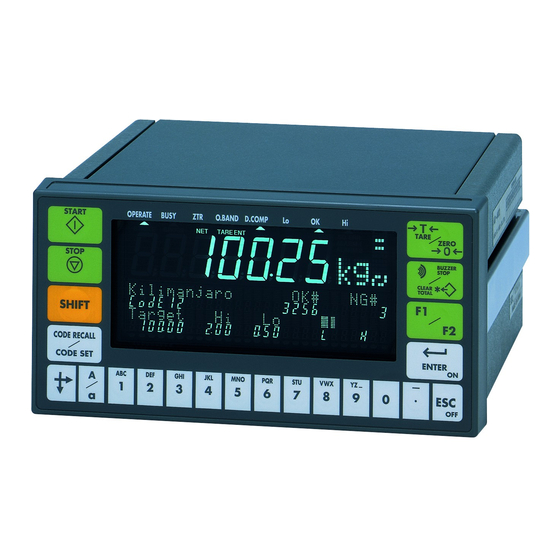
2.2. Front Panel 2.2. Front Panel 2.2. 2.2. Front Panel Front Panel Status indicator Main display Weighing data is displayed. Graphic status indicator Weighing unit Alphanumerical keys and Standby indicator numerical keys Sub-display Selected principal data. Example: Total data, parameters and code, guidance are displayed Display Status indicator... -
Page 11: Keys
2.2.1. 2.2.1. Keys Keys 2.2.1. 2.2.1. Keys Keys The START key of the conveyor belt. The STOP key of the conveyor belt. The key to select a function of a key. The key to call the code. Pressing the CODE RECALL key to recall the code. Pressing and holding the SHIFT key, press the CODE SET key to select the principal codes for display in the sub-display. -
Page 12: Symbols
2.2.2. 2.2.2. Symbols Symbols 2.2.2. 2.2.2. Symbols Symbols While weighing sequence mode stops, weighing data is displayed. Main display While weighing sequence mode operates, each judged weighing value is held and is displayed. Code numbers, operation guidance, graph, setpoint and others are Sub display displayed selectively. -
Page 13: Rear Panel
The weighing data is lighter than lower limit. Data < Lower limit. The weighing data is acceptable. Lower limit Data Higher limit The weighing data is heavier than higher limit. Higher limit Data 2.3. Rear Panel 2.3. Rear Panel 2.3. 2.3. -
Page 14: Installation
3. 3. 3. 3. Installation Installation Installation Installation Installation Procedure Remove the power cord before installing the indicator or an option. Turn off peripheral devices before connecting them. Insert the options before installing the indicator. Mount the indicator to the panel. Connect cables and wires to the indicator. -
Page 15: Mounting The Indicator
3.2. Mounting the Indicator 3.2. Mounting the Indicator 3.2. 3.2. Mounting the Indicator Mounting the Indicator The indicator can be mounted on a panel using the slide rails. If the accessory packing rubber is used, the front panel is equivalent to IP-65 of IEC 529. Panel M4x15 truss head screw M4 nylon washer... -
Page 16: Connecting The Loadcell Cable
3.3. Connecting the Loadcell Cable 3.3. Connecting the Loadcell Cable 3.3. 3.3. Connecting the Loadcell Cable Connecting the Loadcell Cable Caution Do not share the loadcell cable with noise-generating devices or power lines, because the loadcell signal is very sensitive. We recommend that you use a 6 wire shielded cable to prevent loss of weighing precision. -
Page 17: Verifying Loadcell Output And Input Sensitivity
3.3.1. 3.3.1. Verifying Verifying Loadcell Output and Input Sensitivity Loadcell Output and Input Sensitivity 3.3.1. 3.3.1. Verifying Verifying Loadcell Output and Input Sensitivity Loadcell Output and Input Sensitivity The input sensitivity of the indicator is 0.3 V/division or more. Adapt to the following inequality, when you design a weighing instrument using the indicator and loadcell(s). -
Page 18: Wiring The Power Cord
3.4. Wiring the Power Cord 3.4. Wiring the Power Cord 3.4. 3.4. Wiring the Power Cord Wiring the Power Cord Caution Ground the indicator using terminal E to avoid receiving an electric shock or an error due to discharge of static electricity. Do not share the ground wire with an electrical device that generates noise. -
Page 19: Basic Operation
4. 4. 4. 4. Basic Operation Basic Operation Basic Operation Basic Operation 4.1. 4.1. Key Operation Examples 4.1. 4.1. Key Operation Examples Key Operation Examples Key Operation Examples This section describes how to use key operation. Caution The key operation immediately affects to the status of the indicator. Always check the keys to select before proceeding. -
Page 20: Calling A Code
4.1.4. 4.1.4. Calling a Code Calling a Code 4.1.4. 4.1.4. Calling a Code Calling a Code Step 1 Press the CODE RECALL key in either operation mode or normal stop mode. Step 2 Set the code number with the following keys: key is used to increase the code number. -
Page 21: Status Chart
4.2. Status Chart 4.2. Status Chart 4.2. 4.2. Status Chart Status Chart 4.2.1. 4.2.1. 4.2.1. 4.2.1. Mode Map and Menu Mode Map and Menu Mode Map and Menu Mode Map and Menu Page 19... -
Page 22: Status Of Weighing Mode
4.2.2. 4.2.2. Status of Weighing Mode Status of Weighing Mode 4.2.2. 4.2.2. Status of Weighing Mode Status of Weighing Mode Weighing mode comprises of the following modes. Operation mode includes the following check weighing (weighing sequence). Automatic mode Conveyor stop mode OK mode Manual mode Simple mode... -
Page 23: Calibration
5. 5. 5. 5. Calibration Calibration Calibration Calibration The indicator, which is connected to a loadcell unit, can weigh the "weight" value on the weighing conveyor and display its "mass" value. The calibration function is used to adjust the displayed value so that the weighing system can weigh correctly. There are two ways of calibration. -
Page 24: Actual Load Calibration (Using A Mass)
5.1. Actual Load Calibration (using 5.1. Actual Load Calibration (using a a a a Mass) Mass) 5.1. 5.1. Actual Load Calibration (using Actual Load Calibration (using Mass) Mass) ESC key If you want to return to the weighing mode during the calibration mode, press the ESC key anytime. -
Page 25: Digital Span (Calibration Without A Mass)
5.2. Digital Span (Calibration without 5.2. Digital Span (Calibration without a a a a Mass) Mass) 5.2. 5.2. Digital Span (Calibration without Digital Span (Calibration without Mass) Mass) ESC key If you want to return to the normal stop mode during the calibration mode, press the ESC key anytime. -
Page 26: Gravity Acceleration Correction
5.3. Gravity Acceleration Correction 5.3. Gravity Acceleration Correction 5.3. 5.3. Gravity Acceleration Correction Gravity Acceleration Correction The function compensates for weighing error due to the difference of gravity acceleration. The place where the weighing system is calibrated. The place where the weighing system is used. ESC key If you want to return to the normal stop mode during the calibration mode, press the ESC key anytime. -
Page 27: Calibration Error
5.4. Calib 5.4. Calibration Error ration Error 5.4. 5.4. Calib Calib ration Error ration Error Error Code Error Status and Solution CERR1 Resolution (Weighing capacity / minimum division) exceeds the limitation. Increase minimum division or decrease weighing capacity. CERR2 The initial load (no load output) is larger than 2mV/V. Check the weighing conveyor, loadcell unit and cable. - Page 28 [Blank page] Page 26...
-
Page 29: Check Weighing Sequence
6. 6. 6. 6. Check Weighing Sequence Check Weighing Sequence Check Weighing Sequence Check Weighing Sequence 6.1. 6.1. Automatic 6.1. 6.1. Automatic Automatic Automatic Mode Mode Mode Mode ( weighing in motion) ( weighing in motion) ( weighing in motion) ( weighing in motion) The mode weighs and classifies (judges or checks) the weight of an article, when it passes it on the weighing conveyor. - Page 30 Gross Zero band Hi (Upper limit) Target Lo (Lower limit) Zero band, Output Main display Comparison display Setpoint, Input Start operation, Input Stop operation, Input OPERATE, Output Conveyor, Output Position sensor 5q f-42 Chattering timer 5q f-43 Judgement Judgement Judgement Eval delay timer 5q f-44 Front edge...
-
Page 31: Conveyor Stop Mode
6.2. Conveyor Stop Mode 6.2. Conveyor Stop Mode 6.2. 6.2. Conveyor Stop Mode Conveyor Stop Mode The conveyor stop mode is the function that the article is stopped on the weighing conveyor for accurate measurement. When the gross value is within zero band, the weighing value is not judged. The mode can be used with foreign matter detection. - Page 32 Gross Zero band Hi (Upper limit) Target Lo (Lower limit) Zero band, Output Main display Comparison display Setpoint, Input Start operation, Input Conveyor is stopped. Stop operation, Input OPERATE, Output Conveyor, Output Position sensor 5q f-42 Chattering timer 5q f-43 Judgement Judgement Judgement...
-
Page 33: Foreign Matter Detection
6.3. Foreign Matter Detection 6.3. Foreign Matter Detection 6.3. 6.3. Foreign Matter Detection Foreign Matter Detection The foreign matter detection is the function to reject an article including foreign matter. The system consists of the AD-4404 and the foreign matter detector. The rejection is performed with the following procedure. - Page 34 Gross Zero band Hi (Upper limit) Target Lo (Lower limit) Zero band, Output Main display Comparison display Setpoint, Input Start operation, Input Stop operation, Input OPERATE, Output Conveyor, Output Position sensor 5q f-42 Chattering timer 5q f-43 Judgement Judgement Judgement Eval delay timer 5q f-44 Front edge...
-
Page 35: Ok Mode
6.4. OK Mode 6.4. OK Mode 6.4. 6.4. OK Mode OK Mode The procedure of OK mode is as follows: 1 Put the article on the stopped weighing conveyor. 2 Pack the elements into the article by hand. 3 Press the START key. When the weighing value is OK, the article can be moved out. The mode can be used with the buzzer according to the preset parameters. - Page 36 Gross Zero band Hi (Upper limit) Target Lo (Lower limit) Zero band, Output Main display Comparison display Setpoint, Input Start operation, Input Stop operation, Input OPERATE, Output Conveyor, Output 5q f-59 Conveyor stop delay timer Position sensor 5q f-42 Chattering timer 5q f-43 Judgement Tail detection...
-
Page 37: Manual Mode
6.5. Manual Mode 6.5. Manual Mode 6.5. 6.5. Manual Mode Manual Mode The manual mode is the mode that weighs the article by hand operation and does not use a conveyor. In the stop mode, the current weighing value and comparison display are always updated. The comparison output and buzzer are turned off. - Page 38 Gross Zero band Hi (Upper limit) Target Lo (Lower limit) Zero band, Output Stability, Output Main display Comparison display Setpoint, Input Start operation, Input Stop operation, Input OPERATE, Output 5q f-43 Judgement Judgement Eval delay timer 5q f-44 Average timer Hi, Output OK, Output Lo, Output...
-
Page 39: Simple Mode
6.6. Simple Mode 6.6. Simple Mode 6.6. 6.6. Simple Mode Simple Mode The simple mode is used to compare the weighing value and the setpoints. Setpoints, means preset value to be used comparison, are used for buzzer, comparison display and output. There are five setpoints of LoLo, Lo, OK, Hi, HiHi. The current weighing value and the comparison display are always updated. - Page 40 Gross Zero band Hi (Upper limit) Target Lo (Lower limit) Zero band, Output Stability, Output Main display Comparison display Setpoint, Input Start operation, Input Stop operation, Input OPERATE, Output 5q f-43 Judgement Eval delay timer 5q f-44 Average timer Hi, Output OK, Output Lo, Output BUSY, Output...
-
Page 41: Status And Check Weighing Sequence
6.7. Status and Check Weighing 6.7. Status and Check Weighing Sequence Sequence 6.7. 6.7. Status and Check Weighing Status and Check Weighing Sequence Sequence The status of the indicator, the display and each interface are according to the status of the check weighing sequence. Preset a parameter for each terminal function in the menu ControlI/O. - Page 42 Location and function name....Status indicator 0.BAND (Zero band) In normal stop mode, operation It displays judgement whether the weighing value is mode, pause....... within zero band. Location and function name....Status indicator D.COMP (Dynamic compensation) In normal stop mode ......It turns off.
- Page 43 Location and function name....Graph indicator of sub-display In normal stop mode ......Graph of net is displayed. In operation mode For automatic mode, conveyor stop mode ........It displays and holds graph of result For manual mode, OK mode.... It turns off before judgement.
- Page 44 Location and function name....Selector output (HiHi, Hi, OK, Lo, LoLo) In normal stop mode ......It turns off. In operation mode For automatic mode, conveyor stop mode ........It is according to the following parameters. 5q f-46 Selection out 1 delay timer ] to 5q f-51 Selection out 6 delay timer...
-
Page 45: Code
7. 7. 7. 7. Code Code Code Code The code is necessary to weigh the article and is commonly used in all modes. The AD-4404 can store 100 set of codes without any power supply. When recalling a code in this mode, the code can be used. There are two ways to operate the code. -
Page 46: Use Of The Code
7.1. Use of the Code 7.1. Use of the Code 7.1. 7.1. Use of the Code Use of the Code 7.1.1. 7.1.1. 7.1.1. 7.1.1. Recalling a Code Recalling a Code Recalling a Code Recalling a Code A preset code can be recalled to use it always. Caution If the code number is changed during operation, the I/O status is changed, too. -
Page 47: The Menu Of Code Edit
7.2. The Menu of Code Edit 7.2. The Menu of Code Edit 7.2. 7.2. The Menu of Code Edit The Menu of Code Edit Code Edit The code can operate with the following menu of Edit ........Edits full parameters of the code. Search ......Finds a blank code. -
Page 48: Delete
7.2.3. 7.2.3. Delete Delete 7.2.3. 7.2.3. Delete Delete This menu item can delete all or a part of the data for the code. Step 1 Press and hold the ENTER key and press the key to enter the menu. Code Edit Step 2 Select using the key. -
Page 49: Preset Tare
7.2.5. 7.2.5. Preset Preset Tare Tare 7.2.5. 7.2.5. Preset Preset Tare Tare This menu item can store the current tare value to preset tare ( ) of the specified code. genff-12 Preset tare=0 choose Preset the genf-12 Preset tare=0 choose Last tare .. -
Page 50: Recalling A Code
7.3. Recalling a Code 7.3. Recalling a Code 7.3. 7.3. Recalling a Code Recalling a Code 5qf-81 Code recall method The method to recall a code can be selected at Function and parameter 5qf-81 Code recall method Key/Serial I/F 5qf-81 Code recall method Parallel I/F 5qf-81... - Page 51 Caution Parallel I/F When selecting ], do not specify the same function to the control I/O and OP-05. Example: External switch control External switch When selecting ], select 1nf-01 control ] [48] to terminal 1. External switch control External switch When selecting ], select 05f-01...
-
Page 52: Other Functions
8. 8. 8. 8. Other Functions Other Functions Other Functions Other Functions 8.1. 8.1. Zero Tracking Function 8.1. 8.1. Zero Tracking Function Zero Tracking Function Zero Tracking Function The function automatically traces the weighing deviation at the center of zero and keeps the zero display of the gross display. -
Page 53: Dynamic Zero Tracking Function
8.1.2. 8.1.2. Dynamic Dynamic Zero Tracking Function Zero Tracking Function 8.1.2. 8.1.2. Dynamic Dynamic Zero Tracking Function Zero Tracking Function The function is used during automatic mode and conveyor stop mode, also when the conveyor is moving. The function can be used for gross display. To average the weighing value is performed at a constant time before loading the article. -
Page 54: Judgement And Selector Action
8.2. Judgement and Selector Action 8.2. Judgement and Selector Action 8.2. 8.2. Judgement and Selector Action Judgement and Selector Action The function is used to weigh and classify (judge or check) the article put on the weighing 5q f-1 5q f-1 automatic mode conveyor stop mode conveyor in... -
Page 55: Loss-In-Weight
8.3. Loss 8.3. Loss- - - - in in in in- - - - weight weight 8.3. 8.3. Loss Loss weight weight The function is used to weigh the decrease of the articles in a positive value. 5q f-3 Loss-in-weight The tare value can be set from the following value. -
Page 56: Detection Method
8.5. Detection Method 8.5. Detection Method 8.5. 8.5. Detection Method Detection Method There are four detection methods for the article. Detecting the front of the article with the position sensor. Detecting the end of the article with the position sensor. Detecting gross above the zero band. -
Page 57: Detecting Gross Value Above Zero Band
8.5.3. 8.5.3. Detecting Gross Value above Zero Band Detecting Gross Value above Zero Band 8.5.3. 8.5.3. Detecting Gross Value above Zero Band Detecting Gross Value above Zero Band 5q f-29 Over zero band of gross Detector Select of the Procedure: 1 The article is moved on the weighing conveyor. -
Page 58: Duplication Of The Articles
8.7. Duplication of the Articles 8.7. Duplication of the Articles 8.7. 8.7. Duplication of the Articles Duplication of the Articles When the next article is placed on the weighing conveyor before the last article is SQ.ERR2 forwarded from the conveyor, an error message and is displayed and duplication is output. -
Page 59: Busy Output
8.9. BUSY Output 8.9. BUSY Output 8.9. 8.9. BUSY Output BUSY Output The BUSY output is turned on at loading the article on the weighing conveyor. The BUSY output is turned off until it classifies with the selector. And the AD-4404 can control up to ten articles continuously. If an article is loaded on the weighing conveyor after the busy state is off, it can avoid duplication and crush of the articles. -
Page 60: Output For Foreign Matter Detection
8.11. Output for Foreign Matter Detection 8.11. Output for Foreign Matter Detection 8.11. 8.11. Output for Foreign Matter Detection Output for Foreign Matter Detection Procedure: 1 When the sensor detects foreign matter and sends the signal to the AD-4404, the foreign matter detection is output until the AD-4404 judges the signal and totals it. -
Page 61: Output To Selectors
8.12.2. 8.12.2. Output to Selectors Output to Selectors 8.12.2. 8.12.2. Output to Selectors Output to Selectors The output is used to control the selector using the timer. A maximum of six selectors can be connected to the AD-4404. Output according to conditions and timers. 5q f-22 Selector 1 condition 5q f-23... -
Page 62: Buzzer Output
8.13. Buzzer 8.13. Buzzer Output Output 8.13. 8.13. Buzzer Buzzer Output Output The judgement of the buzzer output is the same as the judgement of comparison output. The buzzer can be select six rhythms of sound. Each buzzer condition stores conditions to sound it for LoLo, Lo, OK, Hi, HiHi, foreign matter, duplication, crush and counter limit. -
Page 63: Safety Check Function
8.15. Safety Check Function 8.15. Safety Check Function 8.15. 8.15. Safety Check Function Safety Check Function The safety check function stops the check weighing sequence, when an error occurs. The input of a safety check function can be assigned to a terminal of the control I/O or OP-05. -
Page 64: Zero Operation
8.16. Zero Operation 8.16. Zero Operation 8.16. 8.16. Zero Operation Zero Operation The zero operation zeroes the display and changes to the gross display. The operation can be performed from the front panel key or the input terminal of the control I/O. -
Page 65: Tare Operation
8.17. Tare Operation 8.17. Tare Operation 8.17. 8.17. Tare Operation Tare Operation The relation of the display is as follows: Net = Gross - Tare Key Operation Press the TARE key. Operation from Control I/O 1n f-xx ....The input terminal of the control I/O. Tare ........When it turns on, zero of net is displayed. -
Page 66: Preset Tare
8.18. Preset Tare 8.18. Preset Tare 8.18. 8.18. Preset Tare Preset Tare A preset tare (PT) can be stored in each code. The preset tare can be used, when the tare value is specified in advance. The relation of the display is as follows Net = Gross - PT Key Operation Store a preset value to PT of the code. -
Page 67: Customizing Sub Display
8.20. Customizing Sub Display 8.20. Customizing Sub Display 8.20. 8.20. Customizing Sub Display Customizing Sub Display Use the default sub-display pattern, if you want to reset it. The default uses 3 levels with a target. Select a format of the sub display. 5ub f-1 Basic display Use the default display of the sub display at... - Page 68 Items to append to the sub-display Column Item Name and Description Figures size size Not displayed Code name Target HiHi LoLo Zero band Count of target data Tare Target Count Count of total data Count of OK data Count of NG (without OK data) Count of Hi data 0 to 3 0 to26...
- Page 69 Example of Basic Display Layout Store items according to the arrow in order. The order is from upper-left side item to the right item and lower-left item to the right in order. 0 1 2 3 4 5 6 7 8 9 10 11 12 13 14 15 16 17 18 19 20 21 22 23 24 25 26 Object-01 Object-01 Target...
-
Page 70: Graph Display
8.21. Graph Display 8.21. Graph Display 8.21. 8.21. Graph Display Graph Display The graph indicates the current weighing value in the sub-display. HiHi indicator. Hi indicator. OK indicator. Level is displayed between Lo and Hi. Lo indicator. LoLo indicator.. 5q f-2 Selection comparison The indicator is controlled by Description... -
Page 71: Canceling Last Judgement
8.22. Canceling Last 8.22. Canceling Last Judgement Judgement 8.22. 8.22. Canceling Last Canceling Last Judgement Judgement The function can be operated with the terminal for the control I/O, when the terminal is Cancel the last result specified to The last judgement is canceled, when the terminal is active after the judgement. 8.23. -
Page 72: Error Message And Alarm
8.24. Error Message and Alarm 8.24. Error Message and Alarm 8.24. 8.24. Error Message and Alarm Error Message and Alarm When the indicator detects an error in the weighing system, an error message is displayed, alarm sounds and the error status is output to the control I/O. Press the ESC key to clear the message. - Page 73 Kind Description When the displayed value can not be set to zero with re-zero or tare, this message is displayed. Zero error Display can not be zeroed by zero compensation. ZR.ERR Display can not be zeroed by tare operation. Unstable display. When the weighing value is out of range and emergency stop is performed, this symbol is displayed.
-
Page 74: Graphic Status Indicator
8.25. Graphic Status Indicator 8.25. Graphic Status Indicator 8.25. 8.25. Graphic Status Indicator Graphic Status Indicator The indicator can display the weighing status and the result on the graphic status indicator. Graphic status indicator Upper Description Side LoLo The current result is LoLo. The current result is Lo. -
Page 75: Memory Backup
8.26. Memory Backup 8.26. Memory Backup 8.26. 8.26. Memory Backup Memory Backup The indicator has two kinds of memory. Flash memory This memory is used to store important data without power supplied that the occurrence of re-writing them is seldom. Life of re-writing them is approximately 100,000 times or more. -
Page 76: Interface
9. 9. 9. 9. Int Interface erface erface erface 9.1. 9.1. Control I/O Function 9.1. 9.1. Control I/O Function Control I/O Function Control I/O Function The control I/O is the interface to communicate system status and sequence commands between the indicator and peripherals. Input terminals ....11 lines that can be selected by the function Output terminals ....11 lines that can be selected by the function The output terminals use open collector transistors... -
Page 77: Timing Chart
9.1.2. 9.1.2. Timing Chart Timing Chart 9.1.2. 9.1.2. Timing Chart Timing Chart Caution Keep the delay time to avoid abnormal-operation and noise. Keep the input signal more than 50 ms to avoid noise and chattering. Acknowledge terminal is active for five seconds, when the indicator receives a signal. Example Turn off 50 ms or more. -
Page 78: Built-In Rs-485 Interface
9.2. Built 9.2. Built- - - - in RS in RS- - - - 485 Interface 485 Interface 9.2. 9.2. Built Built in RS in RS 485 Interface 485 Interface The RS-485 interface can use commands to control the indicator. The interface can read weighing data or parameters and store parameters in the indicator. -
Page 79: Connection
9.2.2. 9.2.2. Connection Connection 9.2.2. 9.2.2. Connection Connection AD-4404 Inside RS-485 RE/DE C.LOOP Shield Terminals Interface Circuit The host computer may have inverse polarity terminals. The host computer may include Terminator resistor 100 ~ 120 1/2W the terminator resistor. Host computer Unit 1 AD-4404 Use twisted-pair wire. -
Page 80: Timing Chart
9.2.3. 9.2.3. Timing Chart Timing Chart 9.2.3. 9.2.3. Timing Chart Timing Chart Keep the delay time above 0.5 ms between the last response and the next command. [r5 f- 9] < tr < [r5 f- 9] + 50 ms Set response time (tr). Use a long delay time, when there is noise. -
Page 81: General Data Format
9.2.5. 9.2.5. General Data Format General Data Format 9.2.5. 9.2.5. General Data Format General Data Format This format is used for the command mode and jet stream mode. 10 11 14 15 21 22 24 25 R G R S 0 0 9 9 1 2 3 4 5 6 7 1 2 3 4 5 6 7 8 9... -
Page 82: A&D Data Format
9.2.6. 9.2.6. A&D Data Format A&D Data Format 9.2.6. 9.2.6. A&D Data Format A&D Data Format This format is used for stream mode, auto print mode and total print. This format is compatible with the AD-4325 indicator. Header 1 Unit Header 2 Weighing data Terminator... -
Page 83: Address
9.2.7. 9.2.7. Address Address 9.2.7. 9.2.7. Address Address [r5 f- 8]. The address can be entered as a number Address Set the address at between 1 and 99. 32 units can be connected to a computer. Use multiple drop connection. [r5 f- 8] is always appended to the data in all modes of Address Communication... -
Page 84: Command List
9.2.8. 9.2.8. Command List Command List 9.2.8. 9.2.8. Command List Command List Monitor Commands Name Code Description r5 f-1 Output data Read displayed value RDSP Data specified at Read gross value RGRS Read net value RNET Read tare value RTAR Read weighing result RFIN Read setpoint... -
Page 85: Ascii Code For Display Characters
Response Error Code Response Description Note The format of command is not correct. When an address is used, The data of command is not correct. the address is appended to the response. Indicator is busy. 9.2.9. 9.2.9. 9.2.9. 9.2.9. ASCII Code for ASCII Code for ASCII Code for ASCII Code for Display... -
Page 86: Protocol (Communication Procedure And Format)
9.2.10. 9.2.10. Protocol Protocol (Communication Procedure (Communication Procedure and Format and Format) ) ) ) 9.2.10. 9.2.10. Protocol Protocol (Communication Procedure (Communication Procedure and Format and Format Caution When using the flash memory ( othf othf othf othf- - - - 11 11 = 2 2 2 2 , "Store in flash memory") and storing new code data with "Write Commands", new code data is not stored in the flash memory and the code data stored in the flash memory has... -
Page 87: Code Name
Command Protocol 64 characters. This command outputs setpoints of a selected code. Parameters are 7 figures with "-" sign at MSB when negative value and without decimal point. If code number is replaced with space codes (20h), the current setpoints are output. RSPT Computer RSPT0034... - Page 88 Command Protocol 138 characters. This command outputs total data of a selected code. Parameters are 7 figures with "-" sign at MSB when negative value and without decimal point. If code number is replaced with space codes (20h), the current total data of code are output. Computer RTTL0034 RTTL0034,1234567,...,123456789...
- Page 89 Write Commands Command Protocol 64 characters. This command stores setpoints of a selected code. Parameters are 7 figures with "-" sign at MSB when negative value and without decimal point. WSPT Computer WSPT0034,1234567,1234567,1234567,1234567,1234567, Store setpoints AD-4404 Store comparison parameters Code number, Target, Hi, Lo, HiHi, LoLo, Zero Band, Full, Code number 1234567,1234567 WSPT0034...
- Page 90 Command Protocol 226 characters. This command outputs all data of a selected code. Parameters are 7 figures with "-" sign at MSB when negative value and without decimal point. If code number is replaced with space codes (20h), the current code is output. Code number Computer RCOD0034...
- Page 91 Control Commands Command Protocol Re-zero command. CZER Computer CZER Make zero display CZER AD-4404 Tare command. CTAR Computer CTAR Tare CTAR AD-4404 To clear the tare command. CCTR Computer CCTR Tare clear CCTR AD-4404 To display the current gross value. CGRS Computer CGRS...
- Page 92 Command Protocol Computer CRER CRER CRER Reset an error AD-4404 Computer CNOP CNOP CNOP No operation AD-4404 Page 90...
-
Page 93: Modbus Interface For Rs-485
9.3. Modbus Interface for RS 9.3. Modbus Interface for RS- - - - 485 9.3. 9.3. Modbus Interface for RS Modbus Interface for RS Modbus is a kind of connection that is used with the RS-485 serial interface. It is not necessary to make a program for communication between these units. The communication uses the following memories of the monitor unit or computer. - Page 94 Coil ( Reference No.=0. Output bits Address Description Address Description Zero Cancel last result (Internal reservation) Print total Tare Forced finish Tare clear Error reset Operate Manual print Stop Net / Gross Stop buzzer Clear all total Input Status ( Reference No.=1.
- Page 95 Intput Status Reference No.=1 Intput Status Reference No.=1 Address Description Address Description 14641 to 14643 Total status of code 57 3377 to 3379 Total status of code 13 14897 to 14899 Total status of code 58 3633 to 3635 Total status of code 14 15153 to 15155 Total status of code 59 3889 to 3891 Total status of code 15...
-
Page 96: Count Of Foreign Matter
Intput Register ( Reference No.=3. To read words A word, occupies an address, is length of 16 bits. A code has these items in a total data. Example for code 0 is as follows: Total data of the code 0 Total data of the code 0 Address Description Address Description... - Page 97 Intput Register (Reference No.=3) Intput Register (Reference No.=3) To read data To read data Address Description Address Description 10529 to 10559 Total data of the code 41 18209 to 18239 Total data of the code 71 10785 to 10815 Total data of the code 42 18465 to 18495 Total data of the code 72 11041 to 11071 Total data of the code 43 18721 to 18751 Total data of the code 73...
- Page 98 Holding Register ( Reference No.=4. To write words A word, occupies an address, is 16 bits in length. A code has these items in a comparison data. Example for code 0 is as follows: Comparison data of the code 0 Comparison data of the code 0 Address Description Address Description...
- Page 99 Holding Register (Reference No.=4) Holding Register (Reference No.=4) To write comparison data To write comparison data Address Description Address Description 14337 to 14359 C.D. of the code 56 20225 to 20247 C.D. of the code 79 14593 to 14615 C.D. of the code 57 20481 to 20503 C.D.
-
Page 100: Built-In Current Loop Output
9.4. Built 9.4. Built- - - - in Current L in Current Loop Output oop Output 9.4. 9.4. Built Built in Current L in Current L oop Output oop Output The interface can be used to connect a printer or external monitor. Specifications Transmission system EIA RS-232C, Asynchronous, bi-directional, half-duplex... -
Page 101: Data Format
9.4.3. 9.4.3. Data Format Data Format 9.4.3. 9.4.3. Data Format Data Format The format is the same as A&D format of the built-in RS-485. 9.4.4. 9.4.4. 9.4.4. 9.4.4. Settings of Parameters for Current Loop Settings of Parameters for Current Loop Settings of Parameters for Current Loop Settings of Parameters for Current Loop Refer to the "11. - Page 102 Cl f- 2 Communication mode Auto print When the target count is up with auto print, data is printed automatically. [Function] - [Set function] - [Serial] - [C.loop] Cl f- 5 Parity check Select even or odd to adapt to the printer. [Function] - [Set function] - [Serial] - [C.loop] Mode 2 only Mode 4 only...
-
Page 103: Time Stamp
9.4.6. 9.4.6. Time Stamp Time Stamp 9.4.6. 9.4.6. Time Stamp Time Stamp If the printer has the function to print time and date, the time stamp can be appended to the printed data. Example: printer AD-8118A/B, AD-8121. The indicator can send the following commands. Date command ASCII code: 1B, 44 Time command... -
Page 104: Bcd Output Of Option Op-01
9.5. BCD Output of Opti 9.5. BCD Output of Option OP on OP- - - - 01 9.5. 9.5. BCD Output of Opti BCD Output of Opti on OP on OP The interface can be used to connect a printer or external monitor. Specifications Output circuit Open collector transistor... - Page 105 Terminals When weighing display [1], gross display [2], net display [3] or tare display [4] of [01f- 1] is output, the function of the terminals are as follows: Output mode Unit Unit 1 Unit 2 blank 0 1,000 2,000 4,000 8,000 10,000 80,000...
- Page 106 [01f- 1] [10] are output, the Output mode When alarm number and error number of function of the terminals are as follows: Sequence error 1 B1 Sequence error number number 4 B2 Error B3 Zero error 1 B5 Zero error number number 4 B6 Error B7...
- Page 107 Timing Chart When normal output [01f- 3] 4 is used 50 ms of delay time 50 ms of delay Approx. 20 ms of Approx. 10 ms from data to release it pulse width. time to hold it. input to strobe Data Output Strobe Hold input...
-
Page 108: Relay Output Of Option Op-02
9.6. Relay Output of Option OP 9.6. Relay Output of Option OP- - - - 02 9.6. 9.6. Relay Output of Option OP Relay Output of Option OP This option can output the same function as the control output to relays. Specifications Rated load 250 V AC, 3 A... -
Page 109: Rs-422/485 Interface Of Option Op-03
9.7. RS 9.7. RS- - - - 422/485 Interface of Option OP 422/485 Interface of Option OP- - - - 03 9.7. 9.7. 422/485 Interface of Option OP 422/485 Interface of Option OP The RS-422/485 interface can use commands to control the indicator. The interface can read weighing data or parameters or store parameters to the indicator. - Page 110 RS-422 Connections [03 f-11] [1] Settings RS-422 [03 f- 8] [0]. Address Number 0 Terminator resistor 100 ~ 120 1/2W Host computer SDA 1 SDB 2 RDA 3 RDB 4 The host computer may include SG 5 the terminator resistor. FG 6 TERMINATOR The host computer may have...
-
Page 111: Settings Of Parameters
RS-485 2 Wire Connections for Command Mode [03 f-11] [2] Settings RS-485 The host computer may include Terminator resistor the terminator resistor. 100 ~ 120 1/2W Host computer The host computer may have inverse polarity terminals. TERMINATOR AD-4402 No.1 2 (SDA) and 3 (SDB) connect nothing. -
Page 112: Rs-232C Interface Of Option Op-04
9.8. RS 9.8. RS- - - - 232C Interface of Option OP 232C Interface of Option OP- - - - 04 9.8. 9.8. 232C Interface of Option OP 232C Interface of Option OP The RS-232C is used to connect to the DEC (modem). The command and parameters of RS-232C is the same as the built-in RS-485. -
Page 113: Parallel I/O Of Option Op-05
9.9. Parallel I/O of Option OP 9.9. Parallel I/O of Option OP- - - - 05 9.9. 9.9. Parallel I/O of Option OP Parallel I/O of Option OP This option can be used to extend the terminals of the control I/O. The function, settings, interface circuit and timing chart of the option is the same as the control I/O. - Page 114 Circuit DC 7 ~ 11V Max. 5 mA It is recommend that you use : A1 to A 16 Mechanical switch or Input terminal open collector transistor. A17 to A19 Vsat < 2 V Common Input terminal AD-4404 OP-05 inside Max.
-
Page 115: Analog Output Of Option Op-07
9.10. Analog Output of Option OP 9.10. Analog Output of Option OP- - - - 07 9.10. 9.10. Analog Output of Option OP Analog Output of Option OP This option outputs DC current that is proportional to the display value. Factory adjusted to 4 mA output at zero display and 20 mA output at full scale. -
Page 116: Other Options
9.11. Other Options 9.11. Other Options 9.11. 9.11. Other Options Other Options Refer to the following instructions to use them. OP-20 CC-link interface OP-21 DeviceNet interface OP-22 PROFIBUS interface Page 114 AD-4404... -
Page 117: Maintenance (Monitor And Test)
10. Maintenance Maintenance Maintenance Maintenance (Monitor (Monitor and Test) and Test) (Monitor (Monitor and Test) and Test) 10.1.1. 10.1.1. Basic Operation Basic Operation 10.1.1. 10.1.1. Basic Operation Basic Operation To enter the maintenance function Press and hold the ENTER key and press the key in the weighing mode. -
Page 118: Monitoring Built-In Current Loop Output
10.2.3. 10.2.3. Monitoring Built Monitoring Built- - - - in Current L in Current Loop Output oop Output 10.2.3. 10.2.3. Monitoring Built Monitoring Built in Current L in Current L oop Output oop Output The current communication data is displayed. Output is according to Communication Cl f-02 mode [ : CR... -
Page 119: Monitoring Rs-422/485 Interface Of Op-03
10.2.7. 10.2.7. 10.2.7. 10.2.7. M M M M onitoring RS onitoring RS onitoring RS onitoring RS- - - - 422/485 Interface of OP 422/485 Interface of OP 422/485 Interface of OP- - - - 03 422/485 Interface of OP The current communication data is displayed. Output is according to Communication 03 f-02 mode [ : CR... -
Page 120: Test Mode
10.3. Test Mode 10.3. Test Mode 10.3. 10.3. Test Mode Test Mode The test mode is used to check the indicator and weighing system with a test signal. When the test mode is used, the weighing sequence is stopped. Caution Turn off the peripherals before test. -
Page 121: Testing A/D Converter
10.3.4. 10.3.4. Testing A/D Converter Testing A/D Converter 10.3.4. 10.3.4. Testing A/D Converter Testing A/D Converter The A/D converter data is displayed. When pressing the ENTER key, a test voltage can be input to the A/D converter. 16 . 0 01 A/D converter output Loadcell output A/D Count... -
Page 122: Testing Rs-232C Interface Of Op-04
10.3.8. 10.3.8. Testing RS Testing RS- - - - 232C Interface of OP 232C Interface of OP- - - - 04 10.3.8. 10.3.8. Testing RS Testing RS 232C Interface of OP 232C Interface of OP Each time to press the ENTER key, the test data "ST,GS,+0000000kg CR LF" is output. -
Page 123: Initializing Parameters
10.4. Initializing Parameters 10.4. Initializing Parameters 10.4. 10.4. Initializing Parameters Initializing Parameters This function initializes the parameters stored in the indicator. The parameters are stored in the flash memory and backup RAM. Caution There are reset functions that require re-calibration of the indicator Note where the parameters are stored. - Page 124 Procedure Caution Do not initialize parameters while in operation. Cut off the power supply of other systems. When initializing the indicator, the output may change. When initializing the indicator, do not turn off the indicator before it is reset. To enter initialization Step 1 Press and hold the ENTER key and press the key to display the menu in a weighing mode.
-
Page 125: Remote Operation
10.5. Remote Operation 10.5. Remote Operation 10.5. 10.5. Remote Operation Remote Operation This mode can read and write the parameters of the function list, the code data and calibration data. The built-in RS-485, RS-422/485 (OP-03) or RS-232C (OP-04) is used for remote operation. -
Page 126: Function List
11. Function List Function List Function List Function List The function list stores parameters to control the indicator. The parameters are stored in an item even without power supplied. An item is classified by a category address, and is further classified by an item number. -
Page 127: Outline Of The Function List
11.1.2. 11.1.2. Outline of the Function List Outline of the Function List 11.1.2. 11.1.2. Outline of the Function List Outline of the Function List Category Address Start Item Function Function reference General genf- 1 Weight 5ub f 1 Sub display othf- 1 Other Sequence... -
Page 128: Referring Parameters
11.2. Referring 11.2. Referring Parameters Parameters 11.2. 11.2. Referring Referring Parameters Parameters Use this mode to refer to the parameters in the weighing sequence. The temporary parameters can be input and used concerning the digital filter and weighing sequence timers in the weighing sequence. [genf- 2] Digital filtering [Function] - [Function setting] - [General] - [Weighing]... -
Page 129: Parameter List
11.3. Parameter List 11.3. Parameter List 11.3. 11.3. Parameter List Parameter List Category address: [Function] - [Set Function] - [General] - [Weighing] Category Range address Name Descriptions Default symbol choices 1: 5 times / second Display genf- 1 2: 10 times /second 1 to 3 refresh rate 3: 20 times / second... - Page 130 Category Range address Name Descriptions Default symbol choices 1: If tare value of code is zero, the last tare value is used. Preset tare=0 genf-12 1 to 2 2: If tare value of code is zero, tare is set choose to zero.
- Page 131 Category address: [Function] - [Set Function] - [General] - [Sub display] Category Range address Name Descriptions Default symbol choices Weighing 0: Basic format 5Ubf- 1 0 to 1 display 1: Custom format Refer to "8.20. Customizing the Sub Display" When custom format is used (When [5Ubf- 1] [1] ), set items to be displayed in the sub-display.
-
Page 132: Count Of Target Data
Items to append to the sub-display Column Item Name and Description Figures size size Not displayed Code name Target HiHi LoLo Zero band Count of target data Tare Target Count Count of total data Count of OK data Count of NG (without OK data) Count of Hi data 0 to 3 0 to26... -
Page 133: Target
Example of Basic Display Layout Store items according to the arrow in order. The order is from upper-left side item to the right item and lower-left item to the right in order. 0 1 2 3 4 5 6 7 8 9 10 11 12 13 14 15 16 17 18 19 20 21 22 23 24 25 26 Object-01 Object-01 Target... -
Page 134: Hihi
Category address: [Function] - [Set Function] - [General] - [Sub-display] Category Range address Name Descriptions Default symbol choices Graphic Status Indicator Activity 0: Hide 5Ubf- 2 0 to 1 indicator 1: Upper side 2: Lower side Graphic status indicator Upper Description Side LoLo... - Page 135 Category address: [Function] - [Set Function] - [General] - [Others] Category Range address Name Descriptions Default symbol choices Set the action of each key. Bit 1: F1 key Bit 2: F2 key Bit 3: Start Bit 4: Stop Bit 5: Code recall Bit 6: Code set 0000000 00000...
- Page 136 Category Range address Name Descriptions Default symbol choices The selection to print unstable data or data of out of range in the current loop output or RS-485 of serial interface. Printing when This item has no effect in command othf- 6 0 ot 1 unstable mode and jet stream mode.
- Page 137 Category address: [Function] - [Set Function] - [Sequence] - [Basic] Category Range address Name Descriptions Default symbol choices 1: Automatic mode 2: Conveyor stop mode 5q f- 1 Weighing mode 3: OK mode 1 to 5 4: Manual mode 5: Simple mode Setpoints and comparison method Refer to "8.2.
- Page 138 Category Range address Name Descriptions Default symbol choices Select 3dB band for two low pass digital filter. 0: Not used 1: 11 Hz 2: 8.0 Hz Difital 3: 5.6 Hz A/D converter 5q f-11 filter on 0 to 99 4: 4.0 Hz running 5: 2.8 Hz First filter...
- Page 139 Category address: [Function] - [Set Function] - [Sequence] - [Control] Category Range address Name Descriptions Default symbol choices Bit 1: LoLo Bit 2: Lo Bit 3: OK Bit 4: Hi Bit 5: HiHi 0000000 Conveyor stop Bit 6: Foreign matter detection 00 to 11011 5q f-21...
- Page 140 Category address: [Function] - [Set Function] - [Sequence] - [Timer] Category Range address Name Descriptions Default symbol choices Buzzer on The time to sound the buzzer. 0.00 to 5q f-41 1.00 s timer If it is 0, buzzer sounds until it is canceled. 99.99 s Chatering 0.00 to...
- Page 141 Category address: [Function] - [Set Function] - [Sequence] - [Zero track] Parameters for Dynamic Zero Tracking Function Category Range address Name Descriptions Default symbol choices Zero tracking The time to stop zero tacking before 0.0 to 5q f-71 1.0 s back timer weighing the article.
- Page 142 Category address: [Function] - [Set Function] - [Sequence] - [Other] Category Range address Name Descriptions Default symbol choices Refer to "7.3. The Method to Recall a Code" Code recall 5q f-81 1: Key/Serial I/F 1 to 3 method 2: Parallel I/F 3: External switch control When recalling the code, the function to hide preset item.
- Page 143 Category address: [Function] - [Set Function] - [Control I/O] - [Input] The list to assign the function for the input terminal of the control I/O Function Description Read Function Description Read No function Do not change. Internal reservation. Zero Edge (Internal reservation) Safety check input 1 Level...
- Page 144 Category address: [Function] - [Set Function] - [Control I/O] - [Output] The list to assign the function for the output terminal of the control I/O Function Description Function Description 0 No function 23 Alam 1 1 Stable 24 Alam 2 2 Zero band 25 Zero error 3 Full...
- Page 145 Definitions of word of Input Terminals for Control I/O Function Name Action and Description The detection of "Start input" and "Stop input" uses leading edge. Start The detection of "Emergency stop" uses signal level. Stop If "Emergency stop" is input, the conveyor is stopped, selectors Emergency stop turn off and all operation input is inhibited for safety.
- Page 146 Category address: [Function] - [Set Function] - [Serial] - [RS-485] Category Range address Name Descriptions Default symbol choices When jet stream mode of [r5 f- 2] is used, 1, 2 or 3 can be selected. When the display value is held in jet stream mode, output is not stopped.
- Page 147 Category Range address Name Descriptions Default symbol choices 0: Do not print total data 1: Total print mode 1 2: Total print mode 2 r5 f- 12 Process print 3: Total print mode 3 0 to 6 4: Total print mode 4 5: Total print mode 5 6: Total print mode 6 0: Do not print date and time...
- Page 148 Category address: [Function] - [Set Function] - [Serial] - [C.loop] Category Range address Name Descriptions Default symbol choices 1: Displayed value 2: Gross value 3: Net value 4: Tare value 5: Gross value/ Net value/ Tare value Cl f- 1 Output data 6: Displayed value with code 1 to 10...
- Page 149 Category address: [Function] - [Set Function] - [Option] - [slot n] - OP-01] OP-01: Option BCD Output slot n : slot number Category Range address Name Descriptions Default symbol choices 1: Displayed value 2: Gross value 3: Net value 4: Tare value 5: Current code total 01 f- 1 Out put data...
- Page 150 Category address: [Function] - [Set Function] - [Option] - [slot n] - [OP-02] OP-02: Option Relay Output slot n : slot number The functions of the relay output are the same as the functions of the output of the control I/O. Refer to the terminal functions of the output of the control I/O.
- Page 151 Category address: [Function] - [Set Function] - [Option] - [slot n] - [OP-03] or Category address: [Function] - [Set Function] - [Option] - [slot n] - [OP-04] slot n : slot number OP-04: Option RS-232C Interface OP-03: Option RS-422 / RS-485 Interface Category Range address...
- Page 152 Category Range address Name Descriptions Default symbol choices Response Set the waiting timer from receiving 0.00 to 03 f- 9 0.00 s timer command to transmitting a response. 2.55 s RS-422 / 485 1: RS-422 03 f-11 1 to 2 switch 2: RS-485 0: Do not print total data...
- Page 153 Category address: [Function] - [Set Function] - [Option] - [slot n] - [OP-05] OP-05: Option Parallel I/O slot n : slot number The functions of the parallel I/O are the same as the functions of the control I/O. Refer to the terminal functions of the control I/O. [Function] - [Set Function] - [Control I/O] Assign the function to the parallel I/O.
- Page 154 Output Terminals of OP-05 The functions of the parallel I/O are the same as the functions of the control I/O. Refer to the terminal functions of the control I/O. [Function] - [Set Function] - [Control I/O] Assign the function to the parallel I/O. Category Range address...
- Page 155 Category address: [Function] - [Set Function] - [Option] - [slot n] - [OP-07] OP-07: Option Analog Output slot n : slot number Refer to "9.10. Analog Output of Option OP-07" Category Range address Name Descriptions Default symbol choices 1: Displayed value 07 f- 1 Out put data 2: Gross value...
-
Page 156: Specifications
12. Specifications Specifications Specifications Specifications General Power supply 85 to 250 VAC, 50 or 60Hz, (Stable power source) Power consumption Approximately 30 VA Physical dimensions 192 (W) x 96 (H) x 135 (D) mm Weight Approximately 1.8 kg Panel cutout size 186 x 92 mm Operation temperature -5 °C to 40 °C... - Page 157 Weighing sequence mode Weighing mode Automatic Mode Conveyor Stop Mode OK Mode Manual Mode Simple Mode Code data Max. number of material codes 100 codes Elements of the material code Name, Target weight, Hi, Lo, HiHi, LoLo, Zero band, Full, Preset tare, Target count, Total count, OK count, NG count, Hi count, Lo count, HiHi count, LoLo count, Foreign matter detection count, Duplication count, Crush count, Maximum,...
- Page 158 Parallel I/O of Option OP-05 Refer to "9.9. Parallel I/O of Option OP-05". Analog Output of Option OP-07 Refer to "9.10. Analog Output of Option OP-07". CC Link interface of Option OP-20 Refer to OP-20 instruction manual regarding the details. DeviceNet interface of Option OP-21 Refer to OP-21 instruction manual regarding the details.
-
Page 159: Dimensions
12.1. Dimensions 12.1. Dimensions 12.1. 12.1. Dimensions Dimensions Panel cutout size 12.2. Access 12.2. Accessories ories 12.2. 12.2. Access Access ories ories Capacity label ............1 I/O connector ............1 JI-361J024-AG I/O connector cover ..........1 JI-360C024-B RS-485, terminator resistor 100 ...... -
Page 160: Index
13. Index Index Index Index CERR3 ........14, 25 [Control I/O] - [Input] ......141 CERR4 ..........25 [Control I/O] - [Output] ......142 CERR6 ..........25 [General] - [Others]......133 CERR7 ..........25 [General] - [Sub-display] ....129, 132 CERR8 .......... - Page 161 EMC ............. 5 SHIFT key ..... 9, 17, 18, 115 Emergency stop mode ....... 20 START key........9 Error code .......... 25 STOP key.......... 9 EXC- ..........14 Tare key ..........9 EXC+..........14 ZERO key.......... 9 FCC............5 Loadcell........11, 14, 15 Flash memory ........
- Page 162 Standby mode ........19 Total print mode ......... 78 Start bit......76, 98, 107, 110 Unit............. 21 Stop bits ....... 76, 98, 107, 110 VFD............6 Stop mode.......... 20 Water-resistant panel ......6 Stream mode......78, 98, 104 Weighing status ......... 72 Sub-display ........
Need help?
Do you have a question about the Check Weighing Indicator AD-4404 and is the answer not in the manual?
Questions and answers