
Related Manuals for AND AD-4430B


Summary of Contents for AND AD-4430B
- Page 1 4430B 4430B with BCD Output with BCD Output Rail Weighing Module Rail Weighing Module 1WMPD4002678C...
- Page 2 Under the copyright laws, the software (program) described in this manual is copyrighted, with all rights reserved. The software may be installed into one computer and may not be installed into other computers without the prior written consent of A&D Company, Limited.
-
Page 3: Table Of Contents
General ..........................8 3.3.4. Accessories ........................8 3.3.5. Dimensions ........................9 3.4. Names (The Front Panel And Rear Panel ) ............... 10 Installing The Module ........................ 11 4.1. Conditions To Install The Module ..................11 4.2. Power Supply ........................11 4.3. - Page 4 Displaying Function Parameters For The Calibration ( ) ....... 39 7.3. Initializing Parameters ......................40 7.3.1. Initializing Mode For RAM And Function Parameters ..........40 7.3.2. Initializing The Whole Data .................... 40 7.4. Verifying The Load Cell Connections ( DIAGNOS ) ............41 7.4.1.
- Page 5 Illustration 8 Gravity Acceleration Graph ....................... 23 Illustration 9 Digital linearization ........................23 Illustration 10 Load cell output adjustment ....................30 Illustration 11 Wire Name of Load Cell ......................41 Illustration 12 Connection Check of Load Cell ..................... 43 AD-4430B - 3 -...
-
Page 6: Compliance
Please note that this equipment generates, uses and can radiate radio frequency energy. This equipment has been tested and has been found to comply with the limits of a Class A computing device pursuant to Subpart J of Part 15 of FCC rules. These rules are designed to provide reasonable protection against interference when this equipment is operated in a commercial environment. - Page 7 The protective cover is for preventing wire chips when you will install and wire so please do not take off the cover until complete the installing and wiring. AD-4430B with a protective cover...
-
Page 8: Outline And Features
Outline and Features The AD-4430B has the following features. The AD-4430B is a weighing indicator that amplifies signals from a load cell, converts it to digital data and displays it as a mass value. This indicator has the following performance : Input sensitivity : ...... -
Page 9: Specifications
3.2. Display And Keys Measurement display 5 - digit 7-segment green LED Display element Status indicators 6 red LEDs Numerical display Switches between NET and GROSS Measurement Decimal point Selectable decimal places (10 , 10 , 10 , 10 display Overflow display All the digits turn OFF. -
Page 10: Weighing Function
Cutoff frequency (-3 dB) range : 0.7 to 100 Hz Zero detection Detects to place nothing on the weighing pan. Comparator Compares the measurement with these limits and outputs the results. Displays the measurement value held. Hold function Select from normal hold, peak hold, averaging hold. -
Page 11: Dimensions
3.3.5. Dimensions 35.3 (2.5) 20° 39.4 A&D Company, Limited 34.5 36.1 Unit : mm Illustration 1 Dimensions AD-4430B - 9 -... -
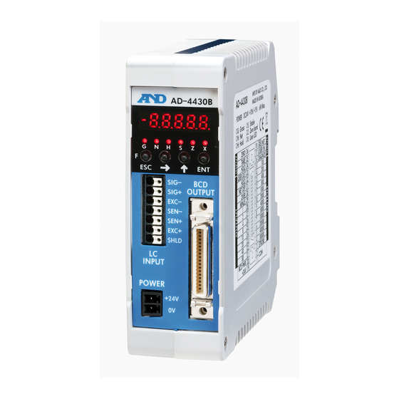
Page 12: Names (The Front Panel And Rear Panel )
3.4. Names (The Front Panel And Rear Panel ) Illustration 2 Front panel & rear panel Main display Status indicators Key switches Vent Sensor terminals of load cell Guide for DIN rail BCD connector Power supply connector Hook for DIN rail Pull down it when removing. -
Page 13: Installing The Module
Installing The Module This section is explained for the environment to install the module and for the terminals of the power source and load cell cable. Refer to each section of options for I/O interface. 4.1. Conditions To Install The Module The module is a precision electronic instrument. -
Page 14: Connecting Load Cell Cable
Load Cell Terminal Connections Two types of load cell connection are available: 6-wire connection and 4-wire connection. For high precision and stable weighing, 6-wire connection is recommended. Terminal No. -
Page 15: Verifying Load Cell Cable
If the 4-wire connection has to be used, please take the following measures. Be sure to connect terminals EXC+(6) and SEN+( 5 ) and terminals SEN-(4) and EXC-(3). When lengthening the load cell cable, try to use cable with a large cross-sectional area. -
Page 16: Operations
( Zero tracking width ) : The value between 0.0 and 9.9 d can be specified. (d = minimum division) 5.1.3. The Tare Function Tare is a function to store the gross weight as the tare value and set the net weight to zero. It is performed by pressing the key. (TARE) The tare weight is stored in the non-volatile memory and is maintained, even if the power is disconnected. -
Page 17: Clearing The Tare Value And Zero Operation
These switches work as follows : Alternate switch When pressing and releasing the switch once, the state of the switch is maintained. Press the switch again to turn off or on. Momentary switch Only while the switch is being pressed, the switch is ON. -
Page 18: Customizing The Function Of The X Display
(Comparison mass of upper and lower limit) : Gross weight or net weight to be compared with the upper or lower limit value can be selected. (Output logic of upper and lower limit) : Positive logic or negative logic to output the upper and lower limit can be selected. -
Page 19: 5.1.10. The Hold Function
The value will be refreshed if it increases again. Averaging hold This function averages weighing data over a certain period of time and then holds the result. It is useful for measuring things that are difficult to weigh such as an animal that won’t settle down, or for averaging out the weight of an object in an unstable state. -
Page 20: State Diagram And Operation Switches
5.2. State Diagram And Operation Switches 5.2.1. State Diagram The nonvolatile memory always stores either OFF mode or other mode. It starts from the following state depending on the mode that has been kept when the automatic power is on. -
Page 21: Operation Switches
5.2.2. Operation Switches State Function and Use The display toggles between gross and net in factory setting. Weighing mode The function key to select a function or use. Setting mode key. Weighing mode The zero key. Setting mode The key to change the selected item or move a flashing figure. -
Page 22: Calibration
( These value relate the input voltage of span and the weight value.) The correction calculates and corrects for gravity acceleration if the location Gravity acceleration where the module was calibrated and the location where it is being used in are correction different. -
Page 23: Calibrating With A Weight
The calibration weight value (the current weighing capacity) is displayed and the least digit of the value blinks. Correct the value using the key so as to be the value of the calibration weight Example used. If span calibration is not performed, press three times the key for returning to the weighing mode. -
Page 24: Gravity Acceleration Correction
(the place it was calibrated and the place it is being used in). Note When the span is calibrated with actual load calibration, the gravity acceleration correction settings are cleared, and the two gravity acceleration settings return to their default values. -
Page 25: Digital Linearization
It is possible to input up to four points in addition to the zero point. The zero point and each input point will be corrected to put them in a straight line. Areas between input points that could not be corrected completely with straight line correction or with secondary correction will be corrected using a curved line derived from high-order equations. -
Page 26: The Actual Load Linearization Function
If monitoring the current weighing value, press the key. When pressing the key again, is display. Step 3 Placed nothing on the pan and wait for the stabilization ( LED ). Press the key. is displayed for approximately two seconds. -
Page 27: The Calibration Function
The current data is displayed. Step 4 When changing data, two methods of parameter selection and digital input depending on the function are available. Type Description of method to change data Only the available parameter is displayed and blinks. - Page 28 Weighing is possible up to the value of this setting plus Weighing capacity 70000 8 d. If the value exceeds this, overflow will occur and 1 to 99999 will not be displayed. The decimal point position is the same as the setting of...
- Page 29 Weight value STABLE signal Time Tare and zero adjustment when the weight value is Tare and zero unstable. adjustment when 0 to 1 0 : Disables both functions.
- Page 30 , “zero calibration” and “span calibration” can be adjusted optionally. (Digital span accuracy approximately 1/5000. The accuracy varies depending on the load cell output accuracy and the conditions of calibration.) Except for an emergency, perform calibration with an actual load.
-
Page 31: The Linearization Function
Linear 1 The mass value for linear 1 input. 0 to 99999 Mass value The decimal point position depends on Linear 1 The span voltage between linear-zero and linear 1 0.0000 0.0000 Span voltage input. Unit : mV/V. to 9.9999 Linear 2 The mass value for linear 2 input. -
Page 32: Error Codes For The Calibration
Adjustment Of The Loadcell Output Add a resistor as shown below to adjust the load cell output. Use a resistor with a high resistance value and a low temperature coefficient. When exceeding in the positive direction. When exceeding in the negative direction. -
Page 33: General Functions
5.4. General Functions In this section, the way of pre-setting and descriptions for the general functions is described. General functions are divided into groups according to function and are indicated by the group name with the function number. NOTE: General functions determine the module performance and all of the settings are stored in the FRAM. -
Page 34: The Adjustment Of The Digital Filter
It is possible to make adjustments while watching the effects of the digital filter with your own eyes. By pressing the key while setting (digital filter), it is possible to check the weight displayed. Increase stability. Return to the value setting display. - 32 - AD-4430B... -
Page 35: The Basics Function
5 : HI output (Over the upper limit value) 0 to 9 6 : OK output (Between upper and lower limit values) 7 : LO output (Below the lower limit value) 8 : User input 1 9 : User output 1 Selects a cutoff frequency. -
Page 36: The Hold Function ( )
Lower limit Reference value for the lower limit. -99999 to 99999 value Decimal point position is linked to Item to be compared with the upper and lower limit. Comparison 1 : Gross weight mass of upper 1 to 2 2 : Net weight... -
Page 37: The Bcd Function
7 : LO output (Under lower limit) 8 : During operating weighing (On) 9 : During operating weighing (1 Hz) 10 : During operating weighing (50 Hz) 11 : Alarm (Zero correction error and tare error ) 12 : Busy AD-4430B - 35 -... -
Page 38: Interface
The Parallel BCD Output 6.1.1. Timing Chart Of The BCD Output The strobe signal becomes "1" when starting data transmission and becomes "2" after the strobe time. The strobe pulse band takes half the time to transmit data. Data output... -
Page 39: Positive Logic And Negative Logic
The output terminal is conductive in negative logic (A-Contact: Normally open) when the output signal is "1". The output circuits of the AD-4430B are an open collector as shown below. ex. The MINUS output terminal To light the load LED when the BCD output value is minus, select the negative logic in the "5.4.5. -
Page 40: Maintenance
The setting value is out of the Check the setting value and set again. settable range. 7.2. Check Mode The check mode checks the performance of the display, key switches and external I/O. 7.2.1. Entering The Check Mode Step 1 Press the... -
Page 41: Verifying The Switch Operation
The load cell output voltage rate is displayed in unit of mV/V . ex. If internal count is 1.2345 mV/V , If value is above ±7 mV/V, a damage and connection error of the load cell may cause . Refer to "7.5. Verifying The Load cell Connections Using Multimeter". -
Page 42: Initializing Parameters
Check that all status LED are blinking. If performing the initialization, press the key for 3 seconds or more. After initialization, all segments light and return to the weighing mode. If canceling the initialization, press the key return to the weighing mode. -
Page 43: Verifying The Load Cell Connections ( Diagnos )
Verifying The Load Cell Connections ( DIAGNOS ) 7.4.1. Guideline To Verify The Load Cell Connections The faulty wiring or disconnection of the load cell can be checked using the AD-4430B. This verification is useful for new setting, pre-measurement inspection and periodical inspection. Check Item... -
Page 44: Verifying Load Cell Connections With Switch Operation
Select self-check mode using the key. Press the key to enter self-check mode. The checks are performed for the selected items and results are displayed for approx. 16 seconds. Each measurement value can be displayed using the key. 7.4.4. Display and Output of Check Results... -
Page 45: Verifying The Load Cell Connections Using Multimeter
Approximately 2.5 V, about a half of excitation voltage. Generally, it is within 0 V to 15 mV. The theoretical SIG+ SIG- Output voltage value is calculated from the load cell rated capacity, actual load and excitation voltage. AD-4430B - 43 -... - Page 46 When the module does not operate properly, write the required items in the table below and contact your local A&D dealer. Usage circumstances, Item model number, rated, Note measurement value etc. When using the 4-wire connection, connect 4-wire connection Connection method...
-
Page 47: The Parameter List For The Function List
8 d. If Weighing 70000 1 to the value exceeds this, overflow will occur and capacity 99999 will not be displayed. The decimal point position is the same as the setting of... - Page 48 Input voltage from a load cell at span. Unit : mV/V. Input voltage 3.2000 0.0001 This value and the value of are determined in at span to 9.9999 span calibration during the calibration with an actual load. The input voltage at span for...
-
Page 49: The Linearization Function ( )
2 : Hold 3 : Alternate switch 0 to 7 function 4 : Momentary switch 5 : Changing between gross weight and net weight 6 : Clear the tare weight 7 : Clear the zero value AD-4430B - 47 -... - Page 50 5 : HI output (Over the upper limit value) 0 to 9 6 : OK output (Between upper and lower limit values) 7 : LO output (Below the lower limit value) 8 : User input 1 9 : User output 1 Selects a cutoff frequency.
-
Page 51: The Hold Function ( )
Condition to start the hold or averaging automatically. Condition of 0 : Do not use automatic start. automatic 0 to 2 1 : Above the near-zero range, and stable. start 2 : Above the near-zero range. Release when control input is falling. Release... - Page 52 7 : LO output (Under lower limit) 8 : During operating weighing (On) 9 : During operating weighing (1 Hz) 10 : During operating weighing (50 Hz) 11 : Alarm (Zero correction error and tare error ) 12 : Busy - 50 - AD-4430B...
- Page 53 MEMO AD-4430B - 51 -...
- Page 54 MEMO - 52 - AD-4430B...
- Page 56 3-23-14 Higashi-Ikebukuro, Toshima-ku, Tokyo 170-0013, JAPAN Telephone: [81] (3) 5391-6132 Fax: [81] (3) 5391-6148 A&D ENGINEERING, INC. 1756 Automation Parkway, San Jose, California 95131, U.S.A. Telephone: [1] (408) 263-5333 Fax: [1] (408)263-0119 A&D INSTRUMENTS LIMITED Unit 24/26 Blacklands Way, Abingdon Business Park, Abingdon, Oxfordshire OX14 1DY United Kingdom Telephone: [44] (1235) 550420 Fax: [44] (1235) 550485 A&D AUSTRALASIA PTY LTD...
Need help?
Do you have a question about the AD-4430B and is the answer not in the manual?
Questions and answers