Table of Contents
Advertisement
Quick Links
Advertisement
Table of Contents

Related Manuals for AND AD-4412-CW


Summary of Contents for AND AD-4412-CW
- Page 1 Weighing Indicator 1WMPD4003953A...
- Page 2 A&D Company, Limited. The contents of this manual and the specifications of the instrument covered by this manual are subject to change for improvement without notice.
-
Page 3: Table Of Contents
Settings of Threshold Values ( Target, HiHi Limit, Hi Limit, Lo Limit, LoLo Limit ) ..... 33 5.6.3. Setting Product Length and Velocity ..................34 5.6.4. Setting the Digital Output (DO) .................... 35 5.6.5. Setting the Delay Time and Holding Time ................36 AD-4412-CW, AD-4413-CW... - Page 4 Output of Weighing History ....................52 7.1.2. Example: Output File of Weighing History ................53 7.1.3. PDF output of Histogram, Control Chart and Summary ............ 54 7.2. Output to the Postscript Printer ....................55 7.2.1. Output to Postscript Printer ....................55 7.2.2.
- Page 5 Feedback Control Step : [g/sec.] or [sec./g] ................ 84 9.10.4. Feedback Control Sample ....................84 9.10.5. Feedback Control Waiting Time ................... 84 9.11. Step Control ..........................85 9.11.1. Control Target ........................85 9.11.2. Zone 1 to 4 of 10 Stage Control ................... 86 AD-4412-CW, AD-4413-CW...
- Page 6 9.18.1. Input Trigger .......................... 94 9.18.2. Configuration ......................... 96 9.18.3. Delay Time ..........................99 9.18.4. Chattering ..........................99 9.19. DI Indicator ..........................100 9.20. Analog Out ..........................101 9.20.1. Data Types .......................... 101 9.20.2. Output Format ........................101 AD-4412-CW, AD-4413-CW...
- Page 7 Serial Number ........................102 9.21.3. GUI Software Version ......................102 9.21.4. Weighing Software Version ....................102 9.21.5. Option Port 1 and 2 ......................102 9.22. Date / Time ..........................102 9.22.1. Date Set ..........................102 9.22.2. Time Set ..........................102 9.23.
- Page 8 Error Message Table......................152 12.2. Backup of System Data ......................153 12.3. Restoring System Data ......................154 12.4. Initialization to Factory Settings....................156 Specifications ..........................157 13.1. Dimensions ..........................158 13.1.1. AD-4412-CW ........................158 13.1.2. AD-4413-CW ........................159 AD-4412-CW, AD-4413-CW...
-
Page 9: Introduction
The indicator can store 1000 products (100 products for each 10 group) in maximum. The indicator can read picture from USB flash drive and display it on touch screen. User data can be stored, classified and managed properly using management level. -
Page 10: Safety Precautions
Caution Hazard of rotating object Keep hands and fingers away from the rotating part while the indicator is running. If product has stayed on conveyor, fell over or spilled, stop the indicator immediately, turn the power off and take necessary actions. -
Page 11: Compliance
Compliance Adaptation for local laws The indicator has been tested and complies with Subpart J of Part 15 of FCC rules. (FCC = Federal Communications Commission in the U.S.A.) The indicator equips a licensed wireless communication unit used 2.4 GHz band that specifies 2AC7Z-ESPWROOM02 to FCC ID. -
Page 12: Parts Names
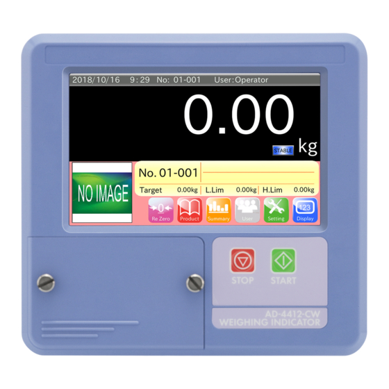
Table 1 Names and functions of front panel Name Description and Function 1. Touch screen The indication and settings of weighing can be displayed and operated. 2. Start button Weighing can start and conveyor can run. 3. Stop button Weighing and conveyor can stop. -
Page 13: Rear Panel
Input : 11 points. Output : 11 points. RS-485 and photo eye sensor terminals. 6. I/F terminals It is used for stream mode and communication with PLC using Modbus RTU. It uses as power source of photo eye sensor. 7. Power switch It is the main power supply switch for the indicator. -
Page 14: Installing The Weighing Indicator
The terminal are used when product image data is registered and output data is stored into USB flash drive. If you use USB flash drive, open the cover and connect USB flash drive to the USB terminal. When USB flash drive is identified by the indicator, USB mark is displayed at right-upper side of the screen. -
Page 15: Installing Option Board
Wait for 10 seconds and operate them. Caution Fix screws securely and do not leave loosen screw. If a loosen screw is left, electrical circuit may short during use. It may cause malfunction due to noise. Drawing 6 Installing option bard 3.3. -
Page 16: Panel Mount Kit ( Ad-4412-10 )
Step 2. Mount the indicator on the panel so as not to be kinked sealing gasket. Step 3. Slide attachment parts on trenches of both side. Fix the indicator using attachment parts and screws (two M4x12) to be able to protect from water. Step 4. Check the installation. -
Page 17: Attachment Kit ( Ad-4412-11 ) For Indicator Stand ( Ad-4402-25 )
3.3.2. Attachment Kit ( AD-4412-11 ) for Indicator Stand ( AD-4402-25 ) Step 1. Remove two M3x8 screws and two M4x15 screws on the rear panel on the indicator. Step 2. Attach guide plates on the rear panel. Interpose guide plates between the rear panel and screws of step 1. -
Page 18: Connecting Load Cell Cables
The 4-wire shielded cable (that is shorted EXC+ & SEN+ and shorted EXC- & SEN-) is able to use, but it may cause weighing error when the summing box is used for plural load cells or long cable is used. -
Page 19: Connecting Power Lines
Live terminal Neutral terminal 100-240 V~, 50Hz or 60Hz Noiseless stable single phase power source PE terminal Ground Drawing 12 Connecting Power Lines Adaptable Compression Terminal Parts (M4) 1.25 AD-4412-CW, AD-4413-CW... -
Page 20: Operation Window
The "CLR" key to delete all numeric characters. When the "ESC" key is touched, the current input value is canceled and the dialog box is closed. When the "ENT" key is touched, the current input value is stored and the dialog box is closed. -
Page 21: Pull Down Menu
The "CLR" key to delete all numeric characters. When the "ESC" key is touched, the current input value is canceled and the dialog box is closed. When the "ENT" key is touched after inputting IP address, the current input value is stored and the dialog box is closed. -
Page 22: Alphanumeric Input
The "CLR" key to delete all numeric characters. When the "ESC" key is touched, the current input value is canceled and the dialog box is closed. When the "ENT" key is touched, the current input value is stored and the dialog box is closed. -
Page 23: Basic Operations
5. Basic Operations 5.1. Operation Outline The outline of weighing procedure and operations are described in this chapter. An ordinary weighing operation is as follows : Refer to chapters after "5.2. Turning on the Power" in accordance with the following flowchart. -
Page 24: Turning On The Power
Step 1. When turning off power switch to "OFF", the indicator is stopped. Power Switch Caution For emergency stop, perform the above operation. In that case, before turning the power ON again, be sure to resolve the cause of the stop. AD-4412-CW, AD-4413-CW... -
Page 25: Weighing Operations
Touch the "Display" key on the weighing screen to change the displaying size and contents of the weighing values. The contents are two types : Regular display and display with deviation. Both display can be enlarged and reduced. Product name... -
Page 26: Adjusting Zero Point (To Display Zero)
An excessive load is applied to the conveyor and the load cell is deformed. An upward excessive load is applied to the load cell and the load cell is deformed. For example : To hold and rise up the conveyor. -
Page 27: Managing User Level For Logging In
Managing User level for Logging in This indicator can register user and limit available operations in accordance with user level for management. In this chapter, the way of editing user data, managing user level and entering in the mode are described. -
Page 28: Changing User
The way to logging in with authorized management user shown below. Caution User name "Admin", Password "0000" and management level "Administrator" are registered as default user. on the weighing screen to display "Login window". -
Page 29: Registering User
Edition of user User list Drawing 23 User edition window Step 2. Select a user name from user list and input user name. Step 3. Input password. Password is four characters. Step 4. Select a management level. Management level is "Administrator", "Supervisor", "Quality Manager" and "Operator". -
Page 30: Changing User Information
"User information window". Touch the "Right arrow" key Drawing 25 Window to change user information Step 4. Select password. Input new password of four characters. Step 5. Select management level. Step 6. Touch the "Change" key to store them. AD-4412-CW, AD-4413-CW... -
Page 31: Deleting User
5.5.5. Deleting User The user can be deleted using the user management mode. There are two types for deletion : The way to delete a specified user and all registered users. The procedure to delete user is shown below. Caution Default user "Admin"... - Page 32 Drawing 28 Dialog box to confirm deletion Step 2. Touch the "YES" key to delete all user except "Admin". AD-4412-CW, AD-4413-CW...
-
Page 33: Selection Of Products And Detection Function
Drawing 29 Window to select product to register the product. "Product profile window" is displayed. Step 3. Touch the "Edit" key In the window, product name, code, image can be edited and the settings can be copied or deleted. AD-4412-CW, AD-4413-CW... - Page 34 The settings of each product can edit in the product profile window. Refer to "5.6.2. Settings of Threshold Values ( Target, HiHi Limit, Hi Limit, Lo Limit, LoLo Limit )" and below. Drawing 31 Product profile window ( Detect function tab)
-
Page 35: Settings Of Threshold Values ( Target, Hihi Limit, Hi Limit, Lo Limit, Lolo Limit )
50 g = 150 g - 100 g Step 5. When the five stage separation is used, touch the "HiHi limit" item and input HiHi limit value. It is deviation value from target value. Input it bigger than Hi limit value. -
Page 36: Setting Product Length And Velocity
Step 2. Touch the "Product length" item and input product length. Step 3. Touch the "Speed" item and input velocity of the conveyer. to display the "Product profile window". Step 4. Touch the "Return" key... -
Page 37: Setting The Digital Output (Do)
DO number can be changed using horizontal scroll bar. Example : If judgement is "over" and you want to output a signal from DO1, touch to check box with white line. Then, check mark is appeared. -
Page 38: Setting The Delay Time And Holding Time
5.6.5. Setting the Delay Time and Holding Time Note Refer to "9.5. Control I/O". DO Action" for delay time and signal holding time. The procedure of settings for DO behavior after judgement is shown below. Delay time means time from judgement to output. -
Page 39: Do Test Function
When tare value stored in the indicator is deleted, tare value is set to "0.00". Tare mark is displayed while tare value is used. to display "Product profile window". Step 3. Touch the "Return" key Drawing 40 The setting window of tare value AD-4412-CW, AD-4413-CW... -
Page 40: The Selection Of Weighing Product
Step 3. If the "Read" key selected product is input. Otherwise, if the "START" button is pressed while displaying the "Window to select product", the "Window profile product" and each function windows, the product data can be read. Caution If a selected product is same as the weighing product, the change of the product using the "START"... -
Page 41: Creating A Copy Of Product Settings
"Thumbnail display" key Step 5. Touch the image file name to select it. Step 6. Touch the "OK" key . Then, the image is registered and display to "Edit" tab on the "Product profile window". Registered image Drawing 42 Example to store product image 5.6.10. -
Page 42: Deleting Product Settings
If you want to delete it, touch the "OK" key. Drawing 44 Dialog box to delete product settings Step 4. The product settings is deleted and becomes unregistered. Caution Do not copy the product settings that is specified as source DO reference. -
Page 43: Summary Of Weighing Result
Note Histogram, control chart and summary results can output to USB flash drive and printer. Refer to the "7. Output of Weighing Results and Summary" concerning of how to output it. USB flash drive of FAT32 format can use only. -
Page 44: All Summary
"all summary" of all weighing results. Touch the "Output" key to display dialog box with output format of "all summary". Summary result can be outputted, when USB flash drive is connected to USB port and the "PDF" key is touched. -
Page 45: Number Of Samples Summary
● ● ● ● ● ● ● ● ● ● ● ● ● ● ● ● ● ● ● ● ● ● ● ● ● ● ● ● ● ● Data per Reset this summary ● : Weighing data number of samples Drawing 48 Number for samples summary window AD-4412-CW, AD-4413-CW... -
Page 46: Number Of Ok Samples Summary
○ ○ ○ ○ ○ ○ ○ ● ○ ○ ○ ○ ○ ○ ○ ● ○ ○ ● ○ ○ ○ ○ ○ ○ ○ ○ ○ ○ ○ ○ ○ ○ ○ : OK product ● : Failed product Data per Reset this summary number of OK samples Drawing 49 Number for OK samples summary window AD-4412-CW, AD-4413-CW... -
Page 47: Histogram
Table 4 below. The center value is placed in section No.9 and frequency is counted for each section. The management level so as to clear a graph is required supervisor or greater user. -
Page 48: Control Chart
Control chart is made using data that corresponds to size of sample per number of samples Note Refer to "9.6.1. Num of Samples" and "9.6.2. Sub Samples" for number of sampled, size of sample. Example : In case of number of samples = 10, size of samples = 5 First 5 samples (size of samples) from 10 samples are assumed as control chart data. -
Page 49: Control Chart
5.7.8. Control Chart control chart is displayed based on number of samples, size of sample and data of is used, graph is displayed based on is 0, is calculated using weighing data inputted for control chart and graph is displayed. -
Page 50: Adjustment Operations For The Indicator
"Weighing window" to display the "Common Step 2. Touch the "Setting" key settings window". Drawing 53 Common settings window ( Balance tab) Step 3. Touch the "Adjust Cal" key on the "Balance" tab to display the "Cal window". Drawing 54 Cal window AD-4412-CW, AD-4413-CW... - Page 51 Step 4. Touch the "Adjust Cal" key to display the "zero point calibration" dialog box. Place nothing on the weighing conveyer and touch the "OK" key to store the zero point. If you want to cancel the current zero point calibration and to proceed to span calibration, touch the "Cancel"...
-
Page 52: Settings For Date And Time
Step 4. Select and input each data of year, month and date. Step 5. Select and input each data of hour, minute and second. Step 6. Touch the "Yes" key on the "New date and time" dialog box to store them. The clock is updated. -
Page 53: Setting Up Lan Interface
Drawing 60 LAN interface window (Cable tab) Wireless LAN Choose use or invalid of the wireless port. Specify wireless IP address and password. Drawing 61 LAN interface window (Wireless tab) Step 5. Turn the power off once and on again using the power switch. -
Page 54: Output Of Weighing Results And Summary
Confirm the connection of the USB flash drive and start weighing. Step 3. When weighing is performed, weighing history is stored in the USB flash drive. Step 4. When you want to remove the USB flash drive, remove it after touch and hold the USB indicator until it is hidden. -
Page 55: Example: Output File Of Weighing History
Group number - Product number Date 10 milliseconds Weighing result Drawing 62 Output sample of weighing history Table 5 Relation between results and meanings Judgment Description results in file Passed (within target weighing value) HiHi Weighing value is bigger than HiHi limit value. -
Page 56: Pdf Output Of Histogram, Control Chart And Summary
7.1.3. PDF output of Histogram, Control Chart and Summary This section describes the procedure to output PDFs of histogram, control chart and summary of totalization result to the USB flash drive. The procedure of outputting each PDF file is shown below. -
Page 57: Output To The Postscript Printer
7.2. Output to the Postscript Printer Histogram, control chart and summary of totalization data can be output to PostScript printer and PDF file. Cautions PostScript printer is required for printer output. Note Refer to "9.2.28.3. Connecting the PostScript Printer" for connecting printer. -
Page 58: Printing Sample Of Histogram
Lo limit value, center value of histogram, over weight exception, tare value, processing number, belt Frequency distribution The display of frequency for each section. Frequency distribution The display of frequency for each section. The five stage separation AD-4412-CW, AD-4413-CW... -
Page 59: Print Sample Of Control Chart
The PDF file outputted to the USB flash drive is the same as this printing sample. The three stage separation Printed date Contents : Product number, product name, product code, target value, high limit value, Lo limit value, number of samples, sub samples control chart R control chart The five stage separation AD-4412-CW, AD-4413-CW... -
Page 60: Print Sample Of Summary
The PDF file outputted to the USB flash drive is the same as this printing sample. The three stage separation Printed date Contents : Product number, product name, product code, target value, high limit value, Lo limit value, over weight exception, tare value, number, belt speed. The five stage separation AD-4412-CW, AD-4413-CW... -
Page 61: Output To The Dump Printer
7.3. Output to the Dump Printer Summary data and statistic data can be output to the dump printer such as AD-8126 that can connect to the RS-232C interface. Dump printer can be used for printing of a summary or weighing result that is smaller than approximately 100 piece per minute or less. -
Page 62: Print Samples
7.3.2. Print Samples All Summary by Data Totalization The three stage separation The five stage separation AD-4412-CW, AD-4413-CW... - Page 63 OK Summary by Data Totalization The three stage separation The five stage separation AD-4412-CW, AD-4413-CW...
- Page 64 Number of Samples Summary by Data Totalization The three stage separation The five stage separation AD-4412-CW, AD-4413-CW...
- Page 65 Number of OK Samples Summary by Data Totalization The three stage separation The five stage separation AD-4412-CW, AD-4413-CW...
-
Page 66: Peripherals
8. Peripherals This chapter describes operations of peripherals and the way of connecting them. 8.1. Format of USB Flash Drive This section describes the procedure of formatting the USB flash drive. The procedure of formatting the USB flash drive is shown below. -
Page 67: Connecting The Lan Interface
Step 9. Touch the "Return" key 8.2. Connecting the LAN interface This section describes the connection of wired LAN and wireless LAN that is built in the indicator. The procedure of connecting them is shown below. 8.2.1. How to Connect to Network Using Wired LAN The wired LAN is used when Modbus communication using "Modbus TCP"... -
Page 68: Connecting The Postscript Printer
Remote network monitoring using wireless is the function that can monitor information of the indicator and statistical data etc. by external network devices in real time. After the indicator and external device are connected to network, if you access to IP address of the indicator using web browser, monitoring window is displayed. -
Page 69: Replacing Product Using Serial Communication
The indicator can replace product using serial communication of RS-232C interface. The procedure of replacement of product is as follows : The indicator is receives product code form peripherals of bar code reader or PLC etc. and searches product code from product group. The replacement is performed. -
Page 70: The Details Of Settings
9. The Details of Settings Details of settings for the weighing indicator are described in this chapter. Refer to "Table 6 of setting list according to product" and "Table 7 of common settings list" for windows and settings of the indicator. - Page 71 Feedback control step [ g/sec ] Feedback control Feedback control step [ sec/g ] Feedback control sample Feedback control wait time Control target Zone 1 Zone 2 Step control Zone 3 Zone 4 10C sample 10C wait time AD-4412-CW, AD-4413-CW...
- Page 72 Ext 1 Ext 2 Input trigger Main unit Configuration DI behavior Delay time Chattering Input trigger Option port 1 Configuration DI behavior Delay time Chattering Input trigger Option port 2 Configuration DI behavior Delay time Chattering DI indicator AD-4412-CW, AD-4413-CW...
- Page 73 RS-485 baud rate 2400 RS485 RS-485 parity RS-485 stop bit 1 bit RS-485 data bit 7 bit CL IP address CL subnet mask CL default gateway WL port Invalid WL IP address WL password Connection Printer IP address AD-4412-CW, AD-4413-CW...
-
Page 74: Product Name And Product Code
9.1. Product Name and Product Code 9.1.1. Product Name Input the product name displayed at the "Weighing window" and "Window to select product". The product name can input 40 characters in maximum. 9.1.2. Product Code Input the product code displayed at the "Weighing window" and "Window to select product". -
Page 75: Lo Limit
9.2.9. Consecutive Fail Num The "count of consecutive fail" is the settings to input the count of consecutive failed product (of Lo limit, LoLo limit, Hi limit and HiHi limit) that is used to detect consecutive defective products. AD-4412-CW, AD-4413-CW... -
Page 76: Detect Parameter
2. Stop weighing The judgement is performed using the "Judge timer" and "Average timer" after the conveyor is stopped using the "Conveyor stop timer" when the indicator detects that a weighing product is entered on the conveyor. This mode performs judgement of "Two put" and "Unsplit", too. -
Page 77: Product Detection
Choose a method from "Photo eye sensor" and "Near zero". 1. Photo eye sensor When the weighing product enters on the conveyor and the photo eye sensor is shaded, it regards as a weighing product is detected. 2. Near zero When the weighing product enters on the conveyor and the weighing value rises above threshold value of zero point range, it regards as a weighing product is detected. -
Page 78: Do Map (Digital Output Map)
Control I/O". 9.4.1. DO Map Reference The product number of the same group can be referred concerning the content of DO map and DO behavior. Input a product number of the same group as target of reference. If "0" is inputted, specified reference becomes invalid. - Page 79 The judgement of highest priority is applied for each weighing. Example : When "Detect two", "Metal" and "Lo" is occurred at the same time, judgement is applicable as "Detect two" if the priority of the external input is invalid or as "Metal" if the priority is effectiveness, either judgement is outputted.
- Page 80 LSB 0 -zone 3 MSB : Most significant bit, High-order bit. LSB : Least significant bit, Low-order bit. Example : When you assign "Bet running", "Unsplit", "Detect two", "-zone 5" and "-zone 3" to DO1, the settings is shown below. Specify 2 = 1120 to upper 4 byte.
-
Page 81: Control I/O (Part Of Digital Output)
ON state of DO can be maintained for "Hold time" after delay time. When "DO start flag" is turned on during last output, timer is reset and output is maintained. When the flag is turned on during changing product and the settings of product, the output is turned OFF forcibly. -
Page 82: Statistics
9.6.4. Center line (CL) for creating R control chart. R control chart is displayed using this value when is not 0. 9.6.5. Width of Section The range of histogram. It is reset when width of section is changed. AD-4412-CW, AD-4413-CW... -
Page 83: Tare
The automatic zero adjustment is the function to assign averaging value of weighing value for a averaging time to zero value if adapting to all conditions of "auto zero range", "dead zone timer" and "observation timer" during conveyor is moving. When the "auto zero" function is "enable", this function is performed. -
Page 84: Observation Timer
The coefficient against to compensation value at automatic zero adjustment. Range : 1.0 to 100.0 Example : If coefficient is 50 % and compensation value is 5 g, corrected compensation value is 2.5 g. 9.9. D. Comp. Value The dynamic compensation value of automatic zero adjustment. -
Page 85: Feedback Control (Fc)
When pulse width is shorter than 0.1 seconds, pulse is not outputted and averaging starts again immediately. Data except judgement of "Detect two", "Unsplit", "Ext 1" and "Ext 2" are used to calculation of averaging. The response and action of feedback control are shown below. -
Page 86: Feedback Control Target
The number of times that is used to averaging of weighing value for the judgement of this difference. Range : 1 to 9999 [times] 9.10.5. Feedback Control Waiting Time Waiting time until averaging is start after feedback control is outputted. Range : 0 to 999 [seconds] AD-4412-CW, AD-4413-CW... -
Page 87: Step Control
9.11. Step Control The function of 10 stage control judges weighing value based on the settings and outputs to DO (digital output). This function is used for DO and does not affect to summary. Note Refer to "9.4. DO Map" for details of DO. -
Page 88: Zone 1 To 4 Of 10 Stage Control
Each total value of zone is total value from zone 1 to applicable zone. Example : If the setting value of zone 1 is 10.0 g and the setting value of zone 2 is 20.0 g, total value of zone 2 is 10.0 g + 20.0 = 30.0 g. -
Page 89: Weighing
9.12. Weighing 9.12.1. Unit A weighing unit can select from kg, g, lb and oz. If the law in your area permits, you may use all of the units. lb and oz can be used in U.S.A. version. Cautions If the current unit is changed, summary of totalization is reset. -
Page 90: Zero Tracking Time
Zero tracking weight: 0.5, 1.0, 1.5, 2.0, 2.5, 3.0, 3.5, 4.0, 4.5, None [digit] Example : If zero tracking weight is 1.0 digit and zero tracking time is 3 seconds, when gross weighing value is within 0 ± 1.0 digit for 3 second, the zero tracking function is performed and 0 is displayed. -
Page 91: Cal (Calibration)
Refer to the "6.1. Calibrating the Indicator using a Weight" for adjustment procedure. 9.13.1. Weight A value of weight used for adjustment can input value between 0 g and capacity of load cell in unit of gram. 9.13.2. Zero Point Zero point value is a base point of weighing. -
Page 92: Main Unit
9.14.5. Conveyor Mode The conveyor mode moves only the conveyor without weighing. If conveyor mode is "enable", it is performed and cannot change the settings. 9.14.6. Connect Device Priority If an external input is specified to priority input, external signal inputted to DI has priority. -
Page 93: Curb Chattering
Random check is the function that can shorten reading time by inputting product settings of the same group at turning on the indicator. Cautions If the random check function is changed to effective, restart the indicator to use it. AD-4412-CW, AD-4413-CW... -
Page 94: Display
The current weighing value of the conveyor is displayed. 9.15.3. Negative Weight The selection either displaying negative weighing value or not. If display mode of weighing value is "Current value" and "Not displayed", the display of the indicator is blank when weighing value is negative. 9.15.4. Display Data Data displayed on weighing monitor in the indicator can be specified. -
Page 95: Di Map (Digital Input Map)
9.17. DI Map (Digital Input Map) DI map is used when "Reject check", "Approve check" and "Reject + Approve" are assigned. The checked item of "Reject check" and "Approve check" can be confirmed. In "Reject + Approve", item of "Approve check" can be confirmed when item is checked, item of "Reject check"... -
Page 96: Input Trigger
Drawing 80 Trigger input by falling edge 3. Both Edge ( Rising Edge and Falling Edge) The method to regard as input trigger when both rising edge (0 → 1) and falling edge (1 → 0) of the input are detected. - Page 97 The method to regard the input level from falling edge (1 → 0) to rising edge (0 → 1) as input trigger. Input after chattering is prevented Input trigger Pulse of "High level" is outputted from falling edge to rising edge. Drawing 83 Trigger input by active low level AD-4412-CW, AD-4413-CW...
-
Page 98: Configuration
To assign a signal of weighing stop. The setting value of Modbus is 2. 4. Start/Stop To assign a signal of weighing start and weighing stop. When this signal is high level (low level), weighing is started. When this signal is low level (high level), weighing is stopped. input trigger uses both edges always. - Page 99 In example, photo eye sensor of release check is held to ON because the conveyor stops. if "Reject confirmation" is assigned to DO and it is judged, DO is outputted during DO hold time after DO delay time.
- Page 100 = ( Lp × 1.5) / V If "Reject confirmation" is assigned to DO and it is judged, DO is outputted during hold time after delay time. Judgement of "Delay time" and "detect two" are the same as "Release check".
-
Page 101: Delay Time
15. Reject + Approve It is used when "Reject check" and "Approve check" are performed using one photo eye sensor. Place the photo eye sensor at release side in regular direction on conveyor line. -
Page 102: Di Indicator
If judgement is "Detect two", time (red) in right side of "Detect two" is updated. If many "Detect two" occurs, check these timing and arrange the velocity etc. Input Each status of DI is not affected effect of delay time and is displayed at real time. ON is . OFF is Timing Input timing displays time from the starting of receiving to input signal. -
Page 103: Analog Out
9.20. Analog Out The analog output OP-07 can install to option slot which is analog board to output weighing value and velocity data etc. using electric current and voltage. Refer to the "11.8. OP-07 Additional Analog Output Module". 9.20.1. Data Types Data type for analog output can be specified either weight or velocity. -
Page 104: Device
9.22. Date / Time 9.22.1. Date Set Date (year, month, day) of the built-in clock can be adjusted. Refer to the "6.2. Settings for Date and Time" for adjustment. 9.22.2. Time Set Time (hour, minute, second) of the built-in clock can be adjusted. -
Page 105: Modbus
Disable Modbus is not used. Modbus / RTU Serial communication of Modbus can be used. Modbus / TCP TCP/IP communication of Modbus can be used. 9.24.2. Slave Address Specify a slave address of the indicator for Modbus communication. AD-4412-CW, AD-4413-CW... -
Page 106: Output Format
1 2 3 4 5 6 7 8 9 10 11 12 13 14 15 16 17 18 19 20 21 22 23 24 0 0 0 0 6 , M D , S T , + 0 0 0 1 2 . 3 4 5 AD-4412-CW, AD-4413-CW... - Page 107 O L , + 9 9 9 9 9 9 9 E + 1 9 Negative over 1 2 3 4 5 6 7 8 9 10 11 12 13 14 15 O L , - 9 9 9 9 9 9 9 E + 1 9 AD-4412-CW, AD-4413-CW...
-
Page 108: Rs-232C
It is the settings to output weighing result when the weighing values have judged. 5. Product Change It is the settings to read the product code using the bar code reader etc. and to change to matched product. 9.26.2. Output Mode The output format of RS-232C communication is the settings below. -
Page 109: Data Bit
9.27.5. Stop Bit Stop bit of RS-485 communication is the settings below. Stop bit : 1 bit or 2 bit 9.27.6. Data Bit Data length of RS-485 communication is the settings below. Data length : 7 bit or 8 bit AD-4412-CW, AD-4413-CW... -
Page 110: Lan
"Disable" or "Enable" of wireless LAN can be specified. WL : Wireless. 9.28.5. WL IP Address IP address of wireless LAN can be specified. 9.28.6. WL Password Password of wireless LAN can be specified. Use 8 characters for password. AD-4412-CW, AD-4413-CW... -
Page 111: Monitor
RS-485 becomes ineffective. If data rate of DI and DO is faster than refresh rate of the monitor, it may not indicate completely. DI is displayed in real time that is not affected to delay time and chattering. -
Page 112: 110
9.29.2. RS-485 Received data and transmission data are displayed in order of a time series. Leading four characters of data is used to identify either received data or transmission data. (In case of transmission data, <Tx> is displayed. In case of received data, <Rx> is displayed.) Regarding of received data, carriage return is performed at the following process. -
Page 113: Relay Output
When a signal of DI or DO becomes to ON state, is displayed. DO : Digital output When a signal of DI or DO becomes to OFF state, is displayed. If OP-05 parallel I/O is not connected, message of connection state is displayed. Drawing 92 Parallel Input/Output AD-4412-CW, AD-4413-CW... -
Page 114: Analog Output
Voltage output value of OP-07 analog output is displayed. Output voltage may contain error against the indication value. If OP-07 analog output or OP-17 analog output is not connected, message of connection state is displayed. Drawing 93 Analog Output AD-4412-CW, AD-4413-CW... -
Page 115: Modbus Communication
2. When group numbers or product numbers are changed, applicable product will be read. If applicable product is nothing, new registration will be performed and new settings will be read. 3. If the number of the product and etc. are changed via Modbus communication, the changes needs for several seconds. -
Page 116: Using Modbus Rtu
When the "Modbus RTU" is specified to the settings of the "Modbus", the "RS-485" settings of port number and output format are ignored, the "RS-485" settings of baud rate, parity and stop bit are effective. (Length of data bit is a fixed 8 bits. ) Step 2. -
Page 117: Communication Command Of Modbus
10.3. Communication Command of Modbus This section describes the commands of Modbus communication. For example, the reading of the input register and the writing to the holding register are described. Cautions Examples uses Modbus RTU. Refer to documentations of the Modbus TCP protocol for commands. -
Page 118: Example Of Writing Holding Register
Example is to write product number (address 40001) in the holding register. Transmission Command The transmission command consists of start address of the holding register and data overwritten. When product number is written to the holding register, specify an address 0 subtract 1 from value of the "10.5. -
Page 119: Example Of Exception Response
Slave address 0x01 Function code 0x84 0x02 Exception code Error check CRC (16 bits) Exception code and its contents are shown below. Table 14 Exception code Exception Name Description code Wrong function The corresponding function is not compatible. Wrong data address The specified address does not exist. -
Page 120: Reference Number
10.4. Reference Number The command to the indicator and reading of data use "reference number" and "address" in Modbus communication. The type of data and reference number are show Table 15. Table 15 Reference number Reference Data type Data description number It is dedicated bit to write data. - Page 121 40 DI 40 (The status of DI 40 is indicated.) 41 DI 41 (The status of DI 41 is indicated.) 42 DI 42 (The status of DI 42 is indicated.) 43 DI 43 (The status of DI 43 is indicated.) AD-4412-CW, AD-4413-CW...
- Page 122 (The status of function assigned to DI 19 is indicated.) Status of DI 1 to DI 43 Operation status of DI 1 to DI 43 are indicated. Each DI is assigned to hardware and the output coil of Modbus simultaneously. DI status indicates both operation status.
- Page 123 (The status of function assigned to DI 43 is indicated.) Status of DI 1 to DI 43 Operation status of DI 1 to DI 43 are indicated. Each DI is assigned to hardware and the output coil of Modbus simultaneously. DI status indicates both operation status.
- Page 124 139 DO 9 140 DO 10 141 DO 11 142 DO 12 143 DO 13 144 DO 14 145 DO 15 146 DO 16 147 DO 17 148 DO 18 149 DO 19 150 DO 20 151 DO 21 AD-4412-CW, AD-4413-CW...
- Page 125 164 DO 34 165 DO 35 166 DO 36 167 DO 37 168 DO 38 169 DO 39 170 DO 40 171 DO 41 172 DO 42 173 DO 43 Do not use address because of reserved expansion number. AD-4412-CW, AD-4413-CW...
- Page 126 2 bytes 0 - 1 42 Type of Data 1 - 2ch 2 bytes 0 - 1 43 Type of Data 1 - 3ch 2 bytes 0 - 1 44 Type of Data 1 - 4ch 2 bytes 0 - 1 AD-4412-CW, AD-4413-CW...
- Page 127 2 - 1ch 4 bytes 99 High current output of weight 2 - 2ch 4 bytes 101 High current output of weight 2 - 3ch 4 bytes 103 High current output of weight 2 - 4ch 4 bytes AD-4412-CW, AD-4413-CW...
- Page 128 1 - 1ch 4 bytes 155 High voltage output of weight 1 - 2ch 4 bytes 157 High voltage output of weight 1 - 3ch 4 bytes 159 High voltage output of weight 1 - 4ch 4 bytes AD-4412-CW, AD-4413-CW...
- Page 129 Total weight (Gross value) 4 bytes 0 - 9999.9999 225 OK summary Averaged weighing value 4 bytes 0 - 9999.9999 227 OK summary Maximum value 4 bytes 0 - 9999.9999 229 OK summary Minimum value 4 bytes 0 - 9999.9999 AD-4412-CW, AD-4413-CW...
- Page 130 4 bytes 0 - 9999.9999 279 OK sample summary SD (Standard deviation) 4 bytes 0 - 1.00000 281 OK sample summary CV (Coefficient of variation) 2 bytes 0 - 99.99 282 Weighing result 4 bytes 0 - 9999.9999 AD-4412-CW, AD-4413-CW...
- Page 131 4 bytes 0 - 1024 77 Settings of DI 37 (Map) 4 bytes 0 - 1024 79 Settings of DI 38 (Map) 4 bytes 0 - 1024 81 Settings of DI 39 (Map) 4 bytes 0 - 1024 AD-4412-CW, AD-4413-CW...
- Page 132 2 bytes 0 - 4 128 Input trigger of DI 38 2 bytes 0 - 4 129 Input trigger of DI 39 2 bytes 0 - 4 130 Input trigger of DI 40 2 bytes 0 - 4 AD-4412-CW, AD-4413-CW...
- Page 133 171 Configuration of DI 38 2 bytes 0 - 25 172 Configuration of DI 39 2 bytes 0 - 25 173 Configuration of DI 40 2 bytes 0 - 25 174 Configuration of DI 41 2 bytes 0 - 25 AD-4412-CW, AD-4413-CW...
- Page 134 215 Chattering of DI 39 2 bytes 0.00 - 99.99 216 Chattering of DI 40 2 bytes 0.00 - 99.99 217 Chattering of DI 41 2 bytes 0.00 - 99.99 218 Chattering of DI 42 2 bytes 0.00 - 99.99 AD-4412-CW, AD-4413-CW...
- Page 135 2 bytes 0.00 - 99.99 260 Delay time of DI 41 2 bytes 0.00 - 99.99 261 Delay time of DI 42 2 bytes 0.00 - 99.99 262 Delay time of DI 43 2 bytes 0.00 - 99.99 AD-4412-CW, AD-4413-CW...
- Page 136 4 bytes 0 - 4294967296 345 Setting of DO 19 Low order 4 bytes 0 - 4294967296 347 Setting of DO 20 High order 4 bytes 0 - 4294967296 349 Setting of DO 20 Low order 4 bytes 0 - 4294967296 AD-4412-CW, AD-4413-CW...
- Page 137 4 bytes 0 - 4294967296 433 Setting of DO 41 Low order 4 bytes 0 - 4294967296 435 Setting of DO 42 High order 4 bytes 0 - 4294967296 437 Setting of DO 42 Low order 4 bytes 0 - 4294967296 AD-4412-CW, AD-4413-CW...
- Page 138 481 Behavior of DO 38 2 bytes 0 - 2 482 Behavior of DO 39 2 bytes 0 - 2 483 Behavior of DO 40 2 bytes 0 - 2 484 Behavior of DO 41 2 bytes 0 - 2 AD-4412-CW, AD-4413-CW...
- Page 139 2 bytes 0.00 - 99.99 526 Delay time of DO 39 2 bytes 0.00 - 99.99 527 Delay time of DO 40 2 bytes 0.00 - 99.99 528 Delay time of DO 41 2 bytes 0.00 - 99.99 AD-4412-CW, AD-4413-CW...
- Page 140 2 bytes 0.00 - 99.99 570 Hold time of DO 39 2 bytes 0.00 - 99.99 571 Hold time of DO 40 2 bytes 0.00 - 99.99 572 Hold time of DO 41 2 bytes 0.00 - 99.99 AD-4412-CW, AD-4413-CW...
- Page 141 613 Polarity of DO 38 2 bytes 0 - 1 614 Polarity of DO 39 2 bytes 0 - 1 615 Polarity of DO 40 2 bytes 0 - 1 616 Polarity of DO 41 2 bytes 0 - 1 AD-4412-CW, AD-4413-CW...
- Page 142 658 Product length 2 bytes 30 - 999 659 Speed 2 bytes 10 - 120 2 bytes 2 bytes 2 bytes 2 bytes Do not use address because of reserved expansion number. 2 bytes 2 bytes 2 bytes 4 bytes AD-4412-CW, AD-4413-CW...
- Page 143 4 bytes 0.0000 - 99999.9999 705 Zone 3 4 bytes 0.0000 - 99999.9999 707 Zone 4 4 bytes 0.0000 - 99999.9999 709 10C sample 2 bytes 1 - 999 710 10C wait time 2 bytes 0.0 - 999.9 AD-4412-CW, AD-4413-CW...
-
Page 144: Communication Command Of Modbus Tcp
Byte 5 : Length (Low-order byte) = Number of following bytes Byte 6 : Slave address Byte 7 : Modbus function Byte 8 or later : Required data sequence Relationship of data construction of message for Modbus TCP and Modbus is as follows : Modbus Start Address... -
Page 145: Interface
11. Interface 11.1. Control I/O The control I/O is the interface to input and/or output bit information between this indicator and connected peripherals, and equips 11 points of DO and 11 points of DI. Table 22 Specifications of the control I/O interface... -
Page 146: Rs-232C
DI 11 DO 11 DI common DO common 11.2. RS-232C The RS-232C interface is used to communication with printer, bar code reader and computer. Table 24 Specifications of RS-232C Interface Transmission form EIA RS-232C Conformed Data length 7 bit, 8 bit... -
Page 147: 145
11.3. RS-485 The RS-485 interface is used to communication with PLC on Modbus RTU and to stream mode with computer. Terminal resistor needs surely for RS-485. Install terminal resistor between + terminal and - terminal at the longest position from transmission terminal. (Terminal resistor is not included to accessory.) -
Page 148: Photo Eye Sensor
Cautions OP-02 relay output and OP-05 parallel I/O can install into the indicator up to total 2 options. Address number of DI and DO are changed to number adapted to slot installed. When OP-02 is installed to slot 1, DO 12 to DO 20 are assigned as address numbers. - Page 149 DO number on Output terminal option slot 1 option slot 2 DO 12 DO 13 DO 14 1 ch DO 15 DO 16 COM1 Common terminal DO 17 DO 18 2 ch DO 19 DO 20 COM2 Common terminal AD-4412-CW, AD-4413-CW...
-
Page 150: Parallel Input / Output
Address number of DI and DO are changed to number adapted to slot installed. When OP-05 is installed to slot 1, DI 12 to DI 27 and DO 12 to DO 27 are assigned. When OP-05 is installed to slot 2, DI 28 to DI 43 and DO 28 to DO 43 are assigned. - Page 151 Table 30 DI and DO terminals on the OP-05 parallel I/O DI number on DI number on DO number on DO number on Input terminal Output terminal option slot 1 option slot 2 option slot 1 option slot 2 DI 12...
-
Page 152: Analog Output
When a 250 Ω Load resistor 11 V min resistor is connected, output range becomes 1 - 5 V. (1ch to 4ch) Connect shield cable if it needs. Drawing 108 OP-07 Output Circuit (Current output) AD-4412-CW, AD-4413-CW... -
Page 153: The Way To Set Output Current
Note Additionally, it can arrange conveyor velocity to current value and weight value to voltage output. 11.8. OP-17 Additional Analog Output Module OP-17 analog output is the option to output 4 - 20 mA or 0 -10 V adapted to weighing data etc. -
Page 154: Maintenance
12. Maintenance This chapter describes for maintenance and management of the indicator. 12.1. Error Messages of Indicator When an error occurs in the indicator, error message is displayed in window. When error message is displayed, treat error using the following table. -
Page 155: Backup Of System Data
Example : When it stored at 2019/05/16/ 16:55, directory name is "201905161655AD4412". Cautions Do not change data and construction of backup data to prevent system error. Step 1. Login to the system with user management level of "Quality manager" or greater. -
Page 156: Restoring System Data
Drawing 112 Common Setting Window ( System tab2) Step 5. Select "System 2" tab in the "Common setting window". Touch the "Backup/Restoration" key. Step 6. The "Backup/Restoration Window" is displayed. Touch the "Restoration" key. Drawing 113 Backup / Restoration Window AD-4412-CW, AD-4413-CW... - Page 157 Step 9. The check dialog box is displayed. Touch the "YES" key to restore it. If not, touch the "NO". Step 10. The message is displayed after the restoration. Turn off the indicator and turn on to restart. AD-4412-CW, AD-4413-CW...
-
Page 158: Initialization To Factory Settings
Drawing 117 Backup / Restoration Window Step 5. The "factory settings dialog box" is displayed. Touch the "YES" key to store them. Step 6. The message is displayed after factory settings is stored. Turn off the indicator and turn on to restart. -
Page 159: Specifications
Computer / Dot impact printer etc. RS-485 Modbus RTU Communication function ModbusTCP / Printer USB flash drive, data registration and image capture Number of digital input 11 points (None voltage input / open collector drive) Number of digital output 11 points... -
Page 160: Dimensions
13.1. Dimensions 13.1.1. AD-4412-CW +0.3 Panel cutout +0.3 dimensions 4-R15 7 21 144.5 19.3 (191.8) AD-4412-CW, AD-4413-CW... -
Page 161: Ad-4413-Cw
13.1.2. AD-4413-CW +0.3 Panel cutout +0.3 dimensions 4-R15 9 13 144.5 19.3 AD-4412-CW, AD-4413-CW... - Page 162 MEMO AD-4412-CW, AD-4413-CW...
- Page 164 3-23-14 Higashi-Ikebukuro, Toshima-ku, Tokyo 170-0013, JAPAN Telephone: [81] (3) 5391-6132 Fax: [81] (3) 5391-1566 A&D ENGINEERING, INC. 1756 Automation Parkway, San Jose, California 95131, U.S.A. Telephone: [1] (408) 263-5333 Fax: [1] (408)263-0119 A&D INSTRUMENTS LIMITED Unit 24/26 Blacklands Way, Abingdon Business Park, Abingdon, Oxfordshire OX14 1DY United Kingdom Telephone: [44] (1235) 550420 Fax: [44] (1235) 550485 A&D AUSTRALASIA PTY LTD...
Need help?
Do you have a question about the AD-4412-CW and is the answer not in the manual?
Questions and answers