Table of Contents
Advertisement
Advertisement
Table of Contents

Related Manuals for AND Weighing Indicator AD-4401


Summary of Contents for AND Weighing Indicator AD-4401
- Page 1 AD-4401 WEIGHING INDICA TOR 1386-2A-IE...
- Page 2 © 1998 A&D Company Ltd. All rights reserved. No part of this publication may be reproduced, transmitted, transcribed, or translated into any language in any form by any means without the written permission of A&D Company Ltd. The contents of this manual and the specifications of the instrument covered by this manual are subject to change for improvement without notice.
-
Page 3: Table Of Contents
CONTENTS CHAPTER 1 GENERAL DESCRIPTION..................3 CHAPTER 2 SPECIFICATIONS ....................4 2-1 A/D C ......................4 ONVERTER LOCK 2-2 D ........................4 IGITAL LOCK 2-3 G ..................... 4 ENERAL PECIFICATIONS 2-4 A ........................5 CCESSORIES 2-5 F ........................6 RONT ANEL 2-6 R ........................ - Page 4 CHAPTER 7 WEIGHING SEQUENCE ..................32 7-1 WEIGHING SEQUENCE....................32 7-2 C ................. 33 USTOMER ROGRAMMED ONTROL 7-3 B ................. 35 UILT UTOMATIC ROGRAM 7-5 C ...................... 43 HECK EIGHING MODE 7-6 C ......................51 OMPARISON EIGHT 7-7 A ........................51 RINT 7-8 A ....................
-
Page 5: Chapter 1 General Description
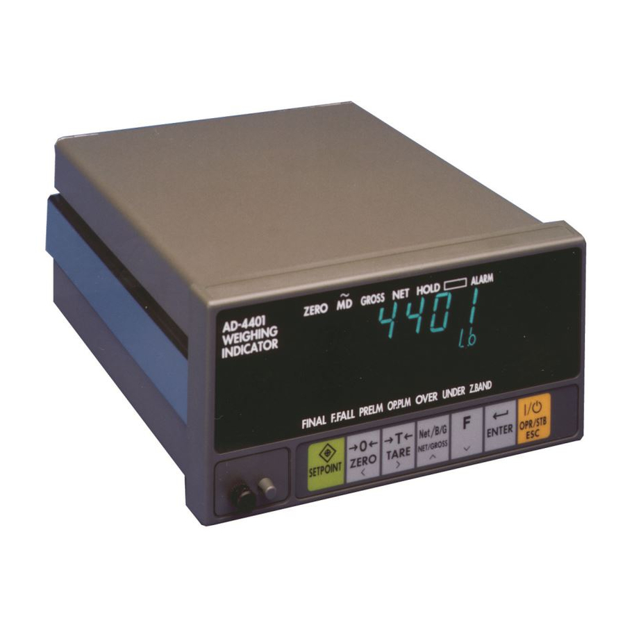
CHAPTER 1 GENERAL DESCRIPTION The AD-4401 is a compact-weighing indicator equipped with high-performance A/D conversion and general-purpose capabilities. It has the following features. User-friendly cabinet design • Small DIN size (panel dimensions: 138+1.0/-0 x 68+0.7/-0 mm) easy to mount in a control cabinet. •... -
Page 6: Chapter 2 Specifications
CHAPTER 2 SPECIFICATIONS 2-1 A/D CONVERTER BLOCK Input sensitivity 0.3 µV/D or more Zero correction range 0 to 20 mV ( 0 to 2mV/V) 10VDC +/- 5 %, 230 mA, with remote sensing capability (Up to eight 350 Load Cell Excitation ohm load cells can be connected) Zero point ±(0.2 µV + 0.0008 % of Dead Load ) / °C typ... -
Page 7: Accessories
WEIGHING CAPABILITIES Clears the gross to zero in compliance with a command from the ZERO keys, Control I/O, etc. Zero point Capable of enabling or disabling operations at unstable time. correcting capability Zero correction value is backed up by a battery. (Zero) Adjustable range: Can be freely set within 1 to 30 % of weighing capacity. -
Page 8: Front Panel
2-5 FRONT PANEL MAIN DISPLAY SECTION A 7-digit 7-segment display. Displays the gross, net weight, etc. SUB DISPLAY SECTION An 8-digit 7-segment display. The display content can be selected using the “general functions.” The display content is indicated by attaching an accessory label. STATUS DISPLAY SECTION (UPPER) The upper “-”... - Page 9 STATUS DISPLAY SECTION (LOWER) The lower “-” mark indicates a comparison result. In the normal mode, it is illuminated when a setpoint output of an identical name is turned on. In the setpoint setting mode, the “-” mark relevant to the value in the lower numerical display section blinks. Attach an accessory label depending on the weighing mode.
- Page 10 < Check Weighing > The meaning of each “-” mark differs completely. Attach a different accessory label. There are four kinds of Check Weighing. [Z.BAND] Illuminated when the gross weight is less than the zero band. [Lo-Lo] Blinks while setting the Lo-Lo. Illuminated when the comparison result output, Lo-Lo, is turned on.
- Page 11 KEY SWITCHES [CAL] The key used to enter the calibration mode. A cover is provided so that this key can not be operated if used in a certified commercial application. In order to prevent erroneous operation, attach and seal the cover. [SETPOINT] The key used to set a setpoint.
-
Page 12: Rear Panel
2-6 REAR PANEL (a) Connects the thumbwheel switch or setpoint unit (OP-05) to set a setpoint required for a weighing sequence. See 8-2 and 9-4. (b) Inputs/outputs the signals such as tare subtraction input, each loading output required for the weighing sequence. The capability of each terminal can be changed freely. -
Page 13: Chapter 3 Installation And Connections
CHAPTER 3 INSTALLATION AND CONNECTIONS This chapter describes the installation environment, and connections to the power terminals and load cell connector. For other external inputs/outputs, see their relevant descriptive chapters. Control I/O, Setpoint (SETPOINT), Standard serial output (SER. OUT) —— Chapter 8 Options ——... -
Page 14: Load Cell
6) To change a blown fuse. Turn the power off and wait 10 seconds or more. Replace the fuse with the accessory fuse without touching other parts. Make sure that no stray material is left in the case, screws, spacer, etc., before closing the case. 3-3 LOAD CELL For a load cell cable, the use of a 6 wire shielded cable is recommended in order to reduce weighing error. -
Page 15: Chapter 4 Operation
CHAPTER 4 OPERATION 4-1 OPERATION MODE This instrument has various “modes” in compliance with its operating conditions. Use the keys to change the mode. You can change the mode in the full-line arrow direction. The broken-line arrow direction indicates only an automatic reset after completion of setting or a reset by turning off the power. -
Page 16: Confirmation Of Operations
4-2 CONFIRMATION OF OPERATIONS The following outlines the procedure up to displaying a weight value in order to confirm operations after unpacking. Connect a load cell or load cell simulator to the proper terminals on the rear of the indicator. TURNING ON THE POWER * Do load cell wiring before turning on the power. -
Page 17: Setting A Setpoint
Step 12 The main display section displays “CAL SPn”, the Subdisplay section displays a weight value (current weighing capacity, set value for CALF-04), and the lowest digit of the weight value blinks. Adjust to the calibration weight value that you have on hand, using the [<], [>], and [ V ] keys. Step 13 Place the weight on the system, and press the [ENTER] key after the motion-detect mark is turned off. - Page 18 SETTING WITH THE KEY SWITCH (SPF-01 = 0) This method sets the setpoint using only the keys on the front panel. Step 1 Press the [SETPOINT] key in the normal mode. The indicator will switch to the setpoint setting mode. The “-”...
- Page 19 SETTING WITH THE 16-DIGIT THUMBWHEEL SWITCH (SPF - 01 = 2) This method assigns an exclusive thumbwheel switch to each setpoint. Some setpoints are set with the front panel keys without using the thumbwheel switch. Assignment of the thumbwheel switch and the front panel keys differs depending on the weighing mode (CALF-14) Since the setpoint assigned to the thumbwheel switch is read in real time, it can be referred to by key operation, but it cannot be altered.
-
Page 20: Chapter 5 Calibration
CHAPTER 5 CALIBRATION 5-1 GENERAL DESCRIPTION In the calibration mode, you carry out an operation, which associates a load cell output voltage with a weight value, and operations directly related to weighing. There are the following four kinds. Actual load calibration Calibration Modes: Calibration related functions Digital span... -
Page 21: Actual Load Calibration (Cal Set)
5-2 ACTUAL LOAD CALIBRATION (CAL SET) The zero point and span are calibrated using a calibration weight. When making calibration for the first time, it is necessary to set the unit, decimal point position, minimum division, and capacity in advance, using the calibration-related functions mentioned in 5-3. -
Page 22: Calibration Related Functions
5-3 CALIBRATION RELATED FUNCTIONS The calibration related functions are designed to set the basic constants for the indicator. They should be carried out first thing upon installation. Step 1 Remove the cover from the calibration switch located at the lower left of the front panel and press the [CAL] key (found inside). - Page 23 CALIBRATION RELATED FUNCTIONS Setting CALF- Name Default Parameter Description None g (International version) Weighing Unit kg ( International version and USA version) t (International version) lb. ( USA version) None 12345 1234.5 Decimal Point 123.45 Position 12.345 1.2345 Minimum 1, 2, 5, 10, Minimum division (increment) for the weight value.
- Page 24 Setting CALF- Name Default Parameter Description Motion Motion is detected in combination with CALF-09 Motion Detection 0.0 to 5.0 Detection Time Width. It is not detected when set to 0. Its unit is seconds. Motion Motion is detected in combination with CALF-08 Motion Detection Detection 0 to 9 Time.
- Page 25 0.000000 Zero Input Input Voltage (mV/V) from the Load Cell at "Zero", 0.000000 Voltage which is determined in "Zero Calibration" with weights. 2.200000 Span Input Input Voltage (mV/V) from the Load Cell at "Span", 0.000000 Voltage which means the difference between Capacity and 3.200000 (Capacity to Zero.
-
Page 26: Calibration Errors
5-4 CALIBRATION ERRORS Causes Solutions messages The minimum graduation is other than 1, 2, 5, CErr 0 Confirm setting of the minimum graduation, CALF-03. 10, 20, and 50. Resolution (weighing capacity/minimum Confirm the relations between the weighing capacity, CALF-04, and CErr 1 graduation) is more than 16000. -
Page 27: Chapter 6 General Functions
CHAPTER 6 GENERAL FUNCTIONS The general functions determine the operations of the AD-4401 and are all stored in the EEPROM. Each function is sorted into the groups by capabilities and represented by prefixing a function number (F-XX) with its group name. This chapter describes how to set the general functions and their details. -
Page 28: Basic Capabilities Related
6-1 BASIC CAPABILITIES RELATED Setting FNCF- Name Default Parameter Description Each bit corresponding to the relevant key. This function is 00000000 only available in Key switch 00000000 the normal disable 11111111 mode. All keys are usable if keys are enabled in the Control I/O (see6-3), Not disable... - Page 29 Setting FNCF- Name Default Parameter Description None “ “ "Discharging" is exclusively intended for Status display * discharging normal batching (built-in automatic Capability program mode). Zero tracking Value of each digit and cutoff frequency 0: None The digital filter is designed to suppress 1: 11.0Hz dispersion of a load cell output signal.
-
Page 30: Weighing Sequence Related
6-2 WEIGHING SEQUENCE RELATED Setting SQF- Name Default Parameter Description Selection of Internal count See 7-6 for details. comparison Display count weight No Automatic accumulation Automatic See 7-8 for details. Accumulates only acceptable accumulation weight Accumulates all values No automatic free fall compensation Only effective in Batch weighing mode... - Page 31 Setting SQF- Name Default Parameter Description Batch start wait Only effective in Built-In-Automatic timer Program mode. Full-flow Only normal batching(built-in automatic comparator program mode) is effective Inhibiter timer Intentionally blank Medium-flow comparator 0.0 to 25.5 (In Inhibiter timer step of 0.1 Dribble-flow second) comparator...
-
Page 32: Control I/O Input Related
6-3 CONTROL I/O INPUT RELATED INF-01 through INF-06 represents the input terminals A1 through A6, respectively. The content of setting is common to each terminal, but initial setting differs. INF-01: Capability of Input Terminal A1 INF-02 : Capability of Input Terminal A2 INF-03: Capability of Input Terminal A3 INF-04: Capability of Input Terminal A4 INF-05: Capability of Input Terminal A5... -
Page 33: Standard Serial Output Related
6-5 STANDARD SERIAL OUTPUT RELATED Setting SIF- Name Default Parameter Description Displayed weight Gross A & D standard format Tare Output Data Gross/Net/Tare Accumulated weight Accumulation data Accumulated counts format Accumulated weight /Accumulated counts Stream mode Data transmitting Auto-Print mode mode Manual-Print mode 600 bps... -
Page 34: Chapter 7 Weighing Sequence
CHAPTER 7 WEIGHING SEQUENCE 7-1 WEIGHING SEQUENCE GENERAL DESCRIPTION Weighing sequence, means to output control signals to the units connected to the Control I/O, etc., by means of input signals from the load cell and external unit. In order to cope with a wide range of applications, the AD-4401 has various weighing sequences. -
Page 35: Customer Programmed Control Mode
7-2 CUSTOMER PROGRAMMED CONTROL MODE NORMAL BATCHING (WEIGHING MODE: CALF-14 = 1) When an output condition is established, a relevant Output Terminal Output Condition output terminal is turned on (power continuity with Gross ≤ Zero band Zero band output COM). Net ≥... -
Page 36: Functional Description
LOSS-IN-WEIGHT (WEIGHING MODE CALF-14 = 2) Output Terminal Output Condition When an output condition is established, a relevant Gross ≤ Zero band Zero band output terminal is turned on (power continuity with Gross ≥ Full Full (Hopper Full) output COM). -Net ≥... -
Page 37: Built - In Automatic Program Mode
7-3 BUILT-IN AUTOMATIC PROGRAM MODE NORMAL BATCHING / NO SUPPLEMENTARY FLOW (WEIGHING MODE CALF-14 = 3) When an output condition is established, full flow, Output Terminal Output Condition medium flow, and dribble flow outputs are turned Gross ≤ Zero band Zero band off, but the other outputs are turned on. - Page 38 11. When the discharging valve close wait timer completes the set time, the discharging output signal is turned off. 12. When the Batch Start input signal for the next cycle is input; • The Batch Finish output signal is turned off. •...
- Page 39 NORMAL BATCHING/ WITH SUPPLEMENTARY FLOW (WEIGHING MODE CALF-14 = 3) Supplementary flow automatically turns on the dribble flow for the specified time when the loaded weight is not sufficient. To make supplementary flow, set the “maximum supplementary flow times, SQF-07,” to other than 0, and the “supplementary flow open timer, SQF-15,”...
- Page 40 13. When the discharging start wait timer completes the set time; • The discharging output signal is turned on, and the discharging time monitor timer starts. 14. When the gross becomes lower than the zero range; • The discharging valve close wait timer starts. •...
- Page 41 LOSS-IN-WEIGHT (WEIGHING MODE CALF-14 = 4) Output Terminal Output Condition When an output condition is established, medium Gross ≤ Zero band Zero band flow and dribble flow outputs are turned off, but the Gross ≥ Final - Full Full (Hopper full) other outputs are turned on.
- Page 43 SUPPLEMENTARY DESCRIPTION FOR BUILT-IN-AUTOMATIC PROGRAM MODE To subtract the tare automatically prior to loading Set the Batch Start wait timer to 0.1 second or more and connect the tare subtraction input and the Batch Start input in parallel. When using with a high-speed packer and it is difficult to stabilize after the judgment wait timer completes the set time Set stability at Judgment to “Unrequired.”...
- Page 44 7-4 SUPPLEMENTARY DESCRIPTION FOR BATCH WEIGHING When setting the setpoint with the 16-digit thumbwheel switch In batch batching, connection of the 16-digit thumbwheel switch is common. When SPF-01 = 2 is set, connect the thumbwheel switch to the SET POINT connector as show in the figure below. SETPOINT CONNECTOR WIRING Pin # Pin #...
-
Page 45: Check Weighing Mode
7-5 CHECK WEIGHING MODE CHECK WEIGHING MODE 1 (WEIGHING MODE CALF-14 = 5) Output Terminal Output Condition Gross ≤ Zero band Zero band When an output condition is established, a Hi-Hi Net > Hi-Hi limit relevant output terminal is turned on (power Net >... - Page 46 WHEN SETTING THE SETPOINT WITH A 15-DIGIT THUMBWHEEL SWITCH When SPF-01 = 2 is set, connect the thumbwheel switch to the SET POINT connector as show in the figure below. SETPOINT CONNECTOR WIRING Pin # Pin # Hi Limit. 10 Hi Limit.
- Page 47 CHECK WEIGHING MODE 2 (WEIGHING MODE CALF-14 = When an output condition is established, a relevant output terminal is turned on (power Output Output Condition continuity with output COM). Terminal Gross ≤ Zero band An output terminal number can Zero band be selected with the general Hi-Hi Net >...
- Page 48 WHEN SETTING THE SETPOINT WITH A 15-DIGIT THUMBWHEEL SWITCH When SPF-01 = 2 ( 16-digit mode ) is set, connect the thumbwheel switch to the SET POINT connector as show in the figure below. ;I <IKIQ ?AOGEQ REIGHQ 5 1 / . 5 1 / .
- Page 49 CHECK WEIGHING MODE 3 (WEIGHING MODE CALF-14 = 7) Output Terminal Output Condition When an output condition is established, a relevant Gross ≤ Zero band Zero band output terminal is turned on (power continuity with Hi-Hi Net > Hi-Hi Limit output COM).
- Page 50 WHEN SETTING THE SETPOINT WITH A 10-DIGIT THUMBWHEEL SWITCH When SPF-01 = 2 (16-digit mode) is set, connect the thumbwheel switch to the SET POINT connector as show in the figure below. <L <HJHP ;H <HJHP 5 1 / . 5 1 / .
- Page 51 CHECK WEIGHING MODE 4 (WEIGHING MODE CALF-14 = 8) Output Terminal Output Condition When an output condition is established, a relevant Gross ≤ Zero band Zero band output terminal is turned on (power continuity with output Hi-Hi Net > Hi-Hi Limit Hi Limit >...
- Page 52 WHEN SETTING THE SETPOINT WITH A 16-DIGIT THUMBWHEEL SWITCH When SPF-01 = 2 (16-digit mode) is set, connect the thumbwheel switch to the SET POINT connector as show in the figure below. =N ?NPNV =N -=N ?NPNV 6 2 0 / 6 2 0 / 6 2 0 / 6 2 0 /...
-
Page 53: Comparison Weight
7-6 COMPARISON WEIGHT Although the weight compared with the setpoint is mainly the net, the gross is partially compared. Since the net assumes a negative value in loss-in-weight, setpoint is made with the polarity reversed. Setpoint of the weight with the setpoint allows you to select the display count and internal count. One graduation of the weight value appearing in the display section is the minimum graduation set with CALF-03. -
Page 54: Automatic Free Fall Compensation
7-9 AUTOMATIC FREE FALL COMPENSATION Automatic free fall compensation is the capability to reduce a loading error in batch weighing. The following two kinds can be selected depending on the functioning of the automatic free fall compensation (SQF-03). 1) Automatically setting the “moving average of the last four actual free falls” as the free fall for the next weighing. -
Page 55: Chapter 8 Interface
CHAPTER 8 INTERFACE 8-1 CONTROL I/O The Control I/O is intended for inputting/outputting weighing control signals to an external unit. It consists of 6 inputs and 8 outputs. The capability of each input/output terminal can be selected, except COM (see 6-3, 6-4 for selection method). Upon shipment, the Control I/O terminals were set for normal batching (Built-in Automatic Program Mode). - Page 56 INPUT TERMINAL FUNCTION (INF-01 TO INF-06) The capabilities of the input terminals A1 through A6 can be optionally selected with the “general functions INF-01 through INF-06.” (See 6-3 for method of selection) Set value Terminal No. Function Name Description <No function> Clears the gross to zero.
- Page 57 OUTPUT TERMINAL FUNCTION (OUTF-01 TO OUTF-08) Output terminals B1 through B6 can be optionally selected with the “general functions OUTF-01 through OUTF-08.” (See 6-4.) Set value Function Name Description No function Zero range Turned on when the gross is close to the zero range. Underlimit In case of Normal batching/Loss-in-weight Hi-Hi...
-
Page 58: Setpoint
8-2 SETPOINT The setpoint refers to a weight setting such as the reference value and final required for the weighing sequence. Connect the thumbwheel switch which makes this setting to the SET POINT connector. Connection of the setpoint differs depending on the general function, “Setpoint Read Mode (SPF-01).” It also differs depending on the weighing mode. -
Page 59: Standard Serial Output (Ser. Out)
8-3 STANDARD SERIAL OUTPUT (SER. OUT) The standard serial output is a 20 mA current loop. It is located on the rear panel of the indicator, and is used to connect a remote indicator or printer. This output does not have a power supply. Therefore, the external unit must supply the power. - Page 60 OUTPUT DATA There are two kinds of transmission formats; “A & D standard format” and “Accumulation data format”. The A & D standard format has been used for our weighing indicators. It consists of two headers, data, unit, and terminator. The Accumulation data format outputs a simple header, numerical data, unit and terminator. The following shows their examples.
- Page 61 <ACCUMULATION DATA FORMAT> < Example > Header- 8 Digits Including Data, Polarity, and Decimal Point Unit Terminator Accumulated Header weight is "TW" Weight + "SP" Overflow value "SP" Weight - value, Overflow "-" polarity Accumulated Header count is "TN" Counts + "SP"...
-
Page 62: Chapter 9 Options
CHAPTER 9 OPTIONS There are the following external input/output options. Note) The 4401 has only one slot for OP-01, OP-03 or OP-04. Therefore only one of them can be installed. • OP-01 BCD output • OP-03 RS-422/-485 input/output • OP-04 RS-232C input/output •... - Page 63 INTERFACE SPECIFICATION Open collector (Common is connected to the NPN transistor emitter sides) Output Output data: 6-digit BCD code, overflow, polarity, motion, strobe Dry contact (Pulled up to +5 V by a resistor) Input Input data: Hold • In case of negative logic, each terminal is turned on at “1”. “ON” refers to the state that there is power continuity between the terminal and GND.
-
Page 64: Rs-422/-485 Interface
DATA TRANSFER MODE There are three kinds of data transfer modes for the BCD output; “stream,” “auto print,” and “manual print.” [Stream], [Auto Print], and [Manual Print] The functions of these transfer modes are the same as described in {8-3 Standard Serial Output}. TIMING Strobe pulses are turned on approximately 7 ms after rewriting the output data and turned off in 17 ms. - Page 65 <EXAMPLE> Note: • The polarity of signal A and B vary from computers. • Not necessary to ground the SG terminal for the computer without a signal ground terminal. • Wait 8 ms or more before selecting a unit by SDA and SDB.
-
Page 66: Rs-232C Input/Outputs
<EXAMPLE> The following is a program for connecting two AD-4401s and a computer by RS-422. Setting item Computer AD-4401 Baud rate 960 0 bps RSF-03 = 5 Parity bit Even RSF-04 = 2 Character bit 7 bits RSF-05 = 7 Stop bit length 1 bit RSF-06 = 1... - Page 67 Setting RSF- Name Default Parameter Description Displayed weight Gross A&D standard format Tare Output data Gross/Net/Tare Accumulated weight Accumulated data Accumulated counts format Accumulated weight/ Accumulated counts Stream Auto print Manual print Data Set to 9600 bps or less Command transfer at the time of output per Comparison data + Gross ;...
- Page 68 DATA TRANSFER MODE There are five kinds of data transfer modes for RS-232C/422/485; “stream,” “auto print,” “manual print,”,“command”, and “output per sampling.” [Stream], [Auto Print], and [Manual Print] The functions of these transfer modes are the same as described in 8-3 Standard Serial Output. [Command] This mode analyzes the “command”...
- Page 69 Accumulation data format Example Header 8 Digits Including Data, Polarity, and Decimal Point Unit Terminator Accumulated Header is weight "TW" Weight + "SP" Overflow value "SP" Weight - value, Overflow "-" polarity Accumulated Header is count "TN" Counts + "SP" Overflow value *The decimal point position remains unchanged in case of overflow.
- Page 70 HOW TO USE THE COMMAND MODE In the command mode, a “command” is transmitted from an external unit to the AD-4401, the AD-4401 operates in compliance with the command and responds with a result. When the command is not accepted due to an error (improper command or faulty data), a “negative acknowledgment”...
- Page 71 Type of Response Description Communication procedure A: Repeats the command as it is. Communication procedure B: Returns the data. Acknowledgment Communication procedure C: Returns the command as it is and waits to receive the data. Negative acknowledgment (Beyond condition): AD-4401 in non-receiving mode Negative acknowledgment (Beyond range): Data format correct, but value beyond allowable range...
-
Page 72: Setpoint Unit
9-4 OP-05 SETPOINT UNIT The OP-05 setpoint unit is a thumbwheel switch unit designed for setting the setpoints exclusive for Batch weighing and Loss-in-weighting use. By connecting this option to the AD-4401, each setpoint can be set with the thumbwheel switch on the panel or the BCD input. - Page 73 CONNECTION When the power supply is not connected, this instrument can be set with the thumbwheel switch on the front panel. When this is done, set the INT/EXT selector switches to INT. When the BCD input or serial connection is required, connect the power supply and short the CONT terminal.
- Page 74 USING THE EXTERNAL SETTING INPUT External setting input for final, free fall, and preliminary is enabled by setting their respective INT/EXT selector switches to EXT. It is of BCD code and negative logic, and its level is about 10 V. Drive it with an open collector input or no-voltage (shorting type) contact input.
-
Page 75: Analog Output
9-5 OP-07 ANALOG OUTPUT The OP-07 analog output option is for sending the weight data to an analog input unit. The output is a 4 to 20 mA current output proportional to the display reading. The output data is updated in synchronization with the display update. Setting ANF- Name... -
Page 76: Chapter 10 Maintenance
CHAPTER 10 MAINTENANCE 10-1 CHECK MODE ENTERING CHECK MODE The check mode is intended to check the operations of the indicator, key switches, and external input/output. With the [ENTER] key pressed and held, press the [SETPOINT] key. “Fnc” is displayed to indicate that the indicator is entering the general function mode. - Page 77 Item Checking procedures Display checked (O) Mark of the pressed key moves upward. Key Switches <Input terminal number> (O) Mark of the ON-terminal moves upward. <Output terminal number> Control I/O The terminal of the displayed number is on. Pressing the [ENTER] key sends “1 2 3 <CR><LF>” at the baud rate set Standard Serial in the general function setting.
-
Page 78: Initialization
10-2 INITIALIZATION Initialization is the operation to return the contents of the RAM and EEPROM to the initial factory values. There are three kinds of initialization modes, depending upon their ranges. Initializes the RAM only. Since the zero compensation value, tare value, setpoint, accumulated RAM initialization mode weight, and accumulated times are stored in the RAM, they are all cleared to zero. -
Page 79: Chapter 11 Setting Lists
CHAPTER 11 SETTING LISTS Use the settings list as a quick reference for maintenance of your AD-4401. When consulting with your A & D representative, let them know the user set values. 11-1 GENERAL FUNCTIONS BASIC FUNCTIONS Setting FNCF- Name User’s Default Parameter... - Page 80 WEIGHING SEQUENCE FUNCTIONS Setting SQF- Name User’s Default Parameter Description Selection of Internal count comparison Display count weight No Automatic accumulation Automatic Accumulates only acceptable weight accumulation Accumulates all values No automatic free fall compensation Only effective in Batch weighing mode Automatic free Moving average of last fall...
- Page 81 Setting SQF- Name User’s Default Parameter Description Dribble-flow comparator inhibitor timer 0.0 to 25.5 Judgment wait (In step of 0.1 0:Until next Batch timer second) Start Batch Finish Non-0: Set time output width Only effective in Batch 0.0 to 25.5 0: Unused Built-In-Automatic Program monitoring...
- Page 82 CONTROL I/O INPUT FUNCTIONS INF-01: Capability of Input Terminal A1 INF-02 : Capability of Input Terminal A2 INF-03: Capability of Input Terminal A3 INF-04: Capability of Input Terminal A4 INF-05: Capability of Input Terminal A5 INF-06: Capability of Input Terminal A6 Setting Default Parameter...
- Page 83 STANDARD SERIAL OUTPUT FUNCTIONS Setting SIF- Name User’s Default Parameter Description Displayed weight Gross A & D standard format Tare Output Data Gross/Net/Tare Accumulated weight Accumulated counts Accumulation data format Accumulated weight /Accumulated counts Data Stream mode transmitting Auto-Print mode mode Manual-Print mode 600 bps...
- Page 84 OP-03 RS-422 / OP-04 RS-232C FUNCTIONS Setting RSF- Name User’s Default Parameter Description Displayed weight Gross A&D standard format Tare Output data Gross/Net/Tare Accumulated weight Accumulated counts Accumulated data format Accumulated weight/ Accumulated counts Stream Auto print Manual print Data Set to 9600 bps or less Command transfer...
-
Page 85: Calibration Related Functions
11-2 CALIBRATION RELATED FUNCTIONS Setting CALF- Name User’s Default Parameter Description None g (International version) Weighing Unit kg ( International version and USA version) t (International version) lb ( USA version) None 12345 1234.5 Decimal Point 123.45 Position 12.345 1.2345 Minimum 1, 2, 5, 10, Minimum division(increment) for the weight value. - Page 86 Setting CALF- Name User’s Default Parameter Description Standard Serial Does not output when the weight value is overflowing Output; Output or unstable When Weight Value Is Overflowing or Outputs even if the weight is overflowing or unstable Unstable RS-232C/-422/-485 Does not output when the weight value is overflowing ;...
-
Page 87: Appendix Dimensions
APPENDIX DIMENSIONS AD-4401 OP-05...
Need help?
Do you have a question about the Weighing Indicator AD-4401 and is the answer not in the manual?
Questions and answers