Table of Contents
Advertisement
Advertisement
Table of Contents

Related Manuals for AND Multi Function Weighing Indicator AD-4402


Summary of Contents for AND Multi Function Weighing Indicator AD-4402
- Page 1 ふ Multi Function Weighing Indicator WM : PD4000243A This is a hazard alert mark.
- Page 2 This mark informs you about the operation of the product. Note This manual is subject to change without notice at any time to improve the product. No part of this manual may be photocopied, reproduced, or translated into another language without the prior written consent of the A&D Company.
-
Page 3: Table Of Contents
Contents Compliance..................4 1.1.1. Compliance with FCC rules ............4 1.1.2. Compliance with European Directives........4 Outline and Features ................. 5 2.1. Precaution ..................6 2.2. Front Panel ..................7 2.2.1. Keys ..................7 2.2.2. Symbols..................8 2.3. Rear Panel................... 10 Installation.................. - Page 4 6.3. System Design of a Hopper Scale..........34 6.3.1. Operation and I/O Design............34 6.3.2. Design Example ..............34 Weighing Mode................35 7.1.1. Contents of the Batch Weighing Mode ........35 7.2. Batch Weighing Mode ..............36 7.2.1. Selection of Batch Weighing............ 37 7.3.
- Page 5 8.3. Built-in Current Loop Output ............84 8.3.1. Connection ................84 8.3.2. Communication Modes............84 8.3.3. Data Format ................85 8.4. BCD Output of Option OP-01 ............85 8.5. Relay Output of Option OP-02............. 89 8.6. RS-422/485 Interface of Option OP-03........90 8.7.
-
Page 6: Compliance
1. 1. 1. 1. Compliance Compliance Compliance Compliance 1.1.1. 1.1.1. Compliance with FCC rules Compliance with FCC rules 1.1.1. 1.1.1. Compliance with FCC rules Compliance with FCC rules Please note that this equipment generates, uses and can radiate radio frequency energy. -
Page 7: Outline And Features
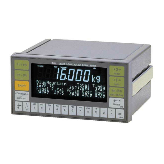
2. 2. 2. 2. Outline and Feature Outline and Feature Outline and Feature Outline and Features s s s The AD-4402 is a multi-function weighing indicator for batch weighing and filling weighing. This indicator has control I/O for weighing sequence and options. Large display This indicator has a blue vacuum fluorescent display (VFD). -
Page 8: Precaution
2.1. Precaution 2.1. Precaution 2.1. 2.1. Precaution Precaution Before use, confirm the following articles for safe operation. Grounding the indicator Ground the indicator. The earth terminal is on the rear panel. Separate this earth ground line from others, like ground line of a motor, inverter or a power source. -
Page 9: Front Panel
2.2. Front Panel 2.2. Front Panel 2.2. 2.2. Front Panel Front Panel Graphic status indicator Main display Weighing data is displayed. Status indicator Unit indicator Sub-display Materials, Total data, parameters and Standby indicator operation guidance are displayed 2.2.1. 2.2.1. 2.2.1. 2.2.1. -
Page 10: Symbols
The key to move the cursor or scroll the function number. Press and hold the SHIFT key and press the key to decrease the code number. The key to select alphabetical keys, upper keys, lower keys or numerical keys. Alphanumeric keys. The escape key. - Page 11 TARE ENT Tare entered. With the tare value stored, this sign is illuminated. HOLD With the main display held, this sign is illuminated. Center of zero. When the gross weight is in the center of the zero point, this sign is illuminated.
-
Page 12: Rear Panel
2.3. Rear Panel 2.3. Rear Panel 2.3. 2.3. Rear Panel Rear Panel Built-in RS-485 terminal. The possibility: to read weighing data, Loadcell terminal. write parameters, connect 32 units of the Eight 350 loadcells can be indicator using with the multi-drop connected in parallel. -
Page 13: Installation
3. 3. 3. 3. Installation Installation Installation Installation Caution Remove the power cord before installing the indicator and an option. Turn off peripheral devices before installing it. Insert the options before installing the indicator. 3.1. Mounting Indicator 3.1. Mounting Indicator 3.1. -
Page 14: Connecting Loadcell Cable
3.2. Connecting Loadcel 3.2. Connecting Loadcell Cable l Cable 3.2. 3.2. Connecting Loadcel Connecting Loadcel l Cable l Cable Caution Do not share the loadcell cable with noise-generating devices or power lines, beacuse the loadcell signal is very sensitive. We recommend that you use a 6 wire shielded cable to prevent loss of weighing precision. -
Page 15: Verifying Loadcell Output And Input Sensitivity
3.2.1. 3.2.1. Verifying Verifying Loadcell Output and Input Sensitivity Loadcell Output and Input Sensitivity 3.2.1. 3.2.1. Verifying Verifying Loadcell Output and Input Sensitivity Loadcell Output and Input Sensitivity The input sensitivity of the indicator is 0.3 V/division or more. Adapt to the following inequality, when you design a weighing instrument using the indicator and loadcell(s). -
Page 16: Wiring Power Cord
3.3. Wiring Power Cord 3.3. Wiring Power Cord 3.3. 3.3. Wiring Power Cord Wiring Power Cord Caution Gorund the indicator using terminal E to avoid receiving an electric shock or an error due to discharge of static electricity. Do not share the ground wire with an electrical device that generates noise. Do not use an unstable power source. -
Page 17: Installing Options
3.4. Installing Options 3.4. Installing Options 3.4. 3.4. Installing Options Installing Options Caution Remove the power cord before the operation to install an option. Do not install the same options. Do not touch the internal parts within ten seconds after removing the power cord because you may receive an electric shock. -
Page 18: Basic Operation
4. 4. 4. 4. Basic Operation Basic Operation Basic Operation Basic Operation 4.1. 4.1. Key Operation Exam 4.1. 4.1. Key Operation Exam Key Operation Exam Key Operation Examples ples ples ples This section describes the way of key operation. 4.1.1. 4.1.1. -
Page 19: The Way Of Calling A Code
4.1.4. 4.1.4. The Way of C The Way of Calling a Code alling a Code 4.1.4. 4.1.4. The Way of C The Way of C alling a Code alling a Code In Case of a Material Code: Step 1 Suppose that the function parameter [5qf- 8] to [0] is set. Step 2 Press the CODE RECALL key in the weighing mode. -
Page 20: The Way Of Entering The Menu
4.1.6. 4.1.6. The Way of Entering The Menu The Way of Entering The Menu 4.1.6. 4.1.6. The Way of Entering The Menu The Way of Entering The Menu Step 1 Press and hold the ENTER key and press the key in the weighing mode. Then the first layer of menu is displayed. -
Page 21: Status Chart (Mode Map)
4.2. Status Chart (Mode map 4.2. Status Chart (Mode map) ) ) ) 4.2. 4.2. Status Chart (Mode map Status Chart (Mode map AD-4402 Page 19... -
Page 22: Calibration
5. 5. 5. 5. Calibration Calibration Calibration Calibration The indicator, which is connected to a loadcell unit, can weigh the "weight" value on the loadcell pan and display its "mass" value. The calibration function is used to adjust the displayed value so that the weighing system can weigh correctly. There are two ways of calibration. -
Page 23: Actual Load Calibration (Using A Mass)
5.1. Actual Load Calibration (using 5.1. Actual Load Calibration (using a a a a Mass) Mass) 5.1. 5.1. Actual Load Calibration (using Actual Load Calibration (using Mass) Mass) ESC key If you want to return to the weighing mode during the calibration mode, press the ESC key anytime. -
Page 24: Digital Span (Calibration Without A Mass)
5.2. Digital Span (Calibration without 5.2. Digital Span (Calibration without a a a a Mass) Mass) 5.2. 5.2. Digital Span (Calibration without Digital Span (Calibration without Mass) Mass) ESC key If you want to return to the weighing mode during the calibration mode, press the ESC key anytime. -
Page 25: Gravity Acceleration Correction
5.3. Gravity Acceleration Correction 5.3. Gravity Acceleration Correction 5.3. 5.3. Gravity Acceleration Correction Gravity Acceleration Correction The function compensates for weighing error due to the difference of gravity acceleration. The place where the weighing system is calibrated. The place where the weighing system is used. ESC key If you want to return to the weighing mode during the calibration mode, press the ESC key anytime. -
Page 26: Calibration Error
5.4. Calibration Error 5.4. Calibration Error 5.4. 5.4. Calibration Error Calibration Error Error Code Situation and Treatment CERR1 Resolution (Weighing capacity / minimum division) exceeds the limitation. Increase minimum division or decrease weighing capacity. CERR2 The initial load (no load output) is larger than 2mV/V. Check the loadcell cable. -
Page 27: Applications
6. 6. 6. 6. Applications Applications Applications Applications 6.1. 6.1. Hopper Scale with Material Code 6.1. 6.1. Hopper Scale with Material Code Hopper Scale with Material Code Hopper Scale with Material Code In the section, applications are explained according to the right hopper scale that performs batch weighing using a material code. -
Page 28: Editing Principle Parameters Of A Material Code
6.1.3. 6.1.3. Editing Principle Parameters of a Material Code Editing Principle Parameters of a Material Code 6.1.3. 6.1.3. Editing Principle Parameters of a Material Code Editing Principle Parameters of a Material Code You can edit the parameters of final weight, free fall etc. displayed on the sub-display during a weighing. -
Page 29: Editing Full Parameters Of A Material Code
6.1.5. 6.1.5. Editing Full Parameters of a Material Code Editing Full Parameters of a Material Code 6.1.5. 6.1.5. Editing Full Parameters of a Material Code Editing Full Parameters of a Material Code A material code consists of the following parameters. Display Name Display Display... - Page 30 Search a Material Code Use this menu to search for blank material code. Step 1 Press and hold the ENTER key and press the key. MatEdit Then menu blinks. Search Step 2 Press the key to select menu . And press the ENTER key. Step 3 Then the message is displayed.
- Page 31 Tare of a Material Code Use to copy a current tare to the preset tare. Set the preset tare function [genf-12 ] of the function list. [genf-12] [0] If the preset tare of the code is zero, the last tare value is in effect. (factory settings) [genf-12] [1] If the preset tare of the code is zero, the tare value is reset.
-
Page 32: Simple Hopper Scale With A Recipe Code
6.2. Simple Hopper Scale with a Recipe Code 6.2. Simple Hopper Scale with a Recipe Code 6.2. 6.2. Simple Hopper Scale with a Recipe Code Simple Hopper Scale with a Recipe Code This section explains for the recipe code. The recipe code is used on a simple hopper scale to mix several materials that have preset final values. -
Page 33: Using A Recipe Code
6.2.2. 6.2.2. Using a Recipe Code Using a Recipe Code 6.2.2. 6.2.2. Using a Recipe Code Using a Recipe Code Set the menu [Function] - [Function setting] - [Sequence] - [Basic] - [Recipe mode] to sequential mode ( [5q f- 8] to [1] or [2] ), when the recipe code is used. [5q f- 8] [1] Semi-automatic mixing sequence [5q f- 8] [2]... -
Page 34: Arranging Material Code In A Recipe Code
6.2.5. 6.2.5. Arranging Material Code in a Recipe Code Arranging Material Code in a Recipe Code 6.2.5. 6.2.5. Arranging Material Code in a Recipe Code Arranging Material Code in a Recipe Code The way of arranging the material code described in a recipe code. Step 1 Press and hold the ENTER key and press the CODE RECALL key. - Page 35 Total value Recipe total value All total values All Recipes Example of Deleting a Total Value Step 1 Press and hold the ENTER key and press the key. RecipeEDIT Then the menu blinks. Delete Step 2 Press the key to select the menu .
-
Page 36: System Design Of A Hopper Scale
6.3. System Design of a Hopper Scale 6.3. System Design of a Hopper Scale 6.3. 6.3. System Design of a Hopper Scale System Design of a Hopper Scale 6.3.1. 6.3.1. 6.3.1. 6.3.1. Operation and I/O Design Operation and I/O Design Operation and I/O Design Operation and I/O Design In General, looking at an old type hopper scale design, the simplest indicator only... -
Page 37: Weighing Mode
7. 7. 7. 7. Weighing Mode Weighing Mode Weighing Mode Weighing Mode 7.1.1. 7.1.1. Contents of the Contents of the Batch Batch Weighing Mode Weighing Mode 7.1.1. 7.1.1. Contents of the Contents of the Batch Batch Weighing Mode Weighing Mode Batch Weighing Normal Batching Section 7.2... -
Page 38: Batch Weighing Mode
7.2. Batch 7.2. Batch Weighing Mode Weighing Mode 7.2. 7.2. Batch Batch Weighing Mode Weighing Mode This mode is used to get a (constant) final weight from a supplying hopper for the hopper scale and filling machine. And mode can be classified as normal batch weighing or loss-in-weigh. -
Page 39: Selection Of Batch Weighing
7.2.1. 7.2.1. Selection of Batch Weighing Selection of Batch Weighing 7.2.1. 7.2.1. Selection of Batch Weighing Selection of Batch Weighing Selection of Normal Batching or Loss-in-weigh Loss-in-weigh The mode can be selected at in the Function list. ([Function] - [Function setting] - [Sequence] - [Basic] - [Current weighing]) [5q f- 3] [0] Normal batch weighing [5q f- 3] [1]... - Page 40 [ Blank page] Page 38 AD-4402...
-
Page 41: Built-In Automatic Program Mode
7.3. Built 7.3. Built- - - - in in in in A A A A utomatic utomatic P P P P rogram rogram M M M M ode 7.3. 7.3. Built Built utomatic utomatic rogram rogram The built-in automatic program mode directly outputs control signals (example: medium flow valve, batch finish) without a PLC. -
Page 42: Normal Batching Of Built-In Automatic Program Mode
7.3.1. 7.3.1. 7.3.1. 7.3.1. N N N N ormal ormal ormal B B B B atching of Built ormal atching of Built atching of Built atching of Built- - - - in automatic in automatic in automatic in automatic program mode program mode program mode program mode... - Page 43 Using customer programmed control for OVER signal, OK signal and UNDER signal. [5q f- 5] [Function] - [Function setting] - [Sequence] - [Basic] - [Comparison] Displayed value Preliminary Gross weight Final value (Target weight) Net weight Final value - Free fall Free fall Final value - Preliminary Final value - Optional preliminary...
-
Page 44: Loss-In-Weigh Of The Sequential Mode
7.3.2. 7.3.2. Loss Loss- - - - in in in in- - - - weigh weigh of of of of the the Sequential Sequential Mode Mode 7.3.2. 7.3.2. Loss Loss weigh weigh Sequential Sequential Mode Mode Loss-in-weigh weighs the material discharged from the hopper. Control gates (valves) can be used. - Page 45 Displayed value Full value Gross weight Full Zero band Net weight Final value - Final value + Optional preliminary - Final value + Preliminary Preliminary - Final value + Free fall Optional preliminary - Final value or -Target weight Free fall The active code is only read at Enable automatic tare to use each start.
-
Page 46: Compensation Sequence
7.3.3. 7.3.3. C C C C ompensation ompensation S S S S equence equence 7.3.3. 7.3.3. ompensation ompensation equence equence The compensation sequence is used to make up (add) the material automatically, when the result of the current batch weighing is under weight. Concerning Parameters of the Function Storing a maximum repeat count of the compensation sequence. - Page 47 Displayed value Preliminary Free fall Under weight Final value (Target weight) Net weight Optional preliminary Material code, Input Start command, Input Time until supplying it The whole time to 5qf-32 supply it Batch start delay timer 5qf-31 Batch monitoring timer Full flow, Output Medium flow, Output Dribble flow, Output...
-
Page 48: Initial Flow Sequence
7.3.4. 7.3.4. Initial Flow S Initial Flow Sequence equence 7.3.4. 7.3.4. Initial Flow S Initial Flow S equence equence The initial flow sequence is used to prevent the material from scattering before the batch weighing when a liquid or powder is weighed. When the sequence starts, the dribble gate is opened first, the medium gate is opened next and the full gate is opened last. - Page 49 Displayed value Gross weight Dribble Final value (Target weight) Net weight Free fall Preliminary Initial MF Initial DF Material code, Input Start command, Input Time until supplying it 5qf-32 The whole time to Batch start delay timer supply it 5qf-31 Batch monitoring timer Full flow, Output Medium flow, Output...
-
Page 50: Discharge Sequence
7.3.5. 7.3.5. Discharge Discharge S S S S equence equence 7.3.5. 7.3.5. Discharge Discharge equence equence The discharge sequence is used to discharge the material from the hopper and clear the hopper after finishing a batch weighing. Concerning Parameters of the Function Storing the time between receiving a start command and opening the discharge gate. - Page 51 Displayed value Gross weight Net weight Gross value crosses zero band. Zero band Zero band. Start command, Input Start delay timer Full flow, Output Medium flow, Output Compari s on Dribble flow, Output Eval delay timer Stable, Output Batch finish, Output Automatic discharge When displayed value has operation can select...
-
Page 52: Recipe Sequence
7.3.6. 7.3.6. R R R R ecipe ecipe S S S S equence equence 7.3.6. 7.3.6. ecipe ecipe equence equence The recipe sequence mixes preset final weights of multiple materials that are stored in a recipe code. One hundred recipe codes can be stored in the indicator. A recipe code can store ten material codes and the order to mix them. - Page 53 Displayed value Net weight Gross weight The active recipe code The material code can is only read at each not be edited during the start. And keep it. recipe mode. Recipe code, Input Recipe code 1 Recipe code 2 Material code1 Material code2 Material code3 Material code, Output Zero before the recipe...
-
Page 54: Automatic Selection Of Supplying Hopper
7.3.7. 7.3.7. Automatic Selection of Supplying Hopper Automatic Selection of Supplying Hopper 7.3.7. 7.3.7. Automatic Selection of Supplying Hopper Automatic Selection of Supplying Hopper When there are multiple supplying mats of materials, the indicator has to control these gates. There are the following two method to control them. Case 1: Direct Gate Control The method that connects the gate control lines of supplying hoppers to the I/O terminals of the indicator and the indicator directly controls them. -
Page 55: Nozzle Control Sequence (Vacuum Cleaner)
7.3.8. 7.3.8. Nozzle Control Sequence ( Nozzle Control Sequence (vacuum cleaner vacuum cleaner) ) ) ) 7.3.8. 7.3.8. Nozzle Control Sequence ( Nozzle Control Sequence ( vacuum cleaner vacuum cleaner The nozzle is used for filling a bottle with a liquid or powder. The procedure inserts the nozzle into the bottle automatically using the signal "nozzle down"... -
Page 56: Mixing Sequence
7.3.9. 7.3.9. Mixing Sequence Mixing Sequence 7.3.9. 7.3.9. Mixing Sequence Mixing Sequence The mixing sequence is used to mix or stir material. The signal is output from the I/O terminal set to mixing. The timing of batch finish, discharge finish and recipe finish can be selected. - Page 57 Displayed value Gross weight Net weight material 2 material 3 material 1 Recipe start command, Input Full flow, Output Medium flow, Output Dribble flow, Output Batch finish, Output Recipe finish, Output 5qf-47 5qf-17 Mixing timer Set "automatic mixing start" Mixing, Output to continue the mixing.
-
Page 58: Safety Check Function
7.3.10. 7.3.10. Safety Safety Check Check Function Function 7.3.10. 7.3.10. Safety Safety Check Check Function Function This function is used to stop the sequence when an error or an emergency happens. When the function works, an error code is displayed and an error signal is output from weighing sequence error the preset I/O terminal that [22] is selected at... -
Page 59: Restart Sequences From Pause
7.3.12. 7.3.12. Restart Sequences from Pause Restart Sequences from Pause 7.3.12. 7.3.12. Restart Sequences from Pause Restart Sequences from Pause The restart input was used to start from the point that is stopped in the last sequence. The control inputs of the function use the preset I/O terminals or OP-05 terminals that Restart select The action of the function is as follows:... -
Page 60: Automatic Free Fall Compensation
7.3.13. 7.3.13. Automatic Fre Automatic Free Fall Compensation e Fall Compensation 7.3.13. 7.3.13. Automatic Fre Automatic Fre e Fall Compensation e Fall Compensation This function arranges the free fall parameter using the average of the last four displayed values so as to get a more precise weighing. Concerning Parameters of the Function Using the automatic free fall compensation [5q f-20] [1]... -
Page 61: Real Time Free Fall Compensation
7.3.14. 7.3.14. Real Time Free Real Time Free Fall Compensation Fall Compensation 7.3.14. 7.3.14. Real Time Free Real Time Free Fall Compensation Fall Compensation This function arranges the free fall parameter to get more precise weighing during the sequence (in real-time calculation). Example: this function fits a liquid weighing (water, cement, tar) that flow rate is not constant due to temperature, viscosity and the remains. - Page 62 [ Blank page] Page 60 AD-4402...
-
Page 63: Customer Programmed Control (Comparison Output)
7.4. C C C C ustomer 7.4. ustomer P P P P rogram rogrammed med C C C C ontrol ontrol (C (C (C (Comparison omparison Output Output) ) ) ) 7.4. 7.4. ustomer ustomer rogram rogram ontrol ontrol omparison omparison Output Output... - Page 64 7.4.1. 7.4.1. 7.4.1. 7.4.1. Normal Batching of the C Normal Batching of the C Normal Batching of the C Normal Batching of the Customer ustomer ustomer ustomer P P P P rogram rogrammed med C C C C ontrol ontrol Mode Mode rogram rogram...
- Page 65 Displayed value Gross weight Free fall Net weight Full value Dribble Preliminary Zero band The active recipe code is only read at each start. And keep it. Material code, Input Full flow, Output Medium flow, Output Dribble flow, Output These gates work 5qf-33...
-
Page 66: Normal Batching Of The Customer Programmed Control Mode 62 7.4.2. Loss-In-Weigh Of The Customer Programmed Control Mode
7.4.2. 7.4.2. 7.4.2. 7.4.2. Loss Loss Loss Loss- - - - in in in in- - - - weigh of the C weigh of the C weigh of the Customer weigh of the C ustomer ustomer ustomer P P P P rogram rogram rogrammed rogram... - Page 67 Advise Using the automatic switch of normal batch and loss-in-weigh. Specify the output terminal for the hopper number in the material code on the I/O. Specify the input terminal to change the mode on the I/O. [1n f-nn] [9] Connect the output terminal to the input terminal. Connect the output common terminal to the input common terminal.
-
Page 68: Other Functions
7.5. Other Functions 7.5. Other Functions 7.5. 7.5. Other Functions Other Functions 7.5.1. 7.5.1. 7.5.1. 7.5.1. Re- - - - Zero Zero Zero Zero Operation Operation Operation Operation Performing this function, a gross display is zeroed and the current displayed value is used as a standard point. -
Page 69: Tare
7.5.3. 7.5.3. Tare Tare 7.5.3. 7.5.3. Tare Tare The relation of the display is as follows: Net = Gross - Tare Concerning Parameters of the Function Prohibiting tare during unstable weighing [genf- 9] Tare and zero compensation at unstable status [Function] - [Function setting] - [General] - [Weighing] Prohibiting tare during negative weighing Tare at negative GROSS weight... -
Page 70: Customizing The Sub Display
7.5.6. 7.5.6. Customizing the Sub Display Customizing the Sub Display 7.5.6. 7.5.6. Customizing the Sub Display Customizing the Sub Display Use the default sub-display pattern, if you want to reset it. Refer to "10.4. Parameter List" of the function list regarding these items. Item index number to be displayed. -
Page 71: Graphic Display
Number Name and Number to Display the Item Row size Columsize Figures Automatic Free Fall Compensation Internal reserved Internal reserved Initial dribble flow Initial dribble flow Total weight Total count Recipe , rCode Total weight for recipe mode Total counts for recipe mode Concerning Parameters of the Function Setting the sub-display [5ubf- 1] [1]... -
Page 72: Total Operation
7.5.8. 7.5.8. Total Total Operation Operation 7.5.8. 7.5.8. Total Total Operation Operation Total weight data and weighing count of each material code or recipe code. Concerning Parameters of the Function Using F1 ~ F4 key for total [0tHf- 2] to [0tHf- 5] [Function] - [Function setting] - [General] - [Other] Using the I/O terminals for total [1n f-nn]... -
Page 73: Error Message And Alarm
7.5.11. 7.5.11. Error Message Error Message and Alarm and Alarm 7.5.11. 7.5.11. Error Message Error Message and Alarm and Alarm When the indicator detects an error in the weighing system, an error message is displayed. When the indicator becomes a preset condition, it is announced with the preset alarm. Kind of error Error no. - Page 74 Kind Description When the displayed value can not be set to zero with re-zero or tare, the message is displayed. Zero error ZR.ERR Dispaly can not be zeroed by zero compensation. Dispaly can not be zeroed by tare operation. When the weighing value is out of range and emergency stop is performed, this symbol is displayed.
-
Page 75: Graphic Status Indicator
7.5.12. 7.5.12. Graphic Status Indicator Graphic Status Indicator 7.5.12. 7.5.12. Graphic Status Indicator Graphic Status Indicator The indicator can display weighing status, result on the graphic indicator. Graphic indicator Over Under Full flow Medium flow Dribble flow Concerning Parameters of the Function Using the graphic indicator [5ubf- 5] Activity indicator... -
Page 76: Interface
8. 8. 8. 8. Interface Interface Interface Interface 8.1. 8.1. Control I/O Function 8.1. 8.1. Control I/O Function Control I/O Function Control I/O Function Input terminals 11 lines that can select by the function Output terminals 11 lines that can be selected by the function Open collector transister Input terminal Maximum... -
Page 77: Timing Chart
The function assigned to terminals The function of the terminal can be assigned arbitrarily. Refer to "10.4. Parameter List" of the function list 8.1.2. 8.1.2. 8.1.2. 8.1.2. Timing Chart Timing Chart Timing Chart Timing Chart Caution Keep the delay time to avoid abnormal-operation and noise. Keep the input signal more than 40 ms to avoid noise and chattering. -
Page 78: Built-In Rs-485 Interface
8.2. Built 8.2. Built- - - - in RS in RS- - - - 485 Interface 485 Interface 8.2. 8.2. Built Built in RS in RS 485 Interface 485 Interface The RS-485 interface can use commands to control the indicator. The interface can read weighing data or parameters and store parameters in the indicator. -
Page 79: Settings Of Parameters
The host computer may have inverse polarity terminals. The host computer may include Terminator resistor 100 ~ 120 1/2W the terminator resistor. Host computer AD-4402 Address 1 Use twisted-pair wire. Use shielded cable, if it is needed. AD-4402 Address 2 Connect a terminator resistor at the indicator that is longest distance from the host computer. -
Page 80: Timing Chart
8.2.3. 8.2.3. Timing Chart Timing Chart 8.2.3. 8.2.3. Timing Chart Timing Chart Keep the delay time above 0.5 ms between the last response and the next command. [r5 f- 9] < tr < [r5 f- 9] + 50 ms Set response time (tr). Use a long delay time, when there is noise. -
Page 81: General Data Format
8.2.4. 8.2.4. Genera General Data Format l Data Format 8.2.4. 8.2.4. Genera Genera l Data Format l Data Format This format is used for the command mode and jet stream mode. 10 11 14 15 21 22 24 25 R G R S 0 0 9 9 1 2 3 4 5 6 7 1 2 3 4 5 6 7 8 9... -
Page 82: A&D Data Format
8.2.5. 8.2.5. A&D Data Format A&D Data Format 8.2.5. 8.2.5. A&D Data Format A&D Data Format This format is used for stream mode, auto print mode and total print. This format is compatible to the AD-4325 indicator. Header 1 Header 2 Weighing data Terminator Unit... -
Page 83: Command List
8.2.7. 8.2.7. Command List Command List 8.2.7. 8.2.7. Command List Command List Monitor Commands Name Code Description RDSP Read displayed value Read gross data RGRS Read net value RNET Read tare value RTAR RFIN Read weighing result RSPTxxxx Read setpoint or RSPT#### Read comparison parameters RSxx... - Page 84 Control Commands Name Code Description CZER Make zero display Make zero clear CCZR CTAR Tare CCTR Tare clear CGRS Change to gross display CENT Change to net display CCODxxxx Call material code CCxx Call recipe code CRCDxxxx CACC Total command CCAC Cancel the last result CBAT...
- Page 85 Response Error Code Response Description Note The format of command is not correct. When an address is used, The data of command is not correct. address is appended to the response. Indicator is busy. ASCII Code for AD-4402 The characters are special code for the name of material code and recipe code. Therefor, some characters are not the same as U.S.
-
Page 86: Built-In Current Loop Output
8.3. Built 8.3. Built- - - - in Current Loop in Current Loop Output Output 8.3. 8.3. Built Built in Current Loop in Current Loop Output Output Transmission system EIA RS-232C, Asynchronous, bi-directional, half-duplex Current 1 = 20mA, 0 = 0 mA, external DC current source Data length 7 bits Start bit... -
Page 87: Data Format
8.3.3. 8.3.3. Data Format Data Format 8.3.3. 8.3.3. Data Format Data Format The format is the same as A&D format of the built-in RS-485. 8.4. 8.4. BCD Output 8.4. 8.4. BCD Output BCD Output BCD Output of Option OP of Option OP of Option OP of Option OP- - - - 01 Output circuit... - Page 88 Terminals When weighing display, gross display, net display or tare display [01f- 1] [1, 2, 3, 4] is used, the function of the terminals are as follows: Unit Unit 1 Unit 2 blank 0 1,000 2,000 4,000 8,000 10,000 80,000 40,000 80,000 100,000...
- Page 89 When recipe code and material code [01f- 1] [9] are used, the function of the terminals are as follows: Material code at 1 B1 Material code at weighing weighing sequence 4 B2 sequence 10 B3 40 B4 Referred 1 B5 Referred material code material code 4 B6...
- Page 90 Communication Modes There are the following modes. Stream Mode The data is output at every display update. If the data can not be output completely due to slow baud rate, the data is output at the next update. Auto Print Mode The data is printed at batch finish and recipe finish automatically.
-
Page 91: Relay Output Of Option Op-02
8.5. Relay Output 8.5. Relay Output of Option OP of Option OP- - - - 02 8.5. 8.5. Relay Output Relay Output of Option OP of Option OP Rated load 250 V AC, 3 A 30 V DC, 3 A Current at common terminal Max. -
Page 92: Rs-422/485 Interface Of Option Op-03
8.6. RS 8.6. RS- - - - 422/485 Interface of Option OP 422/485 Interface of Option OP- - - - 03 8.6. 8.6. 422/485 Interface of Option OP 422/485 Interface of Option OP The RS-422/485 interface can use commands to control the indicator. The interface can read weighing data or parameters or store parameters to the indicator. - Page 93 RS-422 Connections [03 f-11] [1] Settings RS-422 [03 f- 8] [0]. Address Number 0 Terminator resistor 100 ~ 120 1/2W Host computer SDA 1 SDB 2 RDA 3 RDB 4 The host computer may include SG 5 the terminator resistor. FG 6 TERMINATOR The host computer may have...
- Page 94 RS-485 2 Wire Connections [03 f-11] [2] Settings RS-485 The host computer may include Terminator resistor the terminator resistor. 100 ~ 120 1/2W Host computer The host computer may have inverse polarity terminals. TERMINATOR AD-4402 No.1 2 (SDA) and 3 (SDB) connect nothing.
-
Page 95: Rs-232C Interface Of Option Op-04
8.7. RS 8.7. RS- - - - 232C Interface of Option OP 232C Interface of Option OP- - - - 04 8.7. 8.7. 232C Interface of Option OP 232C Interface of Option OP The RS-232C are used to connect to the DEC (modem). The command and parameters of RS-232C is the same as the built-in RS-485. -
Page 96: Parallel I/O Of Option Op-05
8.8. Parallel I/O of Option OP 8.8. Parallel I/O of Option OP- - - - 05 8.8. 8.8. Parallel I/O of Option OP Parallel I/O of Option OP Use this option to extend the I/O terminals The function, settings, interface circuit and timing chart of the option is the same as the built-in I/O terminal. -
Page 97: Analog Output Of Option Op-07
8.9. Analog Output of Option OP 8.9. Analog Output of Option OP- - - - 07 8.9. 8.9. Analog Output of Option OP Analog Output of Option OP This option outputs DC current that is proportion to the display value. Factory adjusted to 4 mA output at zero display and 20 mA output at full scale. -
Page 98: Maintenance
9. 9. 9. 9. Maintenance Maintenance Maintenance Maintenance 9.1.1. 9.1.1. Basic Operation Basic Operation 9.1.1. 9.1.1. Basic Operation Basic Operation To enter the maintenance function Press and hold the ENTER key and press the key in the weighing mode. maintenance Select the menu using the and the ENTER key. -
Page 99: Monitoring The Built-In Current Loop Output
9.2.3. 9.2.3. Monitoring the Built Monitoring the Built- - - - in Current Loop Output in Current Loop Output 9.2.3. 9.2.3. Monitoring the Built Monitoring the Built in Current Loop Output in Current Loop Output The current communication data is displayed. Parity: p Received data Framing: f... -
Page 100: Monitoring The Rs-422/485 Interface Of Op-03
9.2.7. 9.2.7. Monitoring the RS Monitoring the RS- - - - 422/485 Interface of OP 422/485 Interface of OP- - - - 0 0 0 0 3 3 3 3 9.2.7. 9.2.7. Monitoring the RS Monitoring the RS 422/485 Interface of OP 422/485 Interface of OP The current communication data is displayed. -
Page 101: Test Mode
9.3. Test Mode 9.3. Test Mode 9.3. 9.3. Test Mode Test Mode The test mode is used to check the indicator and weighing system with a test signal. When the test mode is used, the weighing sequence is stopped. Caution The test mode outputs a test signal. -
Page 102: Testing The A/D Converter
9.3.4. 9.3.4. Testing the A/D Converter Testing the A/D Converter 9.3.4. 9.3.4. Testing the A/D Converter Testing the A/D Converter The A/D converter data is displayed. When pressing the ENTER key, a test voltage can be input to the A/D converter. 16 . -
Page 103: Testing The Rs-232C Interface Of Op-04
9.3.8. 9.3.8. Testing the RS Testing the RS- - - - 232C Interface of OP 232C Interface of OP- - - - 04 9.3.8. 9.3.8. Testing the RS Testing the RS 232C Interface of OP 232C Interface of OP When pressing the ENTER key each time, the test data "ST,GS,+0000000kg CR LF" is output. -
Page 104: Initializing Parameters
9.4. Initializing Parameters 9.4. Initializing Parameters 9.4. 9.4. Initializing Parameters Initializing Parameters This function initializes the parameters stored in the indicator. The parameters are stored in the flash memory and backup RAM. Caution There are reset functions that require re-calibration of the indicator Note where the parameters are stored. - Page 105 Prucedure Caution Do not initialize them while in operation. Cut off the power supply of other systems. When initializing the indicator, the output may change. When initializing the indicator, do not turn it off before it is reset. To enter initialization Step 1 Press and hold the ENTER key and press the key to display the menu in a weighing mode.
-
Page 106: Remote Operation
9.5. Remote Operation 9.5. Remote Operation 9.5. 9.5. Remote Operation Remote Operation This mode can read and write the parameters of the function list, data of the material code and recipe code and calibration data. The built-in RS-485, RS-422/485 (OP-03) or RS-232C (OP-04) is used for remote operation. -
Page 107: Function List
10. Function List Function List Function List Function List The function list stores parameters to control the indicator. The parameters are stored in an item even without power supplied. An item is classified by a category address, and is further classified by an item number. -
Page 108: Outline Of The Function List
10.1.2. 10.1.2. Outline of the Function List Outline of the Function List 10.1.2. 10.1.2. Outline of the Function List Outline of the Function List Category Address Start Item Function Function reference General genf- 1 Weight 5ub f 1 Sub display othf- 1 Other Sequence... -
Page 109: Referring Parameters
10.2. Referring 10.2. Referring Parameters Parameters 10.2. 10.2. Referring Referring Parameters Parameters Use this mode to refer to the parameter in the weighing sequence. The mode can change the parameters concerning the digital filter and weighing sequence timers in the weighing sequence. [genf- 2] Digital filtering [Function] - [Function setting] - [General] - [Weighing]... -
Page 110: Parameter List
10.4. Parameter List 10.4. Parameter List 10.4. 10.4. Parameter List Parameter List Category address: [Function] - [Function setting] - [General] - [Weighing] Category Range address Name Descriptions Default symbol choices 1: Five times per second genf- 1 Display refresh rate 1 to 2 2: Ten times per second 0: Not used... - Page 111 Category Range address Name Descriptions Default symbol choices The action at turning the indicator on. First bit: Zero Second bit: Zero clear Clear mode at Third bit: Tare 0000 to genf-13 0000 power ON Fourth bit: Tare clear 1111 0: Not used 1: Use 1: Hold genf-14...
- Page 112 Category address: [Function] - [Function setting] - [General] - [Sub-display] Category Range address Name Descriptions Default symbol choices 0: Basic format 5Ubf- 1 Weighing display 0 to 1 1: Custom format When custom format is used (When [5Ubf- 1] [1] ), set items to be displayed in the sub-display.
- Page 113 Category address: [Function] - [Function setting] - [General] - [Sub-display] Category Range address Name Descriptions Default symbol choices 0: Basic format 5Ubf- 2 Recipe display 0 to 1 1: Custom format When custom format is used (When [5Ubf- 2] [1] ), set items to be displayed in the sub-display.
- Page 114 Category address: [Function] - [Function setting] - [General] - [Sub-display] Category Range address Name Descriptions Default symbol choices 5ub f 1 Refer to previous pages. 5ub f 2 0: Hide 5ub f 3 Bar graph location 1: Upper side. 0 to 2 2: Lower side.
- Page 115 Category Range address Name Descriptions Default symbol choices 0: Not used 1: Display exchange (current weighing / recipe) 2: Manual print othf- 2 3: Hold F1 key function 4: Zero clear ( to be zero) 5: Tare clear ( to be zero) 6: Batch start 7: Recipe start 8: Discharge...
- Page 116 Category Range address Name Descriptions Default symbol choices Use for the current loop output or RS-485 of serial interface. This parameter can not be used in othf- 7 Tare Header command mode or stream mode. 0 to 1 0: All tare header of tare is "TR" 1: Use "PT"...
- Page 117 Category address: [Function] - [Function setting] - [Sequence] - [Basic] Category Range address Name Descriptions Default symbol choices 1: Customer programmed control mode 5q f- 1 Weighing mode 1 to 2 2: Built-in automatic program mode 0: Normal batch weighing 5q f- 3 Loss-in-weigh 1: Loss-in-weigh...
- Page 118 Category address: [Function] - [Function setting] - [Sequence] - [Control] Category Range address Name Descriptions Default symbol choices Select an action at starting the weighing sequence. Bit 1: When loading it above zero band, start the sequence. Bit 2: Not used 000 to 5q f-11 Batch start settings...
- Page 119 Category address: [Function] - [Function setting] - [Sequence] - [Control] Category Range address Name Descriptions Default symbol choices Select an action at batch finish. Bit 1: Auto-start mixing (Start mixing automatically) Bit 2: Auto-start discharge 5q f-14 Batch finish actions (Start discharge automatically) 0: No (Not used)
- Page 120 Category Range address Name Descriptions Default symbol choices 0: Off at next start (Turning off until next start) 1: Off at over or unstable. Batch finish output 5q f-21 (Turning off when "out of range" or 0 to 2 "unstable condition") 2: Off at zero band.
- Page 121 Category Range address Name Descriptions Default symbol choices Set the time limit to discarge it When time is up and displayed value is Discharge 0 to 5q f-39 not zero band, sequence error monitoring timer 65535 s SQ.ERR5 is displayed. If 0 is set, the timer does not work.
- Page 122 Category address: [Function] - [Function setting] - [Sequence] - [Setpoint] Category Range address Name Descriptions Default symbol choices 1: Key operation (including serial interface, field bus) 5q f-51 Code recall method 1 to 3 2: Parallel interface (Digital switch) 3: External switch Select the parameter to hide of material code.
- Page 123 Category address: [Function] - [Function setting] - [Sequence] - [Safety] Category Range address Name Descriptions Default symbol choices The maximum eight inputs for safty check are assigned to the I/O or OP-05. If an input is inactive, the sequence is stopped and displays sequence error.
- Page 124 Category address: [Function] - [Function setting] - [Control I/O Function] - [Input] The list to assign the function for the input terminal of the I/O Function description Read Function description Read Clear totals of active recipe Edge No function code Zero Edge Clear totals of all recipe code...
- Page 125 Input terminals of the I/O and default functions Category Defau address Terminal name Default choices lt No. symbol 1n f- 1 Input terminal Zero 1n f- 2 Input terminal Tare 1n f- 3 Input terminal Tare clear 1n f- 4 Input terminal Batch start 1n f- 5...
- Page 126 Category address: [Function] - [Function setting] - [Control I/O Function] - [Output] The list to assign the function for the output terminal of the I/O Function description Function description Function description 0 No function 30 Gross display 60 Material hopper 2 DF 1 Stable 31 Net display 61 Material hopper 3 FF...
- Page 127 Output terminals of the I/O and default functions Category Defau address Terminal name Default choices lt No. symbol 0utf- 1 Output terminal Zero band 0utf- 2 Output terminal Full flow 0utf- 3 Output terminal Medium flow 0utf- 4 Output terminal Dribble flow 0utf- 5 Output terminal...
- Page 128 Category address: [Function] - [Function setting] - [Serial] - [RS-485] Category Range address Name Descriptions Default symbol choices When jet stream mode of communication mode [r5 f- 2] is used, 1, 2 or 3 can be selected. And if freeze mode is used in jet stream mode, output is stoped.
- Page 129 Category address: [Function] - [Function setting] - [Serial] - [Current loop] Category Range address Name Descriptions Default symbol choices 1: Displayed value 2: Gross value 3: Net value 4: Tare value 5: Gross value/ Net value/ Tare value Cl f- 1 Output data 6: Displayed value with material code 1 to 10...
- Page 130 Category address: [Function] - [Function setting] - [Option] - [slotn] - [OP-01] OP-01: Option BCD Output slot n : slot number Category Range address Name Descriptions Default symbol choices 1: Displayed value 2: Gross value 3: Net value 4: Tare value 5: Current material code total 01 f- 1 Out put data...
- Page 131 Category address: [Function] - [Function setting] - [Option] - [slotn] - [OP-02] OP-02: Option Output Relay Output slot n : slot number Category Range address Name Descriptions Default symbol choices 02 f- 1 Output terminal 1 Material hopper 1 Medium flow 0 to 84 02 f- 2 Output terminal...
- Page 132 Category address: [Function] - [Function setting] - [Option] - [slotn] - [OP-03] or [Function] - [Function setting] - [Option] - [slotn] - [OP-04] OP-03: Option RS-422 / 485 Serial Interface OP-04: Option RS-232C Serial Interface slot n : slot number Category Range address...
- Page 133 Category Range address Name Descriptions Default symbol choices 04 f- 7 2: CR LF LF: 0Ah 03 f- 8 Address is not used Address 0 to 99 04 f- 8 1 to 99: Address is used Set the waiting timer from receiving 0.00 to 03 f- 9 Response timer...
- Page 134 Category address: [Function] - [Function setting] - [Option] - [slotn] - [OP-05] OP-05: Option Parallel input / output slot n : slot number Category Range address Name Descriptions Default symbol choices 05 f- 1 Input terminal 0 to 50 05 f- 2 Set the number of the function.
- Page 135 Category address: [Function] - [Function setting] - [Option] - [slotn] - [OP-07] OP-07: Option Analog Output slot n : slot number Category Range address Name Descriptions Default symbol choices 1: Displayed value 07 f- 1 Out put data 2: Gross value 1 to 3 3: Net value Set the weight value when 4 mA is...
-
Page 136: Specifications
11. Specifications Specifications Specifications Specifications General Power supply 85 to 250 VAC, 50 or 60Hz, (Stable power source) Power consumption Approximately 30 VA Physical dimensions 192 (W) x 96 (H) x 135 (D) mm Weight Approximately 1.8 kg Panel cutout size 186 x 92 mm Operation temperature to 40... - Page 137 Weighing Weighing mode Built-in automatic program mode: Normal batch weighing, loss-in-weigh Customer program control mode: Normal batch weighing, loss-in-weigh Elements of built-in automatic program mode Compensation Sequence Initial flow sequence Discharge Sequence Recipe Sequence Automatic Selection of Supplying Hopper Nozzle Control Sequence (vacuum cleaner) Mixing Sequence Safety Check Function Pause and Emergency Stop...
- Page 138 Standard I/O terminal Refer to "8.1. Control I/O Function". Standard RS-485 interface Refer to "8.2. Built-in RS-485 Interface". Current loop Refer to "8.3. Built-in Current Loop Output". BCD Output of Option OP-01 Refer to "8.4. BCD Output of Option, OP-01". Relay Output of Option OP-02 Refer to "8.5.
-
Page 139: Dimensions
11.1. Dimensions 11.1. Dimensions 11.1. 11.1. Dimensions Dimensions Panel cutout size 11.2. Accessories 11.2. Accessories 11.2. 11.2. Accessories Accessories Capacity label ............1 I/O connector ............1 I/O connector cover ..........1 RS-485, terminator resistor 100 ...... 1 Cover of power supply terminal ......1 Cover of RS-485 and current loop ....... -
Page 140: References
12. References References References References 12.1. 12.1. Abbreviations 12.1. 12.1. Abbreviations Abbreviations Abbreviations OPPlm counts Optional Preliminary #Tot P I/O total count parallel I/O 0Band zero band Preliminary tare is not used programmable logic controller unit Analog to digital converter preset tare AFFC RTot... -
Page 141: Ascii Code For Ad-4402
12.2. ASCII Code 12.2. ASCII Code for AD for AD- - - - 4402 4402 12.2. 12.2. ASCII Code ASCII Code for AD for AD 4402 4402 These characters are special code for the name of material code and recipe code. Therefor, some characters are not the same as U.S. -
Page 142: Index
12.3. Index 12.3. Index 12.3. 12.3. Index Index # ..............138 actual load calibration ........20 #Tot ............138 ADC ...............138 AFFC ............138 [Control I/O] - [Input]..........122 [Control I/O] - [Output] ........124 alarm ..............71 [General] - [Others]..........112 analog output..........95, 133 [General] - [Sub-display] ........110 ASCII code .............139 [General] - [Weighing]........108 auto print mode ........ - Page 143 FFall ............138 orver ..............73 FFlow ............138 othf ...............112 0utf ...............125 FINISH ...............9 flash memory............73 output terminals..........74 P I/O ............138 FNC ...............138 forecast control function ........39 Parallel I/O ............132 parameters .............105 free fall ............58, 59 parity bit......... 76, 84, 90, 93 FULL ..............9 full flow .............73 pause..............56...
- Page 144 w/ ..............138 Z. BAND .............9 w/0 ...............138 zero point adjustment........20 zero range ............134 water-resistant panel..........5 weighing status ..........73 zero tracking.............66 ZR ..............138 weight ...............20 WGT ...............138 ZR.ERR ..............9 WGTTot ............138 Page 142 AD-4402...
- Page 145 MEMO AD-4402 Page 143...
- Page 146 MEMO Page 144 AD-4402...
Need help?
Do you have a question about the Multi Function Weighing Indicator AD-4402 and is the answer not in the manual?
Questions and answers