Table of Contents
Advertisement
Quick Links
Download this manual
See also:
Installation Manual
Advertisement
Table of Contents

Related Manuals for IBM 9114-275 - IntelliStation POWER 275


Summary of Contents for IBM 9114-275 - IntelliStation POWER 275
- Page 1 IntelliStation POWER 9114 Model 275 Service Guide SA38-0636-00...
- Page 3 IntelliStation POWER 9114 Model 275 Service Guide SA38-0636-00...
- Page 4 A reader’s comment form is provided at the back of this publication. If the form has been removed, address comments to Information Development, Department H6DS-905-6C006, 11501 Burnet Road, Austin, Texas 78758-3493. To send comments electronically, use this commercial internet address: aix6kpub@austin.ibm.com. Any information that you supply may be used without incurring any obligation to you.
-
Page 5: Table Of Contents
Contents Safety Notices ....... . . ix Electrical Safety ....... . . x Laser Safety Information . - Page 6 System Attention LED ......34 Checkpoints ........34 FRU Isolation .
- Page 7 Error Log Utility Procedure ......171 System Firmware Update Messages ......171 Scan Dump Messages .
- Page 8 Updating System Firmware from the AIX Command Line ....220 Updating System Firmware from a NIM Server ....220 Recovery Mode .
- Page 9 Replacing the PCI-Adapter-Divider Light Pipes ....259 Service Processor Assembly ......260 Before You Begin .
- Page 10 Customizing the Modem Configuration Files ..... 326 IBM 7852-400 DIP Switch Settings ......327 Xon/Xoff Modems .
-
Page 11: Safety Notices
Safety Notices A danger notice indicates the presence of a hazard that has the potential of causing death or serious personal injury. Danger notices appear on the following pages: v 76 v 77 v 243 v 287 A caution notice indicates the presence of a hazard that has the potential of causing moderate or minor personal injury. -
Page 12: Electrical Safety
Electrical Safety Observe the following safety instructions any time you are connecting or disconnecting devices attached to the workstation. In the system you are about to setup or service: v The ac power interface connector is considered the main power disconnect device. v This system has redundant power supply capabilities, meaning that it has the ability to have two power supplies running simultaneously in the same system unit. -
Page 13: Laser Safety Information
CAUTION: All IBM laser modules are designed so that there is never any human access to laser radiation above a class 1 level during normal operation, user maintenance, or prescribed service conditions. Data processing environments can contain equipment transmitting on system links with laser modules that operate at greater than class 1 power levels. - Page 14 IntelliStation POWER 9114 Model 275 Service Guide...
-
Page 15: Data Integrity And Verification
Data Integrity and Verification IBM computer systems contain mechanisms designed to reduce the possibility of undetected data corruption or loss. This risk, however, cannot be eliminated. Users who experience unplanned outages, system failures, power fluctuations or outages, or component failures must verify the accuracy of operations performed and data saved or transmitted by the system at or near the time of the outage or failure. - Page 16 IntelliStation POWER 9114 Model 275 Service Guide...
-
Page 17: About This Book
Accessing Information Documentation for the IBM Eserver pSeries is available online. Visit the IBM Eserver pSeries Information Center at http://publib16.boulder.ibm.com/pseries/en_US/infocenter/base. v To access the pSeries publications, click Hardware documentation. -
Page 18: Ergonomic Information
Trademarks The following terms are trademarks of International Business Machines Corporation in the United States, other countries, or both: v AIX v Electronic Service Agent v Eserver v IBM v IntelliStation v LANstreamer v PowerPC v pSeries v RS/6000 Other company, product, and service names may be trademarks or service marks of others. -
Page 19: Chapter 1. Reference Information
Chapter 1. Reference Information This chapter provides an overview of the system, including a logical description and a physical overview. The following additional details pertaining to the system are also provided: v “Overview” v “System Features” on page 2 v “Input/Output Ports” on page 4 v “Security Features”... -
Page 20: System Features
System Features Processors v One-way and two-way processor DCMs (double chip modules) are available. v One 1.45 GHz L3 cache is contained in the processor DCM. Memory v 1 GB to 16 GB ECC (error code correction) DDR (double data rate) SDRAM (synchronous dynamic random-access memory). -
Page 21: Disk Drives And Disk Drive Backplane
v An error occurs if two diskette drives are installed simultaneously in the Slimline bays. The media backplane plugs into the system backplane and provides connections for the operator panel as well as the devices in the media bays. v Media bay 1 can accommodate a Slimline IDE DVD-ROM or a diskette drive. v Media bay 2 can accommodate a Slimline DVD-ROM. - Page 22 Input/Output Ports v One 25-pin parallel v Keyboard v Mouse v One Dual channel Ultra320 SCSI bus, to which the internal 4-pack disk drive backplanes are connected v Integrated Drive Electronics (IDE) v Two System Power Control Network (SPCN) Connectors v One 10/100 Ethernet and One 1 Gigabit Ethernet (IEEE 802.3 compliant) v Three serial ports located on the rear of the chassis 1 Serial Port 1 Connector...
-
Page 23: Security Features
Security Features The Model 275 allows you to set the following types of passwords to limit access to these systems: v General-access password - Set only from the service processor menus. It provides limited access to the service processor menus and is usually available to all users who are allowed to power on the system. v Privileged-access password - Set from the service processor menus or from System Management Services (SMS) utilities. -
Page 24: Post Indicators
POST Indicators POST indicators indicate tests that are being performed as the system is preparing to load the operating system. The POST indicators are words that display on the system console. Each time that the system starts a different step in the POST, a POST indicator word appears on the console. Each word is an indicator of the tests that are being performed. -
Page 25: System Locations
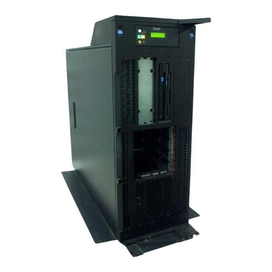
Note: This is the preferred method of loading online AIX diagnostics from the boot hard disk. System Locations The locations listed in this section can be used to help identify a component of the system. Model 275 Front View 1 Operator Panel 2 Slimline Media Bay 3 Slimline Media Bay 4 SCSI Media-Device Bay... -
Page 26: Rear View
Rear View 1 Parallel Connector 9 Mouse 2 Keyboard 10 1 Gb Ethernet Connector 3 Serial Connector 2 11 10/100 Gb Ethernet Connector 4 Serial Connector 3 12 Reserved 5 Test Connector (For Manufacturing 13 Reserved Use Only) 6 Serial Connector 1 14 Primary Power Supply V2 Receptacle 7 PCI-X Slot Access 15 Redundant Power Supply V1... -
Page 27: Power Supply Locations
Power Supply Locations Each power supply has three LEDs. The amber LED on the power supply indicates a problem with the power supply. If a power supply is diagnosed with a cooling problem, the entire power supply must be replaced. 1 Primary Power Supply V2 4 System Unit (In Service Position) 2 Redundant Power Supply V1... -
Page 28: Fan Locations
Fan Locations The following illustration identifies the system cooling fans. Each fan has one green LED and one amber LED located on top of the fan. A lit amber LED indicates that the fan is not operating correctly. 1 Cooling Fan 1 3 Cooling Fan 3 2 Cooling Fan 2 4 System Unit (In Service Position) -
Page 29: System Backplane Locations
System Backplane Locations The following illustration of the system backplane identifies the primary connectors used in your system. V3 V2 P1 P4 J0B J1B 1 Media Backplane 15 2.5V Voltage Regulator Module (V2) 2 Memory DIMM 5, J0A 16 (Hardware Management Console) 3 Memory DIMM 6, J0B 17 Primary Power Supply V2 4 Memory DIMM 7, J1A... -
Page 30: Pci-X Slot Locations
PCI-X Slot Locations Six PCI-X slots are available. Slots 1, 4, 5, and 6 are 64-bit capable at 133 MHz, 3.3 volts. Slots 2 and 3 are 32-bit capable at 66 MHz, 3.3 volts. All slots have hot-swap capabilities. The slots are numbered on the rear of the chassis from left to right, 1 through 6. -
Page 31: Memory Dimm Locations
Memory DIMM Locations The memory DIMMs used in the system are located on the system backplane. Your system contains eight memory DIMM slots. Associated with each memory DIMM slot is an LED, which is located on the edge of the system backplane. A lit LED indicates a problem with a specific memory DIMM. For more information on the locations of the system LEDs, go to “System LED Locations”... - Page 32 J3B (U0.1-P1-M1) J3A (U0.1-P1-M2) J2B (U0.1-P1-M3) J2A (U0.1-P1-M4) J0A (U0.1-P1-M5) J0B (U0.1-P1-M6) J1A (U0.1-P1-M7) J1B (U0.1-P1-M8) V3 V2 P1 P4 J0B J1B Number Description Location Code Memory slot 1 (J3B) U0.1-P1-M1 Memory slot 2 (J3A) U0.1-P1-M2 Memory slot 3 (J2B) U0.1-P1-M3 Memory slot 4 (J2A) U0.1-P1-M4...
-
Page 33: Operator Panel Component Locations
Operator Panel Component Locations The following illustration shows the component location on the operator panel. Number Component Name Component Description Operator Panel Display Displays current status of system startup, or diagnostic information in the event of a hardware problem. Attention LED Normal State - LED is off System Reset Button Resets the system... -
Page 34: Scsi Ids And Bay Locations
SCSI IDs and Bay Locations The following figure shows the SCSI bay locations for the Model 275. Index Drive Name SCSI ID Operator Panel Diskette Drive (U0.1-P1-X1/Q6-A1, for optical drive) or IDE Optical Drive IDE DVD-ROM (Default) IDE (Non-SCSI) (U0.1-P1-X1/Q6-A0) Tape Drive (Optional) SCSI ID 0 SCSI DVD-RAM (Optional) -
Page 35: System Led Locations
System LED Locations The following illustration shows the system LED locations for the Model 275. Grey dots represent amber LEDs and black dots represent green LEDs. Front View Rear View Top View = Green LED = Amber LED 1 Disk Drive LEDs 7 Power Supply LEDs 2 Power LED 8 Service Processor Assembly LED... -
Page 36: System Logic Flow
System Logic Flow The following diagram is a detailed representation of the system’s logic flow: Dual Chip Module DIMM D I M M SMI-E DIMM DIMM core core L3 Cache Main Data Unit JTAG Store Async 1.5MB L2 DIMM Cntl Intfc 8 MB DIMM... -
Page 37: Location Codes
Location Codes Note: When the system is running under the Linux operating system no Linux location codes exist, but physical location codes might display in the Linux error logs. This system unit uses physical location codes in conjunction with AIX location codes to provide mapping of the failing field replaceable units. - Page 38 For PCI adapters where x is equal to or greater than 1. The x and y are characters in the range of 0-9, A-H, J-N, P-Z (O, I, and lowercase are omitted) and are equal to the parent bus’s ’ibm, aix-location’ open firmware property.
-
Page 39: Multiple Fru Callout Instructions
Where AB-CD-EF are the same as non-SCSI devices. G defines the control unit address of the device. Values of 0 to 15 are valid. H defines the logical unit address of the device. Values of 0 to 255 are valid. A bus location code is also generated as ’00-XXXXXXXX’... - Page 40 v I/O adapter identify LED v DASD identify LED The identify LEDs are arranged hierarchically with the FRU identify LED at the bottom of the hierarchy, followed by the corresponding system unit or I/O drawer identify LED to locate the failing FRU more easily. Any identify LED in the system may be flashed when the system is in the failed state with power on by using the service processor ″LED Control Menu″...
-
Page 41: Mapping Aix And Physical Location Codes
Mapping AIX and Physical Location Codes Note: AIX location codes are not available when using the Linux operating system. Use the following illustration to help you map a location code to its connector on the system backplane. Chapter 1. Reference Information... - Page 42 Use the following illustration to help you map a location code to its connector on the rear of the system. Physical Location Location Codes Codes U0.1-P1/Q1 01-S1 U0.1-P1-X1/S1 01-S3 U0.1-P1-X1/S3 01-S2 U0.1-P1-X1/S2 01-R1 U0.1-P1-X1/R1 01-K1-00 U0.1-P1-X1/K1 U0.1-P1-X1/O1 01-K1-01 U0.1-P1-X1/Q4 U0.1-P1-X1/Q5 U0.1-P1/Q2 U0.1-P1/Q3 U0.1-P1-X1/S4...
-
Page 43: Aix And Physical Location Code Table
AIX and Physical Location Code Table Note: AIX location codes are not available when using the LINUX operating system. The following table contains AIX and physical location codes for the IntelliStation POWER 9114 Model 275 Component Name Physical Location Code AIX Location Code System Unit Backplane (Reserved) - Page 44 Component Name Physical Location Code AIX Location Code (Reserved) U0.1-P1-X1/S4 (Reserved) U0.1-P1-X1/S5 SPCN Connector1 (SPCN Port0) U0.1-P1-X1/Q4 SPCN Connector2 (SPCN Port1) U0.1-P1-X1/Q5 Keyboard Port U0.1-P1-X1/K1 01-K1-00 Keyboard U0.1-P1-X1/K1-K1 01-K1-00-00 Mouse Port U0.1-P1-X1/O1 01-K1-01 Mouse U0.1-P1-X1/O1-O1 01-K1-01-00 Ethernet #1 Controller U0.1-P1/E1 1L-08 Ethernet #2 Controller 1Gb U0.1-P1/E2...
- Page 45 Component Name Physical Location Code AIX Location Code System Cooling Fan 1 U0.1-F1 System Cooling Fan 2 U0.1-F2 System Cooling Fan 3 U0.1-F3 Operator Panel Operator panel U0.1-L1 System VPD module U0.1-L1-N1 Temperature Sensor (on Operator U0.1-L1 Panel) Time-of-Day Clock (TOD) U0.1-P1-X1 Power Supply Power supply V1 (Redundant)
-
Page 46: System Cables
System Cables The following diagrams show the internal cable routing for the Model 275. System Chassis Media Bay Chassis Operator Panel Cable Operator Panel Fan Tray Assembly Cable Fan Tray Assembly IntelliStation POWER 9114 Model 275 Service Guide... -
Page 47: Specifications
Specifications This section contains system specifications for the Model 275. Dimensions Height 535.0 mm (21.1 in.) Width 190.0 mm (7.5 in.) Depth 685.0 mm (27.0 in.) Weight Minimum configuration 32.0 kg (70.5 lbs.) Maximum configuration 43.1 kg (94.8 lbs.) Electrical Power source loading (typical in kVA) 0.31 Power source loading (max. -
Page 48: External Ac Power Cables
External AC Power Cables To avoid electrical shock, a power cable with a grounded attachment plug is provided. Use only properly grounded outlets. Power cables used in the United States and Canada are listed by Underwriter’s Laboratories (UL) and certified by the Canadian Standards Association (CSA). These power cords consist of the following: v Electrical cables, Type SVT or SJT. -
Page 49: Service Inspection Guide
Service Inspection Guide Perform a service inspection on the system when: v The system is inspected for a maintenance agreement. v Service is requested and service has not recently been performed. v An alterations and attachments review is performed. v Changes have been made to the equipment that may affect the safe operation of the equipment. v External devices with their own power cables have those cables attached. - Page 50 IntelliStation POWER 9114 Model 275 Service Guide...
-
Page 51: Chapter 2. Diagnostic Overview
Chapter 2. Diagnostic Overview The system uses an integrated set of software diagnostic procedures to help isolate failing components and system maintenance. This book, along with the RS/6000 Eserver pSeries Diagnostic Information for Multiple Bus Systems, is the basis of the diagnostic procedures for the system. In particular, Chapter 4, “Checkpoints,”... -
Page 52: System Leds
The Minimum Configuration MAP is used to locate defective components not found by normal diagnostics or error-isolation methods. This MAP provides a systematic method of isolation to the failing item. System LEDs LEDs provide a means to identify components in your system. For more information about these LEDs, see Chapter 11, “Component and Attention LEDs,”... -
Page 53: Fru Isolation
codes may also be shown on the operator panel display during this time. AIX progress codes and location codes will not appear if the LINUX operating system is booting. Error Codes If a fault is detected, an 8-digit error code is displayed in the operator panel display. A location code may be displayed at the same time on the second line. -
Page 54: Service Agent For The Model 275
v Boot to the open firmware prompt. See the “System Power Control Menu” on page 202 for instructions on setting up the boot mode to enable the boot to the open firmware prompt. To display a menu that will allow you to turn on the desired FRU identify LED, type FRU-LED-MENU on the command line. Service Agent for the Model 275 Service support for the Model 275 can be enhanced through the use of the service agent application. -
Page 55: Service Agent
A modem is required for enabling automated problem reporting to the IBM service center. Configuration files for several types of modems are included as part of the service agent package. Refer to “Modem Configuration Menu”... -
Page 56: Accessing System Log Error Information
Accessing System Log Error Information Note: The system attention LED can be reset by following the procedures described in “Resetting the System Attention LED.” When an error is detected by the system, information about the error is stored in error logs. The following sections explain how to access the logs that are available on a system. -
Page 57: Resetting The Led When A System Is Running Linux
Resetting the LED when a System is Running Linux The system must be powered off to access the service processor menus. From the service processor main menu, do the following: 1. Select System Information Menu. 2. Select LED Control Menu. 3. - Page 58 IntelliStation POWER 9114 Model 275 Service Guide...
-
Page 59: Chapter 3. Maintenance Analysis Procedures (Maps)
Chapter 3. Maintenance Analysis Procedures (MAPs) This chapter contains Maintenance Analysis Procedures (MAPs) for the Model 275. Note: HMC configurations and CD-ROM drives are not supported on this model. The diagnostics CD-ROM is placed in the supported DVD-ROM drive. Responses to questions referring to HMC should be ″no.″... - Page 60 The following table is used to help identify the types of error data in this guide. Number of Digits in Error Code Error Code Name in this Service Guide Contains # Menu Goal Contains - (hyphen) Does not contain # or - Does not contain # or - Error Code Does not contain # or -...
-
Page 61: Quick Entry Map
Quick Entry MAP Quick Entry MAP Table of Contents Problem Description Page No. Service actions The system attention LED on the operator panel is on. OK does not appear in the operator panel display before pressing the power-on button. Other symptoms appear in the operator panel display or LEDs before the power-on button is pressed. - Page 62 Symptom Action Service Actions You have parts to exchange or a corrective action to 1. Go to Chapter 9, “Removal and Replacement perform. Procedures,” on page 243. 2. Go to ″MAP 0410: Repair Checkout″ in the RS/6000 Eserver pSeries Diagnostic Information for Multiple Bus Systems.
- Page 63 System stops with a 4-digit number displayed The system stops with a 4-digit number displayed that does Go to “Checkpoint and Error Code Index” on page not begin with 0 or 2. 134.. If you do not find the error code there, go to the Fast Path MAP in the RS/6000 Eserver pSeries Diagnostic Information for Multiple Bus Systems.
- Page 64 Go to the Fast Path MAP in the RS/6000 Eserver An 888 sequence is displayed in the operator panel display. pSeries Diagnostic Information for Multiple Bus Systems. Other Symptoms or Problems The operator panel displays OK and the fans are off. The service processor is ready.
- Page 65 No codes are displayed on the operator panel within a few Reseat the operator panel cable. If the problem is not seconds of turning on the system. The operator panel is resolved, replace in the following order: blank before the system is powered on. 1.
- Page 66 The System Management Services menu is displayed. If you are loading diagnostics from the CD-ROM, you may not have pressed the correct key when you were trying to indicate a service mode IPL of the diagnostic programs. If this is the case, start again at the beginning of this step.
-
Page 67: Map 1020: Problem Determination
MAP 1020: Problem Determination Purpose of This MAP Use this MAP to get an error code if you were not provided one by the customer or you are unable to load diagnostics. If you are able to load the diagnostics, go to MAP 0020 in the RS/6000 Eserver pSeries Diagnostic Information for Multiple Bus Systems. - Page 68 Another feature that could disrupt a service action by powering on the system is an AIX function called timed power-on. This function is not available when using the Linux operating system. For more information about timed power-on, see “System Power-On Methods” on page 215. Be prepared to record code numbers and use those numbers in the course of analyzing a problem.
- Page 69 Symptom Action The system stopped and a code is displayed on the Go to the “Quick Entry MAP” on page 43. operator panel. The system stops with a prompt to enter a password. Enter the password. You cannot continue until a correct password has been entered.
- Page 70 Symptom Action The system stopped. A POST indicator is displayed on If the POST indicator represents: the system console and an eight-digit error code is not 1. Memory, go to “MAP 1240: Memory Problem displayed. Resolution” on page 55. 2. Keyboard a.
- Page 71 Symptom Action The System Management Services menu is displayed. If you are loading diagnostics from the CD-ROM, you may not have pressed the correct key when you were trying to indicate a service mode IPL of the diagnostic programs. If this is the case, start again at the beginning of this step.
- Page 72 Keyboard Type Action Type 106 keyboard. (Identified by the Japanese v Replace the type 106 keyboard. characters.) v Replace the service processor, location: U0.1-P1-X1. (See notes on page 41.) ASCII terminal keyboard Go to the documentation for this type of ASCII terminal and continue with problem determination.
-
Page 73: Map 1240: Memory Problem Resolution
MAP 1240: Memory Problem Resolution Note: The firmware or error code that sent you here could be one of the following: v Service Processor Checkpoints 910B, 910C, 910E or 95xx v Firmware Checkpoints E134 or E701 v System Power Control Network Error Code 1011840C v Firmware Error Codes 25Cyy001, 25Cyy002, 25B00001 or 25B00004 v Service Processor Error Codes 406x001x, 406x010x, 406x013x, 406x0CA6 or 450x30xx v Common Firmware Error Codes B1xx466x... -
Page 74: General Memory Information
General Memory Information Be sure to unplug the power cables before removing or installing memory DIMMs to avoid damage to them. Memory DIMMs must be installed in matched (size and speed) quads. Refer to “Memory DIMMs” on page 293 for labeling of the system backplane and instructions on memory DIMM removal and installation. Do not, however, replace the covers as directed while troubleshooting this problem. - Page 75 Step 1240-2 1. Turn off the power. Remove the power cord. 2. Remove one quad of DIMMs. Record the positions of the DIMMs as they are removed. When instructed to reinstall the DIMMs, install them back into the same slots from which they were removed. 3.
- Page 76 Are any DIMMs deconfigured or does the error code recorded in “Step 1240-1” on page 56 still appear? Replace the system planar. Enable memory repeat gard if necessary. Go to ″MAP 0410: Repair Checkout″ in the RS/6000 Eserver pSeries Diagnostic Information for Multiple Bus Systems.
- Page 77 Step 1240-6 Note: If only one quad of DIMMs is on the system planar, you must have at least one replacement DIMM of the same size and speed as the DIMMs that are on the system planar. If there were two quads of DIMMs on the system planar, but they are not the same size, you must have at least one replacement DIMM of the same size and speed as the DIMMs in the quad that is failing.
-
Page 78: Map 1320: Service Focal Point
MAP 1320: Service Focal Point These procedures define the steps to take when servicing a machine that is equipped with Service Focal Point (SFP). You might also be directed to these procedures if the system is running Linux as its only operating system. -
Page 79: Map 1321: Quick Entry Map For Systems With Service Focal Point
MAP 1321: Quick Entry MAP for Systems with Service Focal Point Notes: 1. If you are working on a system that is managed by an HMC, the term service action event is synonymous with serviceable event in this MAP. 2. If you are working on a system that is managed by an HMC, some steps in this MAP may ask you to open the details of the service action event and obtain error codes and FRU location codes. - Page 80 Go to “Step 1321-14.” Go to “Step 1321-8.” Step 1321-8 From the list of open service action events with FRUs reported, examine the details of each service action event and record the error code. Step 1321-9 Examine the list of error codes you obtained from “Step 1321-8” and look for any of the form 4xxB xxxx, A0D-34x, or A1D-34x.
- Page 81 Go to “Step 1321-16” on page 64. Chapter 3. Maintenance Analysis Procedures (MAPs)
- Page 82 Step 1321-16 Examine the details of the ten most-recently closed service action events. Are there any error codes or symptoms in the ten latest closed service action events that are the same as the error code or symptom recorded in “Step 1321-1” on page 61? Go to the table in “Entry MAP”...
- Page 83 Step 1321-23 Is Linux usable in any partition with Linux installed? Go to “Step 1321-30” on page 67. Go to “Step 1321-24.” Attention: “Step 1321-24” through “Step 1321-36” on page 68 must be performed on a partition running the Linux operating system. Step 1321-24 If your system is functional, examine the Linux system log by logging in to the system as the root user and entering the following command:...
- Page 84 Step 1321-26 Examine the Linux boot (IPL) log by logging in to the system as the root user and entering the following command: cat /var/log/boot.msg |grep RTAS |more Linux boot (IPL) error messages are logged into the boot.msg file under /var/log. The following is an example of the Linux boot error log.
- Page 85 Step 1321-29 Record any extended data found in the Linux system log in Step 1321-24 or the Linux boot (IPL) log in Step 1321-26. Be sure to record word 13. Note: The line(s) in the Linux extended data that begin with ″<4>RTAS: Log Debug: 04″ contain the error code listed in the next 8 hex characters.
- Page 86 Step 1321-34 Reboot the system and and bring all partitions to the login prompt. If Linux is not usable in all partitions, go to “Step 1321-38” on page 69. Step 1321-35 Use the lscfg command to list all resources assigned to all partitions. Record the adapter and the partition for each resource.
- Page 87 7. If the device adapter resides in the CEC, replace the I/O riser card, or the CEC backplane where the device adapter is located. 8. Call service support. Do not go to “Step 1321-34” on page 68. Step 1321-38 Does the system appear to stop or hang before reaching the login prompt or did you record any problems with resources in “Step 1321-36”...
- Page 88 Step 1321-43 Were any other symptoms recorded in step 1321-1? Call support. Go to the “Quick Entry MAP” on page 43 with each symptom you have recorded. Perform the indicated actions for all recorded symptoms, one at a time, until the problem has been corrected. If all recorded symptoms have been processed and the problem has not been corrected, call support.
-
Page 89: Map 1322: End Of Call Map For Systems With Service Focal Point
MAP 1322: End of Call MAP for Systems with Service Focal Point Note: If you are working on a system that not managed by an HMC go to ″MAP 0410: Repair Checkout″ in the RS/6000 Eserver pSeries Diagnostic Information for Multiple Bus Systems Step 1322-1 For future reference, record the SRC or symptom and the location code of the FRU you replaced. - Page 90 Step 1322-9 Is the FRU list identical (same FRUs, same number of FRUs, and same order of FRUs) to the FRU list of the error code recorded in “Step 1322-1” on page 71? Go to “Step 1322-10.” Go to “Step 1322-11.” Step 1322-10 The FRU list is different.
- Page 91 Step 1322-16 Remove all entries in the list of all partition(s) you recorded in “Step 1322-11” on page 72. If you are referred to the list of partition(s) obtained in “Step 1322-11” on page 72 in future steps, the list is empty. Go to “Step 1322-17.”...
- Page 92 Step 1322-27 Is the error class recorded in “Step 1322-6” on page 71 AIX? Go to “Step 1322-33.” Go to “Step 1322-28.” Step 1322-28 Perform the following steps for each entry in the list of all partition(s) you recorded in “Step 1322-11” on page 72, except the partition you were using to debug the original problem.
- Page 93 Step 1322-34 While processing all service action events, were you directed to “Step 1322-14” on page 72? If the system attention LED is still on, use the HMC to turn off the LED as described in “Resetting the LED when a System is Running AIX” on page 38. This completes the repair. Return the system to the customer.
-
Page 94: Map 1520: Power
MAP 1520: Power Notes: 1. This is not a start-of-call MAP. Use this Power MAP only if you have been directed here from another MAP, an SRN in the RS/6000 Eserver pSeries Diagnostic Information for Multiple Bus Systems, or an error code. -
Page 95: Fru Identify Leds
DANGER To prevent electrical shock hazard, disconnect all power cables from the electrical outlet before relocating the system. FRU Identify LEDs This system is configured with an arrangement of LEDs that help identify various components of the system. These include, but are not limited to: v Power subsystem FRUs v System unit FRUs v I/O adapter identify LED... -
Page 96: Map 1521: System Unit With Power Failure And No Error Codes
MAP 1521: System Unit With Power Failure and No Error Codes Step 1521-1 Do the following: 1. Place the deskside unit into a comfortable position for you to work on. 2. Remove the service access cover as described in “Removing the Service Access Cover” on page 249. You may have been directed to this MAP for one or more of the following reasons. - Page 97 Go to “Step 1521-6.” Correct the problem. Go to ″MAP 0410: Repair Checkout″ in the RS/6000 Eserver pSeries Diagnostic Information for Multiple Bus Systems. Step 1521-6 1. One of the following may be defective: v Power supplies v VRMs v Memory DIMMs v System backplane 2.
- Page 98 3. Record the slot numbers of all the adapters. Label and record the location of any cables attached to the adapters. Disconnect any cables attached to the adapters and remove all the adapters 4. Remove all but one quad of memory DIMMs from the system planar. 5.
- Page 99 3. Disk drives 4. Media bay devices 5. PCI adapters, lowest slot to highest slot 6. Fans Turn on the power after each part is installed or connected. If the system does not power on or the power LED located on the operator panel does not stay on, the most recently installed or connected part is causing the failure.
- Page 100 If the symptom did not change and all FRUs have been exchanged, go to “Step 1521-13.” If the symptom changed, check for loose cards, cables, and obvious problems. If you do not find a problem, go to the “Quick Entry MAP” on page 43 and follow the instructions for the new symptom.
- Page 101 Exchange the following FRUs in the order listed. 1. VRM at U0.1-P1-V1 2. VRM at U0.1-P1-V2 3. VRM at U0.1-P1-V3 4. System backplane Restart the system, and perform error log analysis. Do you get an SRN indicating a voltage sensor is out of range? The last FRU exchanged is defective.
-
Page 102: Map 1523: The Spcn Error Codes Table Directed You Here And The Error Code Is 1011 1B0X
MAP 1523: The SPCN Error Codes Table Directed You Here and the Error Code is 1011 1B0x A base system power supply is reporting a load fault. Note: Read the danger and caution notices under “Safety Notices” on page ix before continuing with this procedure. - Page 103 Replace base system power supply 2, location: U0.1-V2. This ends the procedure. Go to ″MAP 0410: Repair Checkout″ in the RS/6000 Eserver pSeries Diagnostic Information for Multiple Bus Systems. Step 1523-4 1. Turn off the power. 2. Reinstall base system power supply 2 that was removed in “Step 1523-2” on page 84. 3.
- Page 104 3. Reinstall one of the cards that was removed in “Step 1523-1” on page 84, in the sequence listed: a. One quad of DIMMs b. Other quad of DIMMs, if previously installed c. PCI adapter card(s) d. DASD device(s) e. Media bay device(s) 4.
-
Page 105: Map 1540: Problem Isolation Procedures
MAP 1540: Problem Isolation Procedures These procedures are used to locate problems in the processor subsystem, I/O subsystem(s) or rack. If a problem is detected, these procedures help you isolate the problem to a failing unit. FRU Identify LEDs This system is configured with an arrangement of LEDs that help identify various components of the system. - Page 106 Problem Isolation Procedures Symptom/Reference Code/Checkpoint Action E101, E102, E10A, E10B, E111, E120, E121, E122, Go to “MAP 1548: System Processor Problem Isolation” E130, E131, E132, E133, E134, E135, E138, E139, on page 90. E13A, E149, E14C, E191, E19A, E19B, E19D, E1A0, E1A1, E1A2, E1A3, E1A4, E1A5, E1A6, E1A7, E1A8, E1A9, E1AA, E1AB, E1AC, E1AD, E1AE, E1AF, E1B1, E1C4, E1C5, E1C6, E1D0, E1D3, E1D4, E1DB, E1F0,...
-
Page 107: Map 1541: Jtag Problem Isolation
MAP 1541: JTAG Problem Isolation Step 1541-1 Record the error code and location code(s) that sent you to this MAP. Step 1541-2 Turn off the power. Step 1541-3 Replace the following, if present, one at a time and in the order listed: v First location code item recorded, if any, “Step 1541-1.”... -
Page 108: Map 1548: System Processor Problem Isolation
MAP 1548: System Processor Problem Isolation Notes: 1. Be sure to unplug the power cords before removing or installing processor cards or the system backplane to avoid damage to it. 2. This MAP assumes that a CD-ROM drive is installed and connected to the integrated EIDE adapter, and a diagnostic CD-ROM disc is available. - Page 109 Step 1548-1 Ensure that the diagnostics and the operating system are shut down. 2. Turn on the power. 3. Insert the diagnostic CD-ROM into the CD-ROM drive. Note: If you cannot insert the diagnostic CD-ROM, go to “Step 1548-2.” 4. When the keyboard indicator is displayed: v on an ASCII terminal or hardware management console (HMC), press the number 5 key.
- Page 110 Go to “Step 1548-3.” Step 1548-3 Were there any memory DIMMs removed from the CEC backplane? Go to “Step 1548-8” on page 93. Go to “Step 1548-4.” Step 1548-4 1. Turn off the power, and remove the power cords. 2. Replug the memory DIMMs that were removed from the CEC backplane in “Step 1548-2” on page 91 in their original locations.
- Page 111 Does the system stop with code E1F2, E1F3, STBY or 20EE000B, 4BA00830 displayed on the operator panel? Reinstall the original FRU. Repeat the FRU replacement steps until the defective FRU is identified or all the FRUs have been exchanged. If the symptom did not change and all the FRUs have been exchanged, call service support for assistance.
- Page 112 If the symptom did not change and all the FRUs have been exchanged, call service support for assistance. If the symptom changed, check for loose cards, cables, and obvious problems. If you do not find a problem, go to the “Quick Entry MAP” on page 43 and follow the instructions for the new symptom.
- Page 113 8. Enter the appropriate password if you are prompted to do so. Is the Please define the System Console screen displayed? One of the FRUs remaining in the system unit is defective. Exchange the FRUs that have not been exchanged, in the following order: 1.
- Page 114 Step 1548-12 The system is working correctly with this configuration. One of the disk drives that you removed from the disk drive backplanes may be defective. 1. Make sure the diagnostic CD-ROM is inserted into the CD-ROM drive. 2. Turn off the power and remove the power cords. 3.
- Page 115 If the symptom did not change and all the FRUs have been exchanged, call service support for assistance. If the symptom has changed, check for loose cards, cables, and obvious problems. If you do not find a problem return, go to the “Quick Entry MAP” on page 43 and follow the instructions for the new symptom.
- Page 116 Is the Please define the System Console screen displayed? Go to “Step 1548-16.” Repeat this step until all of the FRUs (adapters) are installed. Go to ″MAP 0410: Repair Checkout″ in the RS/6000 Eserver pSeries Diagnostic Information for Multiple Bus Systems. Step 1548-16 The last FRU installed or one of its attached devices is probably defective.
- Page 117 Step 1548-17 1. Follow the instructions on the screen to select the system console. 2. When the DIAGNOSTIC OPERATING INSTRUCTIONS screen is displayed, press Enter. 3. Select Advanced Diagnostics Routines. 4. If the terminal type has not been defined, you must use the Initialize Terminal option on the FUNCTION SELECTION menu to initialize the AIX diagnostic environment before you can continue with the diagnostics.
- Page 118 Step 1548-19 Does the system have adapters or devices that require supplemental media? Go to “Step 1548-20.” Go to “Step 1548-21.” Step 1548-20 Consult the PCI adapter configuration documentation for your operating system to verify that all installed adapters are configured correctly. Go to ″MAP 0410: Repair Checkout″...
-
Page 119: Map 1549: Attention Problem Isolation
MAP 1549: Attention Problem Isolation Step 1549-1 Record the error code and the location code(s) that sent you to this MAP. Step 1549-2 Turn off the power. Step 1549-3 Examine the following table and locate the error code that sent you to this MAP to determine your next step. - Page 120 Step 1549-6 Did the system stop with the same error code as recorded in “Step 1549-1” on page 101? The card just replaced was defective. This ends the procedure. Return the system to its original configuration. Go to ″MAP 0410: Repair Checkout″ in the RS/6000 Eserver pSeries Diagnostic Information for Multiple Bus Systems.
-
Page 121: Map 154B: Insufficient Hardware Resources Problem Isolation
MAP 154B: Insufficient Hardware Resources Problem Isolation Step 154B-1 Record the error code, location code(s) and word 13 that sent you to this MAP. Step 154B-2 Turn off the power. Step 154B-3 Make sure the power is off on the base system drawer. Step 154B-4 Attention: Before replacing any parts examine the base system drawer for violation of any of the... - Page 122 Step 154B-8 Turn off the power. Step 154B-9 Ensure that the power is off on the base system drawer. Step 154B-10 Attention: Before replacing the processor backplane, call for support. Replace the processor backplane at U0.1-P1, if not already replaced. Step 154B-11 Turn on the power.
-
Page 123: Chapter 4. Checkpoints
Chapter 4. Checkpoints Checkpoints display on the media subsystem operator panel and the virtual terminal while the system is powering on and going through the initial program load (IPL). This chapter explains the IPL flow of the system and provides a table that lists checkpoints that you might see in the operator panel. IPL Flow The IPL process starts when ac power is connected to the system. -
Page 124: Service Processor Checkpoints
Checkpoints enable users and service personnel to know what the server is doing, with some detail, as it initializes. These checkpoints are not intended to be error indicators, but in some cases a server could hang at one of the checkpoints without displaying an 8-character error code. It is for these hang conditions, only, that any action should be taken with respect to checkpoints. - Page 125 Note: A spinning (or twirling) slash displays in the upper-right corner of the operator panel display while some checkpoints are being displayed. If the slash stops spinning, a hang condition is indicated. Table 1. Service Processor Checkpoints Checkpoint Description Action/ Possible Failing FRU 8000 Test of the service processor DRAM...
- Page 126 Table 1. Service Processor Checkpoints (continued) Checkpoint Description Action/ Possible Failing FRU 9030 Waiting for secondary thread See note 1 on page 112. acknowledgement 9033 I/O base initialization See note 1 on page 112. 9034 I2C initialization See note 1 on page 112. 9035 ISA initialization See note 1 on page 112.
- Page 127 Table 1. Service Processor Checkpoints (continued) Checkpoint Description Action/ Possible Failing FRU 9109 ABIST See note 1 on page 112. 910A Non-processor scan interface BATs and See note 1 on page 112. LBIST 910B Wire test See note 1 on page 112. 910C Initialize main storage (system memory) See note 1 on page 112.
- Page 128 Table 1. Service Processor Checkpoints (continued) Checkpoint Description Action/ Possible Failing FRU 9400 Service processor is requesting system See note 1 on page 112. flush 9410 Service processor is issuing request to start See note 1 on page 112. instruction execution 9411 Service processor is issuing request to stop See note 1 on page 112.
- Page 129 Table 1. Service Processor Checkpoints (continued) Checkpoint Description Action/ Possible Failing FRU 99FD Service processor receiving firmware See note 2 on page 112. update module Attention: This checkpoint may stay in the operator panel for some period of time during a firmware update or hypervisor dump with no indication of activity.
- Page 130 Table 1. Service Processor Checkpoints (continued) Checkpoint Description Action/ Possible Failing FRU A810-A8FF Scan log dump in progress Informational message. (See “Scan Log Dump Policy” on page 200.) The last two characters of the checkpoints will change as the scan log dump progresses.
- Page 131 a. Check the modem, modem cable, and serial port for loose or unconnected cables. Reset the service processor using the pinhole reset switch on the system’s operator panel. b. If the hang repeats, check with service support to see if there is a firmware update that fixes the problem.
-
Page 132: Firmware Checkpoints
Firmware Checkpoints Firmware uses checkpoints (progress codes) in the range of Exxx to EFFF. These checkpoints occur during system startup and can be useful in diagnosing certain problems. Service processor checkpoints are listed in “Service Processor Checkpoints” on page 106. If you have a checkpoint with no location code associated with it, see “Determining Location Code”... - Page 133 Table 2. Firmware Checkpoints (continued) Checkpoint Description Action/ Possible Failing FRU E139 Create node aliases and system aliases Go to “MAP 1540: Problem Isolation Procedures” on page 87. E13A Create packages node Go to “MAP 1540: Problem Isolation Procedures” on page 87. E140 Operating system load See “Boot Problems/Concerns”...
- Page 134 Table 2. Firmware Checkpoints (continued) Checkpoint Description Action/ Possible Failing FRU E174 Establishing host connection If the system is not connected to an active network, or if the target server is inaccessible (which can result from incorrect IP parameters being specified), the system still attempts to boot and because time-out durations are necessarily long to accommodate retries, the system...
- Page 135 Table 2. Firmware Checkpoints (continued) Checkpoint Description Action/ Possible Failing FRU E1A2 User requested boot using default service Go to “MAP 1540: Problem Isolation mode boot list via keyboard entry Procedures” on page 87. E1A3 User requested boot using customized Go to “MAP 1540: Problem Isolation service mode boot list via keyboard entry Procedures”...
- Page 136 Table 2. Firmware Checkpoints (continued) Checkpoint Description Action/ Possible Failing FRU E1B6 Probe for (ISA) keyboard Replace the service processor, Location: U0.1-P1-X1. E1BD Probe for (ISA) mouse Replace the service processor, Location: U0.1-P1-X1. E1C4 Build ISA timer chip node Go to “MAP 1540: Problem Isolation Procedures”...
- Page 137 Table 2. Firmware Checkpoints (continued) Checkpoint Description Action/ Possible Failing FRU E1F2 Power-on password prompt The prompt should be visible on the firmware console . If a console is attached but nothing is displayed on it, go to the “Quick Entry MAP”...
- Page 138 Table 2. Firmware Checkpoints (continued) Checkpoint Description Action/ Possible Failing FRU E1FD The operator panel alternates between the 1. If a location code is available, follow the code E1FD and another Exxx code, where actions listed for error code 21A0 00xx. Exxx is the point at which the error 2.
- Page 139 Table 2. Firmware Checkpoints (continued) Checkpoint Description Action/ Possible Failing FRU E506 Reset time base of processors 1. Check for system firmware updates. 2. Go to “MAP 1540: Problem Isolation Procedures” on page 87. E509 Begin configuring EADS 1. Check for system firmware updates. 2.
- Page 140 Table 2. Firmware Checkpoints (continued) Checkpoint Description Action/ Possible Failing FRU E581 Read the PCI bus configuration header. 1. Check for system firmware updates. 2. Go to “MAP 1540: Problem Isolation Procedures” on page 87. E582 EADS has been detected. 1.
- Page 141 Table 2. Firmware Checkpoints (continued) Checkpoint Description Action/ Possible Failing FRU E58F Set up EADS function registers 1. Check for system firmware updates. 2. Go to “MAP 1540: Problem Isolation Procedures” on page 87. E590 Set up EADS function registers 1.
- Page 142 Table 2. Firmware Checkpoints (continued) Checkpoint Description Action/ Possible Failing FRU E5E7 Save I/O hub information for RTAS and 1. Check for system firmware updates. open firmware 2. Go to “MAP 1540: Problem Isolation Procedures” on page 87. E5E8 Set up registers 1.
- Page 143 Table 2. Firmware Checkpoints (continued) Checkpoint Description Action/ Possible Failing FRU E702 Create processor card VPD. 1. Check for system firmware updates. 2. Call for support. E703 Create operator panel VPD. 1. Check for system firmware updates. 2. Call for support. E704 Create CEC VPD.
- Page 144 Table 2. Firmware Checkpoints (continued) Checkpoint Description Action/ Possible Failing FRU E843 Initializing RTAS/sensor interface 1. Check for system firmware updates. 2. Call service support. E844 Initializing RTAS/time-of-day clock interface 1. Check for system firmware updates. 2. Replace the CEC backplane Location: U0.1-P1.
- Page 145 Table 2. Firmware Checkpoints (continued) Checkpoint Description Action/ Possible Failing FRU E872 Initializing RTAS/error inject interface 1. Check for system firmware updates. 2. Call service support. E873 Initializing RTAS/error handling interface 1. Check for system firmware updates. 2. Call service support. E880 Initializing RTAS/debug interface 1.
-
Page 146: Boot Problems/Concerns
Boot Problems/Concerns Depending on the boot device, a checkpoint may be displayed on the operator panel for an extended period of time while the boot image is retrieved from the device. This is particularly true for tape and network boot attempts. If booting from CD-ROM or tape, watch for activity on the drive’s LED indicator. A blinking LED indicates that the loading of either the boot image or additional information required by the operating system being booted is still in progress. - Page 147 Step 3 Try to boot and run standalone diagnostics against the system, particularly against the intended boot device. If diagnostics do not boot successfully, and a SCSI boot failure (cannot boot from a SCSI attached device) is also occurring, go to “MAP 1548: System Processor Problem Isolation” on page 90. If diagnostics do not boot successfully, and a SCSI boot failure (cannot boot from a SCSI attached device) is not occurring: 1.
- Page 148 Step 4 It is possible that another installed adapter is causing the problem. Do the following: 1. Remove all installed adapters except the one the DVD-ROM drive is attached to and the one used for the console. 2. Try to boot the standalone diagnostics again. 3.
-
Page 149: Chapter 5. Error Code To Fru Index
Chapter 5. Error Code to FRU Index Note: Start your activity in this chapter by going to “Checkpoint and Error Code Index” on page 134. In this section, you may be asked to perform additional isolation procedures before looking up the actions for a 4-character checkpoint or 8-character error code. -
Page 150: Four-Character Checkpoints
Attempt to find the error code that originally sent you to the “Checkpoint and Error Code Index” on page 134. 1. If you can not find the error code in the service processor error log, start with the error code at the bottom of the list. -
Page 151: Replacing The Network Adapter
Replacing the Network Adapter If a network adapter is replaced, the network administrator must be notified so that the client IP addresses used by the system can be updated. In addition, the operating system configuration of the network controller may need to be changed in order to enable system startup. Also check to ensure that any client or server that accesses this system is updated. -
Page 152: Fru Identify Leds
If an HMC is attached, it may be used to activate and deactivate a FRU identify LED. For instructions on activating and deactivating a FRU identify LED, see the Service Focal Point chapter of the IBM Hardware Management Console for pSeries Installation and Operations Guide, order number SA38-0590. - Page 153 Checkpoint or Error What You Should Do Code 1xxx xxxx System Power Control Network (SPCN) Error Codes 1. There may be additional error codes and information in the service processor error log. The system must be powered off to examine the contents of the service processor error log.
- Page 154 Checkpoint or Error What You Should Do Code 4xxx xxxx Service Processor Error Codes 1. Is the system powered up? Go to step 2 below. Go to step 4 below. 2. Find the error code in the service processor error log and check the value of word 13. Go to 3 below.
- Page 155 Checkpoint or Error What You Should Do Code 8xxx Service Processor Checkpoints 9xxx Go to “Service Processor Checkpoints” on page 106 for more information on these Axxx checkpoints. Bxxx A1FD 000x The system has entered recovery mode. Go to “Recovery Mode” on page 220. B006 xxxx Common Firmware Error Codes B1xx xxxx...
-
Page 156: Operator Panel Error Codes
Operator Panel Error Codes Attention: If you replace FRUs or perform an action and the problem is still not corrected, go to “MAP 1540: Problem Isolation Procedures” on page 87 unless otherwise indicated in the tables. If you replace FRUs and the problem is corrected, go to ″MAP 0410: Repair Checkout″ in the RS/6000 Eserver pSeries Diagnostic Information for Multiple Bus Systems. -
Page 157: Spcn Error Codes
SPCN Error Codes Attention: If a power supply or fan is hot-swapped, wait five minutes, then recheck the operating system error log. If the system has to be shut down to replace a power supply or fan, reboot the system, wait five minutes after the operating system login prompt appears, then recheck the operating system error log. - Page 158 Table 4. SPCN Error Codes for the System Unit (continued) Error Code Description Action/ Possible Failing FRU 1011 2600 Pgood fault - power supply domain good Go to “MAP 1540: Problem Isolation Procedures” on page 87. 1011 2603 Pgood fault - power supply domain bad Go to “MAP 1540: Problem Isolation Procedures”...
- Page 159 Table 4. SPCN Error Codes for the System Unit (continued) Error Code Description Action/ Possible Failing FRU 1011 7620 System fan 2 fault Fan 2 Location: U0.1-F2 1011 7621 System fan 2 missing Fan 2 Location: U0.1-F2 1011 7626 Power supply 1 fan missing System drawer power supply 1 Location: U0.1-V1 1011 7630...
-
Page 160: Firmware Error Codes
Table 4. SPCN Error Codes for the System Unit (continued) Error Code Description Action/ Possible Failing FRU 1011 8413 Invalid processor VPD System backplane Location: U0.1-P1 1011 8414 Invalid processor VPD System backplane Location: U0.1-P1 1011 8415 Invalid processor VPD System backplane Location: U0.1-P1 1011 8416... - Page 161 Table 5. Firmware Error Codes. (continued) Error Code Description Action/ Possible Failing FRU 20D0 0011 Firmware RTAS attempt to allocate memory Contact your next level of support for assistance. failed. 20D0 0800 Firmware update failure Retry the flash update. 20D0 0801 System firmware update failure Retry the firmware update.
- Page 162 Table 5. Firmware Error Codes. (continued) Error Code Description Action/ Possible Failing FRU 20D0 0A0A Error initializing interface/interrupt access 1. Check for system firmware updates. Apply update if available. 2. Contact your next level of support for assistance. 20D0 0A0B Error initializing interface/OFDT access 1.
- Page 163 Table 5. Firmware Error Codes. (continued) Error Code Description Action/ Possible Failing FRU 20D0 0A15 Error initializing interface/error injection access 1. Check for system firmware updates. Apply update if available. 2. Contact your next level of support for assistance. 20D0 0A16 Error initializing interface/handling access 1.
- Page 164 Table 5. Firmware Error Codes. (continued) Error Code Description Action/ Possible Failing FRU 20D1 0003 Failed to send boot status 1. Check for system firmware updates. Apply update if available. 2. Contact your next level of support for assistance. 20D1 0004 Failed to locate service processor device tree 1.
- Page 165 Table 5. Firmware Error Codes. (continued) Error Code Description Action/ Possible Failing FRU 20D1 000D Function to get time-of-day failed. 1. Check for system firmware updates. Apply update if available. 2. Contact your next level of support for assistance. 20D1 000E Function to get time-of-day failed. 1.
- Page 166 Table 5. Firmware Error Codes. (continued) Error Code Description Action/ Possible Failing FRU 20E0 0009 Invalid password entered - system locked The password has been entered incorrectly 3 times. Turn off, then turn on the system unit, then enter the password correctly. 20EE 0003 IP parameter requires 3 dots ″.″...
- Page 167 Table 5. Firmware Error Codes. (continued) Error Code Description Action/ Possible Failing FRU 20EE 000C Description: Pointer to the operating system not found in non-volatile storage. Action: Values normally found in non-volatile storage that point to the location of an operating system were not found.
- Page 168 Table 5. Firmware Error Codes. (continued) Error Code Description Action/ Possible Failing FRU 20EE 0020 The environment variable ″boot-device″ exceeds If this error occurs during the installation of AIX by a ″NIM push″, the set_bootlist attribute may the allowed character limit. not have been set correctly on the NIM master.
- Page 169 Table 5. Firmware Error Codes. (continued) Error Code Description Action/ Possible Failing FRU 20FC 0030 Corrupted power, packaging, and cooling device 1. Check for system firmware updates. VPD format in the SPCN configuration table. 2. Replace the part specified by the location code.
- Page 170 Table 5. Firmware Error Codes. (continued) Error Code Description Action/ Possible Failing FRU 21A0 0002 SCSI DASD - test unit ready failed - sense data Before replacing any system components, refer available to the notes in error code 21A0 0001. 1.
- Page 171 Table 5. Firmware Error Codes. (continued) Error Code Description Action/ Possible Failing FRU 21EE 0001 Undetermined SCSI device type - test unit ready Before replacing any system components, refer failed - hardware error to the notes in error code 21A0 0001. 1.
- Page 172 Table 5. Firmware Error Codes. (continued) Error Code Description Action/ Possible Failing FRU 21F2 0003 SCSI read/write optical - send diagnostic failed- Before replacing any system components, refer sense data available to the notes in error code 21A0 0001. Replace the SCSI device. 21F2 0004 SCSI read/write optical - send diagnostic failed- Before replacing any system components, refer DevOfl cmd...
- Page 173 Table 5. Firmware Error Codes. (continued) Error Code Description Action/ Possible Failing FRU 25A8 0100 NVRAM data validation check failed. Turn off, then turn on system unit and retry the operation before replacing any system component. Refer to Action under error code 25A80xxx. 25A8 0201 Unable to expand target partition - saving Refer to Action under error code 25A80xxx.
- Page 174 Table 5. Firmware Error Codes. (continued) Error Code Description Action/ Possible Failing FRU 25B0 0001 No memory DIMMs detected. Go to “MAP 1240: Memory Problem Resolution” on page 55. 25B0 0004 Multiple memory DIMMs failed a memory test. Go to “MAP 1240: Memory Problem Resolution” on page 55.
- Page 175 Table 5. Firmware Error Codes. (continued) Error Code Description Action/ Possible Failing FRU 2602 0008 Description: PCI device Fcode evaluation error Action: 1. If the location code identifies a slot: a. Check for adapter firmware updates. Apply if available. b. Replace the adapter. c.
- Page 176 Table 5. Firmware Error Codes. (continued) Error Code Description Action/ Possible Failing FRU Power off the system. See “Removing a Non-Hot-Pluggable PCI Adapter” on page 253 and “Replacing or Installing a Non-Hot-Pluggable PCI Adapter” on page 255 for instructions on reseating the card. If reseating the adapter fixes the problem, go to ″MAP 410, Repair Checkout″...
- Page 177 Table 5. Firmware Error Codes. (continued) Error Code Description Action/ Possible Failing FRU The problem is associated with bridge ″y″ in I/O 2680 0Axy MX-PCI bridge BIST failure drawer ″x.″ Replace the I/O backplane in I/O drawer ″x.″ Location U0.x-P1 See “Determining Location Code”...
- Page 178 Table 5. Firmware Error Codes. (continued) Error Code Description Action/ Possible Failing FRU 2803 F003 Real-time-clock not updating - not correctable Replace the service processor (detected by hypervisor) Location: U0.1-P1-X1 2900 0002 Keyboard/mouse controller failed self-test Replace service processor Location: U0.1-P1-X1 29A0 0003 Keyboard not present/detected 1.
- Page 179 Table 5. Firmware Error Codes. (continued) Error Code Description Action/ Possible Failing FRU 2B20 8884 Unrecoverable processor subsystem error If Linux is the only operating system on the failing system, call service support. If AIX is available, and the system is powered down, replace the FRU indicated by the service processor error log entry.
- Page 180 Table 5. Firmware Error Codes. (continued) Error Code Description Action/ Possible Failing FRU 2BA0 0071 VPD data is corrupted for processor 1. Replace the service processor Location: U0.1-P1 2BA0 0073 Reserved Reserved 2BA0 0080 Service processor hardware reset request failure 1. Check for system firmware updates. Apply if available.
-
Page 181: Service Processor Error Codes
Service Processor Error Codes Attention: Follow the procedure defined in the “Checkpoint and Error Code Index” on page 134. If you replace FRUs or perform an action and the problem is still not corrected, go to “MAP 1548: System Processor Problem Isolation” on page 90 unless otherwise indicated in the tables. If you replace FRUs and the problem is corrected, go to ″MAP 0410: Repair Checkout″... - Page 182 Table 6. Service Processor Error Codes. (continued) Error Code Description Action/ Possible Failing FRU 406x 0A03 Reboot message (run-time array gard failure) for Array bit steering, which is a function in the processor 0. firmware, may be able to correct this problem without replacing hardware.
- Page 183 Table 6. Service Processor Error Codes. (continued) Error Code Description Action/ Possible Failing FRU 406x 0EA0 MOPS service processor code error. 1. Check for system firmware updates. 2. Call service support. 406x 0EA1 Operating system code on main processor 1. Check for operating system code updates. 2.
- Page 184 Table 6. Service Processor Error Codes. (continued) Error Code Description Action/ Possible Failing FRU 406x 0EBF Memory error 1. Reboot the system in slow mode to the SMS menus. See “Performing a Slow Boot” on page 131. Examine the service processor error log. If a system unit subsystem error (a 4xxx yyyy error) occurred during the slow boot calling out the memory, processors, L3...
- Page 185 Table 6. Service Processor Error Codes. (continued) Error Code Description Action/ Possible Failing FRU 4503 271C Description:System backplane with 2 processors fault: Action: This error code indicates that the processor repeat gard function has deconfigured a processor. Do the following: 1.
- Page 186 Table 6. Service Processor Error Codes. (continued) Error Code Description Action/ Possible Failing FRU 4503 30D3 Description: 1 GB DIMM fault Action: This error code indicates that the memory repeat gard function has deconfigured a quad of memory. Do the following: 1.
- Page 187 Table 6. Service Processor Error Codes. (continued) Error Code Description Action/ Possible Failing FRU 450x 271B System backplane with 1 processor fault Replace the system unit backplane Location: U0.1-P1 450x 271C System backplane with 2 processors fault Replace the system unit backplane Location: U0.1-P1 450x 30D1 256 MB DIMM Go to “MAP 1240: Memory Problem Resolution”...
-
Page 188: Memory Dimm Present Detect Bits (Pd-Bits)
Table 6. Service Processor Error Codes. (continued) Error Code Description Action/ Possible Failing FRU 4B23 271C Description: 2-way processor card fault Action: This error code indicates that the processor repeat gard function has deconfigured a processor. Do the following: 1. Go to the processor configuration/deconfiguration menu, located under the system information menu in the service processor menus. -
Page 189: Error Log Utility Procedure
Error Log Utility Procedure When the System Management Services menu appears, check the error log for any errors. Use the location code obtained from the SMS error log utility to identify the component the error is reported against. To obtain the location code from the error log utility do the following: 1. - Page 190 Table 9. Common Firmware Error Codes (continued) Error Code Description Action/ Possible Failing FRU B006 1404 Service processor firmware fault 1. Update system firmware 2. Service processor Location: U0.1-P1-X1 B006 1405 Service processor firmware fault 1. Update system firmware 2. Service processor Location: U0.1-P1-X1 B006 1406 Service processor program error 1.
- Page 191 Table 9. Common Firmware Error Codes (continued) Error Code Description Action/ Possible Failing FRU B10F 1381 Service processor flash error 1. Update system firmware 2. Service processor Location: U0.1-P1-X1 B10F 1384 Service processor failure Service processor Location: U0.1-P1-X1 B10F 1387 Service processor failure Service processor Location: U0.1-P1-X1 B10F 1400 Service processor failure...
- Page 192 Table 9. Common Firmware Error Codes (continued) Error Code Description Action/ Possible Failing FRU B1xx 4602 Hardware failure 1. Was this error code logged just after the system crashed? Go to step 3. Go to step 2. 2. Examine the service processor error log. Look for a 4xxx yyyy error that calls out FRU(s) in the system unit whose timestamp just precedes the B1xx 4602 error.
- Page 193 Table 9. Common Firmware Error Codes (continued) Error Code Description Action/ Possible Failing FRU B1xx 4611 Service processor failure System backplane Location: U0.1-P1 B1xx 4620 Modem configuration failure 1. Check modem configuration files 2. Check for system firmware update 3. Modem 4.
- Page 194 Table 9. Common Firmware Error Codes (continued) Error Code Description Action/ Possible Failing FRU B1xx 4633 System power control (SPCN) network failure This error code may be informational, or it may indicate a failure in the SPCN firmware update. Before changing any parts, examine word 13 in the service processor error log entry, or bytes 68 and 69 in the AIX error log entry.
- Page 195 Table 9. Common Firmware Error Codes (continued) Error Code Description Action/ Possible Failing FRU B1xx 4647 Write TM field in system VPD Replace the operator panel, location: U0.1-L1. Do not attempt to swap the VPD module from the old operator panel onto the new operator panel.
- Page 196 Table 9. Common Firmware Error Codes (continued) Error Code Description Action/ Possible Failing FRU B1xx 4672 Critical temperature in I/O subsystem 1. Check ambient temperature. 2. Check air supply to fans. 3. Check fans for proper installation and operation. 4. Check for unsupported cards (which may be too hot) 5.
- Page 197 Table 9. Common Firmware Error Codes (continued) Error Code Description Action/ Possible Failing FRU B1xx 4693 Service processor firmware error 1. Check for system firmware updates. 2. Call service support. B1xx 4694 System processor firmware failure 1. Check for system firmware updates. 2.
- Page 198 Table 9. Common Firmware Error Codes (continued) Error Code Description Action/ Possible Failing FRU B1xx 4699 Service processor firmware: This is usually an indication of a problem in the communication path between the HMC and the service processor. It may only be an informational message. If the managed system is down, go to the service processor error log and find the error log entry containing B1xx 4699.
- Page 199 Table 9. Common Firmware Error Codes (continued) Error Code Description Action/ Possible Failing FRU B1xx 4699 (Continued from the previous page.) (continued) A806: This indicates a loss of the surveillance heartbeat between the HMC and the service processor. Actions: 1. Make sure that the HMC is booted and operational. 2.
-
Page 200: Scan Log Dump Progress Codes
Table 9. Common Firmware Error Codes (continued) Error Code Description Action/ Possible Failing FRU B1FD 0013 A firmware update has failed because the Reset the service processor (by activating the update image is invalid. The update was stopped pinhole reset switch or by disconnecting, then before any changes were made to the currently reconnecting power). -
Page 201: Problem Determination Generated Error Codes
Problem Determination Generated Error Codes Table 10. Problem Determination Generated Error Codes Error Code Description Action/ Possible Failing FRU M0BT 0000 The system hung during speaker POST. This Go to “MAP 1540: Problem Isolation Procedures” error code is generated by the customer on page 87. - Page 202 Table 10. Problem Determination Generated Error Codes (continued) Error Code Description Action/ Possible Failing FRU M0SC SI01 Unable to load diagnostics. This error code is Go to “Boot Problems/Concerns” on page 128. generated by the customer performing “Problem Determination” in the IntelliStation POWER 9114 Model 275 User’s Guide.
-
Page 203: Chapter 6. Using The Online And Standalone Diagnostics
Chapter 6. Using the Online and Standalone Diagnostics The AIX diagnostics consist of online diagnostics and standalone diagnostics. Attention: The AIX operating system must be installed in order to run online diagnostics. If the AIX operating system is not installed, use the standalone diagnostic procedures. Online diagnostics, when they are installed, reside with AIX in the file system. -
Page 204: Online Diagnostics Modes Of Operation
Online Diagnostics Modes of Operation Note: Online diagnostics can only be run if AIX is installed. The online diagnostics can be run in the following modes: v Service Mode v Concurrent Mode v Maintenance Mode Service Mode Service mode provides the most complete checkout of the system resources. This mode also requires that no other programs are running. -
Page 205: Concurrent Mode
If all types of devices in the boot list have been polled without finding a bootable image, the system restarts. This action gives the user the opportunity to start the System Management Services (by pressing the number 1 key on a directly attached keyboard or the number 1 on an ASCII terminal) before the system attempts to boot again. -
Page 206: Maintenance Mode
The diag command is then used to invoke the diagnostic controller so you can run the diagnostics. After the diagnostic controller is loaded, follow the normal diagnostic instructions. Documentation for the AIX operating system is available from the IBM Eserver pSeries Information Center at http://publib16.boulder.ibm.com/pseries/en_US/infocenter/base. Select AIX documentation. The AIX Documentation CD contains the base set of publications for the operating system, including system-management and end-user documentation. -
Page 207: Standalone Diagnostic Operation
Standalone Diagnostic Operation Use standalone diagnostics to test the system when the online diagnostics are not installed and as a method of testing the disk drives that cannot be tested by the online diagnostics. Note: The DVD-ROM drive and the SCSI controller that controls it cannot be tested by the standalone diagnostics. -
Page 208: Nim Server Configuration
Registering a client on the NIM server v Enabling a client to run diagnostics from the NIM server Documentation for the AIX operating system is available from the IBM Eserver pSeries Information Center at http://publib16.boulder.ibm.com/pseries/en_US/infocenter/base. Select AIX documentation. The AIX Documentation CD contains the base set of publications for the operating system, including system-management and end-user documentation. -
Page 209: Booting Standalone Diagnostics From The Nim Server
Booting Standalone Diagnostics from the NIM Server To run standalone diagnostics on a client from the NIM server, do the following: 1. Boot to the SMS Main screen. 2. Select Select Boot Options. 3. Select Install or Boot a Device. 4. - Page 210 IntelliStation POWER 9114 Model 275 Service Guide...
-
Page 211: Chapter 7. Using The Service Processor
Chapter 7. Using the Service Processor The service processor runs on its own power boundary and continually monitors hardware attributes and the environmental conditions within the system. The service processor is controlled by firmware and does not require the operating system to be operational to perform its tasks. The service processor menus allow you to configure service processor options, as well as enable and disable functions. -
Page 212: Menu Inactivity
The service aid, Save or Restore Hardware Management Policies, can be used to save your settings after initial setup or whenever the settings must be changed for system operation purposes. It is strongly recommended that you use this service aid for backing up service processor settings to protect the usefulness of the service processor and the availability of the system. -
Page 213: General User Menu
General User Menu The menu options presented to the general user are a subset of the options available to the privileged user. The user must know the general-access password, if one is set, to access this menu. GENERAL USER MENU 1. -
Page 214: Main Menu
Note: The information under the Service Processor Firmware heading in the following Main Menu illustration is example information only. Service Processor Firmware VERSION: 1F030521 Copyright 2003 IBM Corporation SYSTEM NAME MAIN MENU 1. Service Processor Setup Menu 2. System Power Control Menu 3. -
Page 215: Service Processor Setup Menu
Service Processor Setup Menu The following Service Processor Setup Menu is accessed from the Main Menu: SERVICE PROCESSOR SETUP MENU 1. Change Privileged Access Password 2. Change General Access Password 3. Enable/Disable Console Mirroring: Currently Enabled 4. Start Talk Mode 5. -
Page 216: Passwords
Passwords Passwords can be any combination of up to eight alphanumeric characters. You can enter longer passwords, but the entries are truncated to include only the first eight characters. The privileged-access password can be set from service processor menus or from System Management Services (SMS) utilities (see Chapter 8, “Using System Management Services,”... - Page 217 v Change Privileged-Access Password Set or change the privileged-access password. It provides the user with the capability to access all service processor functions. This password is usually used by the system administrator or root user. v Change General-Access Password Set or change the general-access password. It provides limited access to service processor menus, and is usually available to all users who are allowed to power on the system, especially remotely.
- Page 218 This option requires a diskette drive to be installed in the system. If this option is selected, and no diskette drive is present in the system, the service processor will indicate Not Supported on the screen. This option updates the system EPROMs. After entering Y to indicate that you want to continue, you are prompted to enter the update diskettes.
- Page 219 – Attempt to reboot. Scan Log Dump Setup Menu 1. Scan Log Dump Policy: Currently As Needed 2. Scan Log Dump Content: Currently As Requested 3. Immediate Dump 98. Return to Previous Menu 0> 1 Select from the following options: (As Needed=2, Always=3) Enter New Option: 0>...
-
Page 220: System Power Control Menu
4 = Minimum The dump will include the smallest amount of information possible (a minimum number of hardware scan log rings). The complete dump will take the longest time to finish; it may take as long as 1.5 hours on a fully configured system. - Page 221 RING INDICATE POWER-ON MENU 1. Ring indicate power-on : Currently Enabled 2. Number of rings: Currently 3 30. Refresh Modem Settings 98. Return to Previous Menu Ring indicate power-on is enabled by default on both serial port 1 (S1) and serial port 2 (S2). When ring indicate power-on is enabled, call-in is disabled.
- Page 222 The Use OS-Defined restart policy is set to Yes, and the operating system has no automatic restart policy. – Call-Out before restart (Enabled/Disabled) - If a restart is necessary due to a system fault, you can enable the service processor to call out and report the event. This option can be valuable if the number of these events becomes excessive, which might signal a bigger problem.
-
Page 223: System Information Menu
System Information Menu This menu provides access to system configuration information, error logs, system resources, and processor configuration. SYSTEM INFORMATION MENU 1. Read VPD Image from Last System Boot 2. Read Progress Indicators from Last System Boot 3. Read Service Processor Error Logs 4. - Page 224 v Read Service Processor Configuration Displays current service processor configuration. v Processor Configuration/Deconfiguration Menu Enable/Disable CPU Repeat Gard CPU repeat gard will automatically deconfigure a CPU during a system boot if a processor has failed BIST (built-in self-test), caused a machine check or check stop, or has reached a threshold of recoverable errors.
- Page 225 5. Non-repeat-gardable error. The resource may be reconfigured on the next boot. A status of 00 indicates that the CPU has not had any errors logged against it by the service processor. To enable or disable CPU repeat gard, use menu option 77. CPU repeat gard is enabled by default. If CPU repeat gard is disabled, processors that are in the ″deconfigured by system″...
- Page 226 MEMORY CONFIGURATION/DECONFIGURATION MENU 77. Enable/Disable Memory Repeat Gard: Currently Enabled 78. Runtime Recoverable Error Repeat Gard: Currently Disabled 1. Memory card 98. Return to Previous Menu After you select the memory card option by entering 1, a menu displays, allowing the selection of a memory DIMM.
- Page 227 To enable or disable runtime recoverable error repeat gard, use option 78 of the Memory Configuration/Deconfiguration Menu. The failure history of each DIMM is retained. If a DIMM with a history of failures is brought back online by disabling Repeat Gard, it remains online if it passes testing during the boot process. However, if Repeat Gard is enabled, the DIMM is taken offline again because of its history of failures.
-
Page 228: Language Selection Menu
040200010006041000010006d0e38501000604100002000000000006d0e385020006041000030006d0e 385030006158010000006154003180006101116000006101116010006158010010007158156a0000711 00001000000000000910120000000910120001 ***** Power Trace data End ***** (Press Return to Continue) v LED Indicator Menu This menu displays the state of the processor subsystem disturbance/system attention LED. Use this menu to toggle the attention/fault LED between identify (blinking) and off. Option 1 is only available when the system is in the error state (the CEC is powered on and the service processor menus are available). -
Page 229: Call-In/Call-Out Setup Menu
LANGUAGE SELECTION MENU 1. English 2. Francais 3. Deutsch 4. Italiano 5. Espanol 98. Return to Previous Menu 99. Exit from Menus 0> Note: Your virtual terminal window must support the ISO-8859 character set to correctly display languages other than English. Call-In/Call-Out Setup Menu Note: The information in this section regarding the configuring of serial ports, and modems attached to those serial ports, applies only to the serial ports (S1 and S2) on the system backplane (location... -
Page 230: Modem Configuration Menu
Modem Configuration Menu Note: This option applies only to a modem attached to serial port 1 (S1) or serial port 2 (S2) on the CEC backplane. The first two lines of the Modem Configuration Menu contain status of the current selections. Selections are made in the sections labeled Modem Ports and Modem Configuration File Name. -
Page 231: Serial Port Speed Setup Menu
Serial Port Speed Setup Menu This menu allows you to set serial port speed to enhance terminal performance or to accommodate modem capabilities. Serial Port Speed Setup Menu 1. Serial Port 1 Speed: Currently 9600 2. Serial Port 2 Speed: Currently 9600 98. -
Page 232: Call-Out Policy Setup Menu
v Customer Administration Center Telephone Number is the number of the System Administration Center computer (catcher) that receives problem calls from servers. Contact your system administrator for the correct telephone number to enter here. Until you have that number, leave this field unassigned. v Digital Pager Telephone Number is the number for a numeric pager carried by someone who responds to problem calls from your system. -
Page 233: Customer Account Setup Menu
Customer Account Setup Menu This menu allows users to enter information that is specific to their account. Customer Account Setup Menu 1. Customer Account Number: Currently Unassigned 2. Customer RETAIN Login userid: Currently Unassigned 3. Customer RETAIN login password: Currently Unassigned 98. -
Page 234: Service Processor Reboot/Restart Recovery
v Unattended start mode - refer to Enable/Disable Unattended Start Mode on page 202. The service processor can be enabled to recover from the loss of ac power (see Enable/Disable Unattended Power-On Mode in the SYSTEM POWER CONTROL MENU). When ac power is restored, the system returns to the power state at the time ac loss occurred. -
Page 235: Service Processor Reboot/Restart Policy Controls
processor parameter ″Use OS-Defined Restart Policy″ is yes (the default), the service processor takes over for AIX to reboot/restart after a hardware or surveillance failure. Service Processor Reboot/Restart Policy Controls The operating system’s automatic restart policy (see operating system documentation) indicates the operating system response to a system crash. -
Page 236: System Firmware Updates
Download the detailed instructions, as well as the latest flash images, from the following Web address: http://techsupport.services.ibm.com/server/mdownload2. Before doing a system firmware update, check the Web site for the latest code and images. Do not attempt a firmware update if you are unsure of the image you have, or of the procedure required for the update. -
Page 237: Determining The Level Of Firmware On The System
Note: This information may be superseded by information that is available on the following Web site. Always check the Web site for the latest images and instructions for checking the firmware level. The Web address is: http://www.rs6000.ibm.com/support/micro. The firmware level is denoted by vFyymmdd, where: v = version number v F = the system’s firmware designation... -
Page 238: Updating System Firmware From The Service Processor Menus
Attention: Do not overlook the periods (.) in the commands shown above. AIX commands are case-sensitive. Type them exactly as shown. If the system is running Linux, refer to the detailed instructions with the latest image that are provided on CORE or from the Web site You will be asked for confirmation to proceed with the firmware update and the required reboot. -
Page 239: Configuring And Deconfiguring Processors Or Memory
Notes: 1. If the wrong diskette is inserted at any time, or if the diskette is left in the drive after it has been read, B1FD 001F is displayed, indicating that the wrong diskette is in the drive. 2. If B1FD 001A is displayed at any time during the process, the service processor must be reset by activating the pinhole reset switch on the primary drawer operator panel. -
Page 240: Service Processor System Monitoring - Surveillance
Service Processor System Monitoring - Surveillance Surveillance is a function in which the service processor monitors the system, and the system monitors the service processor. This monitoring is accomplished by periodic samplings called heartbeats. Surveillance is available during the following phases: v System firmware bringup (automatic) v Operating system run-time (optional) Note: Operating system surveillance is disabled in partitioned systems. -
Page 241: Call-Out (Call-Home)
3. To call out before restart, set Call-out before restart to ENABLED from the Reboot/Restart Policy Setup menu. Note: Some modems, such as the IBM 7857-017, are not designed for the paging function. Although they can be used for paging, they will return an error message when they do not get the expected response from another modem. -
Page 242: Service Processor Error Log
1. Remote session is already in progress. 2. Remote user uses service processor menus to enable console mirroring, allowing both consoles to be active. v Local session first, then remote session added: 1. Local session is already in progress. 2. The service processor receives a call from the remote user. 3. -
Page 243: Lcd Progress Indicator Log
LCD Progress Indicator Log The following is an example of the LCD progress indicator log. It shows the types of entries that can appear in the log and is for example purposes only. The progress indicator codes are listed from top (latest) to bottom (oldest). LCD Progress Indicator Log B0FF 0539..17... -
Page 244: Service Processor Operational Phases
Service Processor Operational Phases This section provides a high-level flow of the phases of the service processor. SP Power Applied Pre-Standby Phase Standby Phase SP Menus Available Bring-Up Phase SMS Menus Available Run-time Phase Operating System Login Prompt Available Pre-Standby Phase This phase is entered when the system is connected to a power source. -
Page 245: Bring-Up Phase
The service processor menus are password-protected. Before you can access them, you need either the general user-password or privileged-user password. Service processor menus are available on ASCII terminals attached to the serial ports on the system, and on terminal emulators. Bring-Up Phase This phase is entered upon power-on, and exited upon loading of the operating system. - Page 246 IntelliStation POWER 9114 Model 275 Service Guide...
-
Page 247: Chapter 8. Using System Management Services
Chapter 8. Using System Management Services Use the system management services menus to view information about your system , and to perform tasks such as setting a password, changing the boot list, and setting the network parameters. Note: On some of the system management services (or service processor) screens, you will see the term LPAR, which is equivalent to the term logical partition. - Page 248 When there is more than one page of information to display, there are two additional navigation keys: Display the next page of the list. Display the previous page of the list. Note: The lowercase navigation key has the same effect as the uppercase key that is shown on the screen.
-
Page 249: Select Language
Select Language Note: Your TTY must support the ISO-8859 character set to properly display languages other than English. This option allows you to change the language used by the text-based System Management Services menus. SELECT LANGUAGE 1. English 2. Francais 3. -
Page 250: View Error Log
View Error Log Use this option to view or clear your system’s error log. A menu similar to the following displays when you select this option. Error Log Date Time Error Code Location Entry 1. 01/04/96 12:13:22 25A80011 00-00 Entry 2. no error logged 1. -
Page 251: Setup Remote Ipl (Initial Program Load)
NIC Adapters Device Slot Hardware Address 10/100 Mbps Ethernet PCI Adapt Integ: U0.1-P1/E1 00096baeac10 IBM 10/100/1000 Base-TX PCI Integ: U0.1-P1/E2 0009cbce0fde ------------------------------------------------------------------------------------------- Navigation keys: M = return to main menu ESC key = return to previous screen X = eXit System Management Services... - Page 252 Adapter Configuration 10/100 Mbps Ethernet PCI Adapter II: U0.1-P1/E1 1. Speed, Duplex 2. Spanning Tree Enabled 3. Protocol ------------------------------------------------------------------------------------------- Navigation keys: M = return to main menu ESC key = return to previous screen X = eXit System Management Services ------------------------------------------------------------------------------------------- Type the number of the menu item and press Enter or Select a Navigation key: _ Selecting the Speed, Duplex option allows you to set the interface speed at which the card will run at half...
-
Page 253: Change Scsi Settings
Protocol 10/100 Mbps Ethernet PCI Adapter II: U0.1-P1/E1 1. Standard <=== 2. IEEE802.3 ------------------------------------------------------------------------------------------- Navigation keys: M = return to main menu ESC key = return to previous screen X = eXit System Management Services ------------------------------------------------------------------------------------------- Type the number of the menu item and press Enter or Select a Navigation key: _ Select the ping test option from the network parameters menu to test an adapter’s network connection to a remote system. -
Page 254: Select Boot Options
Select Boot Options Use this menu to view and set various options regarding the installation devices and boot devices. 1. Select Install or Boot a Device 2. Select Boot Devices 3. Multiboot Startup ------------------------------------------------------------------------------------ Navigation keys: M = return to main menu ESC key = return to previous screen X = eXit System Management Services ------------------------------------------------------------------------------------... - Page 255 If option 1 is selected, the following menu is displayed: Select Device Type 1. Diskette 2. Tape 3. CD/DVD 4. IDE 5. Hard Drive 6. Network 7. None 8. List All Devices ------------------------------------------------------------------------------------ Navigation keys: M = return to main menu ESC key = return to previous screen X = eXit System Management Services ------------------------------------------------------------------------------------...
- Page 256 If List All Devices is selected, a menu similar to the following displays, depending on the devices that are installed in the system: Select Device Device Current Device Number Position Name SCSI 18200 MB Harddisk (loc=U0.1-P2/Z1-A8,0) SCSI 18200 MB Harddisk (loc=U0.1-P2/Z1-A9,0) SCSI 18200 MB Harddisk (loc=U0.1-P2/Z1-Aa,0) None 5.
-
Page 257: Select Boot Devices
Select Boot Devices Select this option to view and change the customized boot list, which is the sequence of devices read at startup. Configure Boot Device Order 1. Select 1st Boot Device 2. Select 2nd Boot Device 3. Select 3rd Boot Device 4. - Page 258 When a device type is selected, such as item 1, a Select Task menu will be displayed. The following is an example of that menu for a hard disk. Select Task SCSI 18200 MB Harddisk (loc=U0.1-P2/Z1-A8,0) 1. Information 2. Set Boot Sequence: Configure as 1st Boot Device ------------------------------------------------------------------------------------------- Navigation keys: M = return to main menu...
-
Page 259: Display Current Settings
Display Current Settings This option displays the current setting of the customized boot list. An example of this menu, with one device in the boot list, follows. Current Boot Sequence 1. SCSI 18200 MB Harddisk (loc=U0.1-P1/Z1-A8,0) None None None None ------------------------------------------------------------------------------------------- Navigation keys: M = return to main menu... -
Page 260: Multiboot Startup
Multiboot Startup Multiboot Startup toggles the multiboot startup flag, which controls whether the multiboot menu is invoked automatically on startup. Exiting System Management Services After you have finished using the system management services, type x (for exit) to boot your system. IntelliStation POWER 9114 Model 275 Service Guide... -
Page 261: Chapter 9. Removal And Replacement Procedures
Chapter 9. Removal and Replacement Procedures This chapter provides removal and replacement procedures for the Model 275. Notes: 1. Before performing any of the removal or replacement procedures in this chapter, read the following danger and caution notices. 2. If your system has a failure for one of the listed devices, refer to Chapter 11, “Component and Attention LEDs,”... -
Page 262: Handling Static-Sensitive Devices
CAUTION: This product is equipped with a three-wire power cable and plug for the user’s safety. Use this power cable with a properly grounded electrical outlet to avoid electrical shock. CAUTION: This unit has more than one power supply cord. To reduce the risk of electrical shock, disconnect two power supply cords before servicing. -
Page 263: Procedure List
Procedure List Procedure Procedure Name and Page Location Adapters “PCI Adapters” on page 252 Battery Replacement “Battery” on page 264 Bezels “Bezels” on page 251 Bezel Door “Bezel Door” on page 250 Covers “Covers” on page 249 Disk Drives “Hot-Swap Disk Drives” on page 276 Disk Drive Backplane “Disk Drive Backplane and Filler”... -
Page 264: Stopping The System
Stopping the System This section discusses how to stop the system. Attention: Using the power-on button on the operator panel to power off the system can cause unpredictable results in the data files. The next initial program load (IPL) will also take longer to complete if all applications are not stopped beforehand. -
Page 265: Starting The System
Starting the System This section discusses how to start the system. To start the system, do the following: 1. Open the bezel door. 2. Ensure that the power is connected to the system unit. Before you press the power-on button on the operator panel, observe the following: v The power LED is slowly blinking. -
Page 266: Placing The Model 275 Into The Service And Operating Position
Placing the Model 275 into the Service and Operating Position So that you can work on the inside of the system unit, the Model 275 can be placed on its side. When you are finished working on the system, return it to the position in which it was placed for user operations. Attention: The system weighs between 34 kg (75 pounds) and 41 kg (90 pounds). -
Page 267: Covers
Covers The following procedures describe the removal and replacement of the system’s service access cover. Before performing the following procedures, read the “Safety Notices” on page ix. Removing the Service Access Cover To remove the service access cover, do the following: 1. -
Page 268: Bezel Door
Bezel Door The following procedures describe the removal and replacement of the bezel door. Removing the Bezel Door To remove the bezel door, do the following: 1. Open the bezel door by grasping the bezel door handle. Pull the bezel door out and away from the system. -
Page 269: Bezels
Bezels The following procedures describe the removal and replacement of the system bezel. Before performing the following procedures, read “Safety Notices” on page ix. Removing the Front Bezel To remove the front bezel, do the following: 1. Remove the bezel door as described in “Removing the Bezel Door” on page 250. 2. -
Page 270: Pci Adapters
PCI Adapters The following procedures describe the removal, replacement, and installation of PCI adapters. Before performing the following procedures, read the “Safety Notices” on page ix. Notes: 1. Some PCI adapter cards are shipped from the manufacturer with a blue handle or support along the back edge of the card. -
Page 271: Removing A Non-Hot-Pluggable Pci Adapter
Removing a Non-Hot-Pluggable PCI Adapter To remove a non-hot-pluggable PCI adapter, do the following: 1. Stop the system as described in “Stopping the System” on page 246. 2. Place the system into the service position as described in “Placing the Model 275 into the Service and Operating Position”... - Page 272 10. Lift the black tab attached to the adapter retainer assembly, and keep the black tab in a vertical position. 1 System Unit 5 PCI adapter faceplate (dotted lines) 2 Adapter Retainer Assembly 6 Adapter Retainer Assembly (in the unlocked position) 3 Adapter Retainer Assembly (retainer seat 7 PCI Adapter...
-
Page 273: Replacing Or Installing A Non-Hot-Pluggable Pci Adapter
18. Return the system to the operating position as described in “Placing the Model 275 into the Service and Operating Position” on page 248. 19. Start the system as described in “Starting the System” on page 247. Replacing or Installing a Non-Hot-Pluggable PCI Adapter To replace or install a non-hot-pluggable adapter, do the following: 1. - Page 274 14. Lower the tab onto the PCI adapter faceplate. Rotate the adapter locking latch clockwise until it covers the tab at approximately a 45-degree angle. See the following illustration. 1 System Unit 4 Adapter Retainer Assembly (retainer seat down and the locking latch in the locked position) 2 Adapter Retainer Assembly (in the unlocked 5 PCI adapter faceplate (dotted lines)
-
Page 275: Pci Adapter Dividers And Light Pipes
PCI Adapter Dividers and Light Pipes The following procedures describe the removal and replacement of PCI adapter dividers and light pipes. Before performing the following procedures, read the “Safety Notices” on page ix. Removing a PCI Adapter Divider To remove a PCI adapter divider, do the following: 1. -
Page 276: Replacing A Pci Adapter Divider
1 PCI Adapter Dividers (Long) 4 Fan Tray Light-Pipe Plate 2 PCI Adapter Dividers (Short) 5 Light Pipes 3 System in Service Position Replacing a PCI Adapter Divider To replace an adapter divider, do the following: 1. If you are replacing a long PCI adapter divider that should contain light pipes, do the following: a. -
Page 277: Removing The Pci-Adapter-Divider Light Pipes
Removing the PCI-Adapter-Divider Light Pipes To remove a PCI-adapter-divider light pipe, do the following: 1. Remove the PCI adapter divider as described in “Removing a PCI Adapter Divider” on page 257. 2. Locate the light pipe you want to remove and note the location. 3. -
Page 278: Service Processor Assembly
Service Processor Assembly The following procedures describe the removal and replacement of the service processor assembly. Before performing the following procedures, read “Safety Notices” on page ix. Before You Begin Read the following notes before you begin any removal or replacement actions. Notes: 1. - Page 279 6. Before handling any card, board, or memory DIMM, refer to “Handling Static-Sensitive Devices” on page 244. 7. Locate the service processor assembly as shown in the following illustration. 8. Grasp the ends of the service processor assembly handles, and press the retractable spring-activated portion of each handle.
-
Page 280: Replacing The Service Processor Assembly
1 System Unit 4 Service Access Cover 2 Service Processor Assembly 5 Spring Latch 3 Service Processor Assembly 6 Service Processor Assembly Handle (2) Alignment Pin Holes Replacing the Service Processor Assembly To replace the service processor assembly, do the following: 1. - Page 281 Notes: a. If you are replacing a service processor assembly on a system running AIX, set the time and date using the operating system date command or smitty. b. To restore the service processor settings and to set the date and time using the service processor (if the system is running Linux use this method), see “Saving and Restoring Service Processor Settings”...
-
Page 282: Battery
Battery The following procedures describe the removal and replacement of the system battery. Before performing the following procedures, read the “Safety Notices” on page ix. CAUTION: A lithium battery can cause fire, explosion, or a severe burn. Do not recharge, disassemble, heat above 100 degrees C (212 degrees F), solder directly to the cell, incinerate, or expose cell contents to water. - Page 283 3. Use your fingernail to pry the battery out of its plastic mount. After the bottom of the battery has cleared the top edge of the plastic mount, pull the battery up and away from the plastic mount. 1 Service processor assembly 2 Battery 3 Battery plastic mount 4.
-
Page 284: Hot-Swap System Fans
Hot-Swap System Fans The following procedures describe the removal and replacement of the hot-swap system fans. Before performing the following procedures, read the “Safety Notices” on page ix. This system supports hot-swap and redundant cooling. The system electronics are cooled with three system cooling fans. -
Page 285: Replacing A Hot-Swap System Fan
Replacing a Hot-Swap System Fan Notes: 1. On systems with Linux installed, you might be required to shut down and run AIX diagnostics to verify the hot-swap repair. 2. This note applies only to systems running the AIX operating system. If a fan assembly is being replaced for a redundant failure, after the service repair action is completed, check the crontab file for any power/cooling warning messages. -
Page 286: Fan Tray Assembly
Fan Tray Assembly The following procedures describe the removal and replacement of the fan tray assembly. Before performing the following procedures, read the “Safety Notices” on page ix. The three system cooling fans rest in a fan tray. The fans can remain in the tray while the tray is removed or replaced. -
Page 287: Replacing The Fan Tray Assembly
1 LED Light Pipes 6 Fan Tray 2 Disk Drive Backplane Latch Hole 7 Fan Tray Guides 3 Service Access Cover 8 Model 275 (Shown Without a SCSI Media Device) 4 Fan Tray Light-Pipe Plate 9 Latches (Attached to Disk Drive Backplane or Filler) 5 Blue Locking Knobs Replacing the Fan Tray Assembly... - Page 288 9. Return the system to the operating position as described in “Placing the Model 275 into the Service and Operating Position” on page 248. 10. Start the system as described in “Starting the System” on page 247. IntelliStation POWER 9114 Model 275 Service Guide...
-
Page 289: Media Devices (Diskette, Dvd, Dvd-Ram,Or Tape Drive)
Media Devices (Diskette, DVD, DVD-RAM,or Tape Drive) The following procedures describe the removal and replacement of the media devices. Before performing the following procedures, read the “Safety Notices” on page ix. Notes: 1. The two Slimline media bays can be used to house a DVD-ROM or diskette device. For the location of the two media bays, see “System Locations”... -
Page 290: Scsi Media Devices
1 System Unit 5 Blue Retaining Tab (For Slimline Devices) 2 Optional SCSI Media Device 6 Front Bezel (Shown in Media Bay Chassis) 3 Media Bay Chassis 7 Slimline Diskette or Optical Device 4 Optional SCSI Media Device 8 Slimline Optical Device Screw (3) SCSI Media Devices A SCSI media device can be placed in the SCSI media-device bay. - Page 291 6. Unplug the SCSI cable and power cable from the rear of the SCSI media device and the backplane at the rear of the media bay chassis. If necessary, unplug any other cables from the rear of the SCSI media device or media bay chassis. To see the location and routing of the SCSI media-device cables, go to page 274.
- Page 292 1 System Unit - Top View in 5 Disk Drive Bay Service Position 2 SCSI Single-Ended Cable 6 Audio Card Cable 3 Media-Bay-Chassis Backplane 7 PCI Adapter Slots 4 SCSI Media Device 1 System Unit (Side View in 7 Audio-Card Cable Service Position) 2 DVD-RAM Cable (SCSI 8 Media Bay-Chassis Backplane...
-
Page 293: Disk Drive Bezels And Fillers
Disk Drive Bezels and Fillers The following procedures describe the removal and replacement of disk drive bezels. Before performing the following procedures, read the “Safety Notices” on page ix. Each disk drive slot in the system must contain either a disk drive or the appropriate filler panel. Removing a Disk Drive Bezel from a Disk Drive or Filler To remove a disk drive bezel from a disk drive or filler, do the following: 1. -
Page 294: Hot-Swap Disk Drives
Hot-Swap Disk Drives The following procedures describe the removal, replacement, and installation of hot-swap disk drives. Before performing the following procedures, read the “Safety Notices” on page ix. Note: You do not have to power off the system to remove a hot-swap disk drive. Before you perform these procedures, ensure that you have taken the appropriate actions to back up the data for the drive you are removing, and that the drive has been removed from the configuration. -
Page 295: Removing A Hot-Swap Disk Drive
5. Press F3 to go back to the first menu and select System Storage Management (Physical and Logical Storage) and press Enter. 6. Select Logical Volume Manager and press Enter. 7. Select Volume Groups and press Enter. 8. Select Set Characteristics of a Volume Group and press Enter. 9. - Page 296 1 System Unit 2 Disk Drive 3 Disk Drive Release Handle 12. Press F10 to exit smitty. IntelliStation POWER 9114 Model 275 Service Guide...
-
Page 297: Replacing Or Installing A Hot-Swap Disk Drive
Replacing or Installing a Hot-Swap Disk Drive Attention: Before you perform the following procedure, back up the data for the drive you are removing and remove the drive from the configuration. Physically removing a hot-swap drive from the system before it has been removed from the system configuration can cause unrecoverable data corruption. -
Page 298: Removing A Hot-Swap Disk Drive With The System Power Off
Removing a Hot-Swap Disk Drive with the System Power Off A hot-swap disk drive is removed from the system with the system power off when the system is running Linux or a system failure has occurred. Attention: Before you perform the following procedure, if your system is operational, back up the data for the drive you are removing, and ensure that the drive has been removed from the configuration. -
Page 299: Disk Drive Backplane And Filler
Disk Drive Backplane and Filler The following procedures describe the removal and replacement of the disk drive backplane and filler. Before performing the following procedures, read the “Safety Notices” on page ix. It is strongly recommended that the system be placed on its side, on a flat and stable surface. To avoid potential breakage, the system front foot must not be resting on the surface. -
Page 300: Replacing The Disk Drive Backplane Or Filler
1 Service Access Cover 4 System Unit in Service Position 2 PCI Adapter Dividers 5 Filler Panel 3 PCI Adapters 6 Disk Drive Backplane (Shown Behind Disk Drive Slots 1, 2, 3, and 4) Replacing the Disk Drive Backplane or Filler To replace the disk drive backplane, do the following: 1. -
Page 301: Operator Panel And Power Cable
Operator Panel and Power Cable The following procedures describe the removal and replacement of the operator panel and power cable. Before performing the following procedures, read the “Safety Notices” on page ix. Note: If the operator panel is disconnected from the system while the system is connected to the power source, the operator panel will show a scrolling icon and will not boot when it is reconnected to the system. -
Page 302: Replacing The Operator Panel
Replacing the Operator Panel Attention: Licensed programs frequently rely on system information that is stored in the vital product data (VPD) module on the operator panel. If you replace the operator panel, the system VPD information (for example the machine type and serial number) is restored to the new VPD module in the new operator panel. -
Page 303: Media Bay Chassis
Media Bay Chassis The following procedures describe the removal and replacement of the media bay chassis. Before performing the following procedures, read the “Safety Notices” on page ix. Note: If the operator panel is disconnected from the system while the system is connected to the power source, the operator panel will show a scrolling icon and will not boot when it is reconnected to the system. -
Page 304: Replacing The Media Bay Chassis
Replacing the Media Bay Chassis To replace the media bay chassis, do the following: 1. Align the media bay chassis with the chassis opening and press into place until you feel the latches lock. 2. Replace the front bezel as described in “Bezels” on page 251. 3. -
Page 305: Power Supply
Power Supply The following procedures describe the removal, replacement, and installation of the power supply. This system can have up to two power supplies. The system power can remain on under the following conditions: v When installing a second power supply. v When one of two power supplies present in the system is replaced. -
Page 306: Removing A Power Supply With The System Power Off
Removing a Power Supply with the System Power Off Before performing the following procedure, read and understand all of the safety notices beginning with “Safety Notices” on page ix. To remove a power supply with the system power off, do the following: 1. - Page 307 7. Lift the power supply release handles until they are perpendicular (90 degrees) to the top of the power supply. By placing the handles perpendicular to the top of the power supply, the base or hinged portion of each handle acts as a cam and helps pry the power supply from its connector located on the system backplane.
-
Page 308: Replacing A Power Supply With The System Power Off
Replacing a Power Supply with the System Power Off Before performing the following procedure, read and understand all of the safety notices beginning with “Safety Notices” on page ix. Notes: 1. Do not connect the power cables to the power source until you are instructed to do so. 2. -
Page 309: Installing Or Replacing A Power Supply With The System Power On
Installing or Replacing a Power Supply with the System Power On The system power can remain on when a second power supply installed or when one of two power supplies present in the system is replaced. To install a second power supply, or to replace a failing power supply when two are present in the system, do the following: If a failing power supply is present, disconnect the power cable from the failing power supply at the rear of the system. - Page 310 8. If you are installing a second power supply option, plug the second power cable into the rear of the new power supply. 9. Connect the power source to the system. If you have just replaced a power supply, reconnect the power cable to the new power supply.
-
Page 311: Memory Dimms
Memory DIMMs The following procedures describe the removal, replacement, and installation of memory DIMMs. Before performing the following procedures, read the “Safety Notices” on page ix. Removing Memory DIMMs To remove the memory DIMMs, do the following: 1. Using the procedures in Chapter 11, “Component and Attention LEDs,” on page 309, locate the memory DIMMs, and determine which DIMM you want to remove. -
Page 312: Replacing Or Installing Memory Dimms
Replacing or Installing Memory DIMMs To replace a memory DIMM, do the following: 1. Before handling any card, board, or memory DIMM, touch any metal surface of the chassis with one hand to minimize static electricity discharge. Refer to “Handling Static-Sensitive Devices” on page 244.. -
Page 313: Voltage Regulator Modules
Voltage Regulator Modules The following procedures describe the removal and replacement of the voltage regulator modules. Before performing the following procedures, read the “Safety Notices” on page ix. The system backplane for the Model 275 contains three voltage regulator modules: a 1.2V VRM, a 2.5V VRM, and a 1.8V VRM. -
Page 314: Replacing Voltage Regulator Modules
9. Remove the voltage regulator module by pushing the connector tabs out and then down. The tabs act as cams, forcing the voltage regulator module out of the connector. 10. Pull the voltage regulator module out of the connector as shown in the following illustration. 1 Connector Tabs (unlocked position) 2 Voltage Regulator Module Replacing Voltage Regulator Modules... -
Page 315: System Backplane
System Backplane The following procedures describe the removal and replacement of the system backplane. Before performing the following procedures, read the “Safety Notices” on page ix. It is strongly recommended that the system be placed on its side, on a flat and stable surface. Removing the System Backplane Attention: Before you remove or disconnect any components, note where they are connected or... - Page 316 Note: Care should be taken when removing the system backplane. Standoffs attached to the chassis base may damage the components attached to the bottom of the system backplane. Do not lift the system backplane by any of the attached modules. 21.
-
Page 317: Replacing The System Backplane
1 Power Supply Bay Chassis 4 System Chassis (Shown in Service Position) Bracket 2 Blue Thumbscrew 5 Hex-Head Screw (7) 3 System Backplane (Shown with Voltage Regulator Modules Attached) Replacing the System Backplane To replace the system backplane, do the following: 1. - Page 318 Note: Care should be taken when replacing the system backplane. Standoffs attached to the chassis base may damage the components attached to the bottom of the system backplane. 6. Replace the blue thumbscrew that secures the system backplane to the system chassis. 7.
-
Page 319: Chapter 10. Parts Information
Chapter 10. Parts Information This chapter contains parts information for the IntelliStation POWER 9114 Model 275 . -
Page 320: System Parts
System Parts IntelliStation POWER 9114 Model 275 Service Guide... - Page 321 Index Number FRU Part Units Per Description Number Assembly 53P4325 PCI Adapter Divider See note 1 Up to 4 PCI Plastic Light Pipe and Airflow Separators See note 1 Up to 6 PCI Card Lock See note 2 PCI Adapters 80P2388 Service Processor Assembly 16G8095...
-
Page 322: Model 275 Parts
Model 275 Parts Index Number Part Number Units Per Description Assembly 53P4402 Service Access Cover See note1 System Unit 53P6139 Top Access Cover 53P6230 Operator Panel 53P6136 Front Bezel Door 53P6133 Front Bezel 97P2987 Filler panel, front Notes: 1. For reference only. 2. -
Page 323: Internal Cables
Internal Cables The following diagram shows the internal system cables and their corresponding units. Index Number FRU Part Units Per Description Number Assembly System Chassis 97P2313 Media Bay Chassis 53B4483 Operator Panel Cable 53P6230 Operator Panel 97P2342 Fan Tray Assembly Cable 97P2304 Fan Tray Note: See RS/6000 Eserver pSeries Diagnostic Information for Multiple Bus Systems for part numbers. -
Page 324: Power Cable
Power Cable Index Part Number Country or Region 1838574 Bahamas, Barbados, Bolivia, Brazil, Canada, Costa Rica, Dominican Republic, El Salvador, Ecuador, Guatemala, Guyana, Haiti, Honduras, Jamaica, Japan, Netherlands Antilles, Panama, Peru, Philippines, Taiwan, Thailand, Trinidad, Tobago, U.S.A. (except Chicago), Venezuela 86G7648 Bahamas, Barbados, Bermuda, Bolivia, Brazil, Canada, Cayman Islands, Colombia, Costa Rica, Dominican Republic, Ecuador, El Salvador, Guatemala, Guyana, Haiti, Honduras,... -
Page 325: Keyboards And Mouse (White)
Keyboards and Mouse (White) Index Number FRU Part Number Units Per Description Assembly 93H8120 Keyboard, 101 United States English (ID 103P) 93H8123 Keyboard, 102 Spanish (ID 171) 93H8125 Keyboard, 102 Arabic (ID 238) 08L0904 Keyboard, 102 Belgium French (ID 120) 08L0905 Keyboard, 102 Belgium (ID 120) 08L0906... -
Page 326: Keyboards And Mouse (Black)
Keyboards and Mouse (Black) Index Number FRU Part Number Units Per Description Assembly 07L9446 Keyboard, 101 United States English (ID 103P) 07L9447 Keyboard, 102 Canada French (ID 058) 07L9448 Keyboard, 102 Canada French (ID 445) 07L9449 Keyboard, 102 Spanish (ID 171) 07L9450 Keyboard, 104 Brazil Portuguese (ID 275) 07L9451... -
Page 327: Chapter 11. Component And Attention Leds
Chapter 11. Component and Attention LEDs This chapter contains information about component and attention LEDs, which assist in identifying failing components in your system. Operator Panel Display If a failing component is detected in your system, an amber-colored attention LED is turned on solid (not blinking). - Page 328 Amber LEDs indicate a fault or identify condition. If your system or one of the components on your system has an amber LED turned on or blinking, identify the problem and take the appropriate action to restore the system to normal. The following table identifies the location, color and status of your system component LEDs.
-
Page 329: Appendix A. Environmental Notices
For information on disposal of batteries, contact your local waste disposal facility. In the United States, IBM has established a collection process for reuse, recycling, or proper disposal of used IBM sealed lead acid, nickel cadmium, nickel metal hydride, and other battery packs from IBM Equipment. - Page 330 IntelliStation POWER 9114 Model 275 Service Guide...
-
Page 331: Appendix B. Notices
Appendix B. Notices This information was developed for products and services offered in the U.S.A. The manufacturer may not offer the products, services, or features discussed in this document in other countries. Consult the manufacturer’s representative for information on the products and services currently available in your area. - Page 332 IntelliStation POWER 9114 Model 275 Service Guide...
-
Page 333: Appendix C. Service Processor Setup And Test
Appendix C. Service Processor Setup and Test Attention: This procedure applies to modems attached to the serial ports (S1, S2, and S3) on the IntelliStation POWER 9114 Model 275 systems. For your convenience, an example of a basic service processor setup checklist is included here. Your setup may include more or fewer of the available features, so you can adjust this checklist for your own application. -
Page 334: Testing The Setup
Testing the Setup This section contains sample testing procedures to help ensure that your setup is working. These tests include communicating with the system operating system. Before you start, ensure that the necessary serial port(s) is configured. For more information about serial port configuration, see “Serial Port Configuration”... -
Page 335: Serial Port Configuration
Serial Port Configuration To configure the serial port on an AIX system, run the following from an AIX console: 1. Log in as root user. 2. To determine if you have any serial ports already configured, type the following: lsdev -Cc tty If no serial ports are configured, nothing will be listed. - Page 336 IntelliStation POWER 9114 Model 275 Service Guide...
-
Page 337: Appendix D. General Attributes Required When Using A Tty Terminal
Appendix D. General Attributes Required When Using a TTY Terminal The following general attributes are the default settings for the diagnostic programs. Be sure your terminal is set to these attributes. Note: Set these attributes before the diagnostic programs are loaded. 3151 /11/31/41 3151 /51/61... -
Page 338: Additional Communication Attributes
Additional Communication Attributes The following communication attributes are for the 3151, 3161, and 3164 terminals. 3151/11 Communication Setup /31/41) 3151 /51/61, 3161 /3164 Attributes Settings Settings Settings Description Operating mode Echo Echo Echo Data entered from the keyboard on the terminal is sent to the system unit for translation and then sent back to the display screen. -
Page 339: Additional Printer Attributes
3151/11 Keyboard Setup /31/41 3151 /51/61 3161 /3164 Attributes Settings Settings Settings Description New line The Return key generates the carriage return (CR) and the line feed (LF) characters. The line turnaround occurs after the CR and LF characters are generated. - Page 340 IntelliStation POWER 9114 Model 275 Service Guide...
-
Page 341: Appendix E. Modem Configurations
Appendix E. Modem Configurations Attention: This appendix applies only to modems attached to serial ports S1 and S2 located on the system unit backplane (location U0.1-P1). The service processor is designed to place little demand on an attached modem, thereby increasing the setup and connection success rates. -
Page 342: Configuration File Selection
If Yes, use modem configuration file modem_m0.cfg and go to step 7. Note: The IBM 7852-400 modem has DIP switches on the right side of the unit. See “IBM 7852-400 DIP Switch Settings” on page 327 for the correct switch settings. -
Page 343: Examples For Using The Generic Sample Modem Configuration Files
See your modem manual for more information. Some modems, such as the IBM 7857-017, are not designed for the paging function. Although they can be used for paging, they return an error message when they do not get the expected response from another modem. -
Page 344: Customizing The Modem Configuration Files
Customizing the Modem Configuration Files You can create your own modem configuration files or modify the samples provided. After you customize your modem configuration files, you must access them through the Configure Remote Maintenance Policy Service Aid rather than from the service processor menus. Note: If you have already set up your serial ports, line speeds, authorizations, and telephone numbers from the service processor menus, use the service aid to specify your customized modem configuration files. -
Page 345: Ibm 7852-400 Dip Switch Settings
IBM 7852-400 DIP Switch Settings If you are using a 7852-400 modem to enable service processor communications, for proper operation, the dual inline package (DIP) switches must be set according to the following table: Switch Position Function Force DTR Flow Control &E4... -
Page 346: Ring Detection
Ring Detection Most modems produce an interrupt request each time they detect a ring signal. Some modems generate an interrupt only on the first ring signal that they receive. AT&T DataPort 2001 is an example of such a modem. The service processor uses the ring interrupt request to count the number of rings when Ring Indicate Power-On (RIPO) is enabled. -
Page 347: Transfer Of A Modem Session
Transfer of a Modem Session Because many modem command variations exist, the sample modem configuration files located at the end of this appendix have been written to capture the largest number of workable modem settings. The modem command &Dn (where n is a number) generally sets the modem response to the Data Terminal Ready (DTR) signal from the server’s serial port. -
Page 348: Recovery Strategy
Recovery Strategy The recovery strategy consists of making two calls to establish a remote session. This solution is the easiest to implement and allows more freedom for configuring your server’s serial ports. To set up a remote terminal session, dial into the service processor and start the system. After the operating system is loaded and initialized, the connection will be dropped. -
Page 349: Modem Configuration Sample Files
# Licensed Materials - Property of IBM # US Government Users Restricted Rights - Use, duplication or # disclosure restricted by GSA ADP Schedule Contract with IBM Corp. # The modem has configuration switches. They should be set to the # factory default settings, except switches 11 and 12. - Page 350 "19\r" or "13\r" or "12\r" or "1\r" busy "7\r" timeout 60 done disconnect: delay 2 # Separate from previous data. send "+++" # Assure command mode. delay 2 # Allow mode switching delay. send "ATH0T\r" # Set modem switch-hook down # (i.e., hang up).
- Page 351 expect "0\r" or "OK\r\n" timeout 2 # Confirm commands successful. send "ATV0S0=0\r" # Numeric response code # Auto Answer OFF expect "0\r" timeout 2 # Confirm commands successful. done error: # Handle unexpected modem # responses. expect "8\r" or "7\r" or "6\r" or "4\r" or "3\r" delay 2 done Appendix E.
-
Page 352: Sample File Modem_M1.Cfg
Sample File modem_m1.cfg # COMPONENT_NAME: (ESPSETUP) ENTRY SERVICE PROCESSOR SETUP modem_m1 # FUNCTIONS: Modem configuration file specifically for IBM 7857-017 modem with # Auto-Reliable feature. This feature must be turned off for Catcher calls. # This example uses the AT&F reset command to choose the factory defaults. - Page 353 send "ATE0Q1\r" # Initialize modem: Echo OFF, # Disable responses. ignore "0\r" timeout 1 done condin: send "AT&F*E0E0\r" # Reset to factory defaults. # *E0=data compression disabled # E0=echo disabled ignore "0\r" or "OK\r\n" timeout 2 # Ignore modem response. send "AT#F0*Q2\r"...
-
Page 354: Sample File Modem_Z.cfg
# Licensed Materials - Property of IBM # US Government Users Restricted Rights - Use, duplication or # disclosure restricted by GSA ADP Schedule Contract with IBM Corp. # If the modem has configuration switches, they should be set to the # factory default settings. - Page 355 done retry: send "A/" # Repeat the previous command. # Expect a connection response. expect "16\r" or "15\r" or "14\r" or "12\r" or "10\r" or "5\r" or "1\r" busy "7\r" timeout 60 done disconnect: delay 2 # Separate from previous data. send "+++"...
- Page 356 error: # Handle unexpected modem # responses. expect "8\r" or "7\r" or "6\r" or "4\r" or "3\r" delay 2 done IntelliStation POWER 9114 Model 275 Service Guide...
-
Page 357: Sample File Modem_Z0.Cfg
# Licensed Materials - Property of IBM # US Government Users Restricted Rights - Use, duplication or # disclosure restricted by GSA ADP Schedule Contract with IBM Corp. # If the modem has configuration switches, they should be set to the # factory default settings. - Page 358 timeout 60 done retry: send "A/" # Repeat the previous command. # Expect a connection response. expect "16\r" or "15\r" or "14\r" or "12\r" or "10\r" or "5\r" or "1\r" busy "7\r" timeout 60 done disconnect: delay 2 # Separate from previous data. send "+++"...
- Page 359 done # RI Power On enabled. error: # Handle unexpected modem # responses. expect "8\r" or "7\r" or "6\r" or "4\r" or "3\r" delay 2 done Appendix E. Modem Configurations...
-
Page 360: Sample File Modem_F.cfg
# Licensed Materials - Property of IBM # US Government Users Restricted Rights - Use, duplication or # disclosure restricted by GSA ADP Schedule Contract with IBM Corp. # If the modem has configuration switches, they should be set to the # factory default settings. - Page 361 connect: send "ATDT%N\r" # Tone dialing command. # %N from Call Home setup. # Expect a connection response. expect "16\r" or "15\r" or "14\r" or "12\r" or "10\r" or "5\r" or "1\r" busy "7\r" timeout 60 done retry: send "A/" # Repeat the previous command.
-
Page 362: Sample File Modem_F0.Cfg
# Licensed Materials - Property of IBM # US Government Users Restricted Rights - Use, duplication or # disclosure restricted by GSA ADP Schedule Contract with IBM Corp. # If the modem has configuration switches, they should be set to the # factory default settings. - Page 363 # Following are common responses from a wide range of modems: # 16, 15, 12, 10, 5 and 1 are connection responses. Add others as required. # 7=busy; 6=no dial tone; 4=error; 3=no carrier; 2=ring; 0=OK # PROGRAMMING NOTE: No blanks between double quote marks ("). condout: send "AT&F0Q0T\r"...
-
Page 364: Sample File Modem_F1.Cfg
# Licensed Materials - Property of IBM # US Government Users Restricted Rights - Use, duplication or # disclosure restricted by GSA ADP Schedule Contract with IBM Corp. # If the modem has configuration switches, they should be set to the # factory default settings. - Page 365 ICDelay 1 DefaultTO 10 CallDelay 120 # AT Attention Code Inserts delay in dialing commands # &F1 Reset. Restore profile 1 Q0 Turn on responses # E0 Turn echo off Turn off responses # V0 Use numeric responses S0=0 Automatic answer inhibit # +++ Escape to command mode S0=2 Answer on second ring # H0 Hang-up...
- Page 366 ignore "0\r" or "OK\r" timeout 2 # Ignore modem response. send "ATE0Q1\r" # Initialize modem: Echo OFF, # Disable responses. ignore "0\r" timeout 1 done condin: send "AT&F1Q0T\r" # Reset modem. Select profile 1 ignore "0\r" or "OK\r\n" timeout 2 # Ignore modem response. send "ATE0T\r"...
-
Page 367: Index
Index component LEDs 309 configuration accessing information xv client 191 adapter dividers 257 NIM server 190 removal 257 configure replacing 258 memory 221 adapter-divider light pipes processor 221 removing 259 configuring disk drives, hot-swap 276 replacing 259 confirming initial error code 131 adapters, PCI 252 console mirroring 223 non-hot-pluggable removal 253... - Page 368 electrical safety x handling static-sensitive devices 244 end of call MAP for systems with service focal point 33 highlighting xv entry MAP 33, 41 HMC attached system error interrogation 38 ergonomic information xvi hot-swap disk drive configuration 276 error code to FRU index 131 hot-swap disk drives 276 error code, confirming initial 131 hot-swap system fans 266...
- Page 369 locations (continued) modem LED locations 17 configuration file selection 324 memory DIMMs 13 configurations 323 PCI-X Slots 12 transfer 329 power supply 9 modem_f.cfg, sample file 342 system backplane 11 modem_f0.cfg, sample file 344 modem_f1.cfg, sample file 346 modem_m0.cfg, sample file 331 modem_m1.cfg, sample file 334 modem_z.cfg, sample file 336 maintenance analysis procedures 33...
- Page 370 PCI adapter dividers (continued) removal procedures (continued) replacing 258 bezel door 250 PCI adapters 252 disk drive backplane and filler 281 non-hot-pluggable removal 253 disk drive bezel 275 non-hot-pluggable replacement or installation 255 disk drives, hot-swap 277 PCI-adapter-divider light pipes 257 disk drives, power off 280 removing 259 fan tray assembly 268...
- Page 371 scsi service processor (continued) change settings 235 reboot/restart recovery 216 SCSI media device boot speed 216 cables, replacement 273, 274 failure 216 SCSI media devices 272 policy controls 217 installation 273 ring indicate power-on menu 202 power cable 272 serial port selection menu 212 removal 272 serial port snoop setup menu 200 replacement 273...
- Page 372 system (continued) TTY terminal attributes required for diagnostics 319 system backplane locations 11 system backplane 297 removal 297 replacement 299 voltage regulator modules 295 system backplane locations 11 removal 295 system cables 28, 305 replacement 296 system error interrogation running AIX 38 system fans 266 system features Web sites...
- Page 373 Thank you for your responses. May we contact you? h Yes h No When you send comments to IBM, you grant IBM a nonexclusive right to use or distribute your comments in any way it believes appropriate without incurring any obligation to you. Name...
- Page 374 Readers’ Comments — We’d Like to Hear from You Cut or Fold Along Line SA38-0636-00 Fold and Tape Please do not staple Fold and Tape _ _ _ _ _ _ _ _ _ _ _ _ _ _ _ _ _ _ _ _ _ _ _ _ _ _ _ _ _ _ _ _ _ _ _ _ _ _ _ _ _ _ _ _ _ _ _ _ _ _ _ _ _ _ _ _ _ _ _ _ _ _ _ _ _ _ _ _ _ _ _ _ _ _ _ _ _ _ _ _ _ _ _ _ _ _ _ _ _ NO POSTAGE NECESSARY IF MAILED IN THE...
- Page 376 Printed in U. S. A. July 2003 SA38-0636-00...
Need help?
Do you have a question about the 9114-275 - IntelliStation POWER 275 and is the answer not in the manual?
Questions and answers