
Related Manuals for Nexcom VTC 1031 Series


Summary of Contents for Nexcom VTC 1031 Series
- Page 1 NEXCOM International Co., Ltd. Mobile Computing Solutions Vehicle Telematics & Railway Computer VTC 1031 and nROK 1031 Series User Manual NEXCOM International Co., Ltd. www.nexcom.com Published January 2023...
-
Page 2: Table Of Contents
Line-Out Connector ................21 Physical Features ..................2 Reset Switch ..................22 VTC 1031-C2 Front View ..............2 USB 3.2 Gen 2 ..................22 VTC 1031-C2 Rear View ..............2 Copyright © 2023 NEXCOM International Co., Ltd. All Rights Reserved. VTC 1031 and nROK 1031 Series User Manual... - Page 3 Jumper Settings ..................36 Locations of the Internal Jumpers and Connectors ........37 Top View ..................37 Bottom View ..................38 Storage Expansion Board ..............39 Jumpers ....................40 Copyright © 2023 NEXCOM International Co., Ltd. All Rights Reserved. VTC 1031 and nROK 1031 Series User Manual...
- Page 4 Power-on Delay Setting ...............103 Appendix B: GNSS Feature Power-off Delay Setting ..............104 u-Blox NEO-M9N Overview ..............85 Appendix G: Power Consumption Technical Specifications .................85 Copyright © 2023 NEXCOM International Co., Ltd. All Rights Reserved. VTC 1031 and nROK 1031 Series User Manual...
-
Page 5: Preface
No describes how to keep the system CE compliant. part of this manual may be reproduced, copied, translated or transmitted in any form or by any means without the prior written consent from NEXCOM Declaration of Conformity International Co., Ltd. -
Page 6: Rohs Compliance
(Cr6+) < 0.1% or 1,000ppm, Polybrominated biphenyls (PBB) < 0.1% or 1,000ppm, and Polybrominated diphenyl Ethers (PBDE) < 0.1% or 1,000ppm. In order to meet the RoHS compliant directives, NEXCOM has established an engineering and manufacturing task force to implement the introduction of green products. -
Page 7: Warranty And Rma
“NEXCOM RMA Service Form” for the RMA number apply process. ▪ If RMA goods can not be repaired, NEXCOM will return it to the customer without any charge. ▪ Customers can send back the faulty products with or without accessories (manuals, cable, etc.) and any components from the card, such as CPU... - Page 8 ESD protection by wearing an antistatic wrist strap and attaching it to a metal part of the computer chassis. viii Copyright © 2023 NEXCOM International Co., Ltd. All Rights Reserved. VTC 1031 and nROK 1031 Series User Manual...
-
Page 9: Safety Information
Discard used batteries according to the manufacturer’s instructions. can damage the soft metal or plastic parts of the connectors. Copyright © 2023 NEXCOM International Co., Ltd. All Rights Reserved. VTC 1031 and nROK 1031 Series User Manual... -
Page 10: Safety Precautions
RECOMMENDED BY THE MANUFACTURER. DISCARD USED BATTERIES ACCORDING TO THE MANUFACTURER’S INSTRUCTIONS. 10. All cautions and warnings on the equipment should be noted. Copyright © 2023 NEXCOM International Co., Ltd. All Rights Reserved. VTC 1031 and nROK 1031 Series User Manual... -
Page 11: Technical Support And Assistance
Preface Technical Support and Assistance Conventions Used in this Manual 1. For the most updated information of NEXCOM products, visit NEXCOM’s Warning: website at www.nexcom.com. Information about certain situations, which if not observed, can cause personal injury. This will prevent injury to yourself 2. -
Page 12: Global Service Contact Information
Beitun District, Fax: +886-2-8226-7782 Email: sales@diviotec.com Taichung City, 406, Taiwan, R.O.C. Email: services@tmrtek.com www.diviotec.com Tel: +886-4-2249-1179 www.tmrtek.com Fax: +886-4-2249-1172 Email: jacobhuang@nexaiot.com www.nexaiot.com Copyright © 2023 NEXCOM International Co., Ltd. All Rights Reserved. VTC 1031 and nROK 1031 Series User Manual... - Page 13 4-11-5, Shiba Minato-ku, ShenZhen, 518112, China Tokyo, 108-0014, Japan Tel: +86-755-8364-7768 Tel: +81-3-5419-7830 Fax: +86-755-8364-7738 Fax: +81-3-5419-7832 Email: steveyang@nexcom.com.tw Email: sales@nexcom-jp.com www.nexcom.cn www.nexcom-jp.com xiii Copyright © 2023 NEXCOM International Co., Ltd. All Rights Reserved. VTC 1031 and nROK 1031 Series User Manual...
-
Page 14: Package Contents
13.85x11x7.8mm NYLON 66 UL94V-0 BLACK 603ANT0115X00 GPS/GLONASS ANTENNA UNICTRON: SM-76G SMA MALE L=5000mm 603GPI0033X00 (N)GPIO MULTI CABLE ST: MD-5111058 HD 26P/M TO DB9P/Mx4+HD15P+H.S CABLE L=300mm Copyright © 2023 NEXCOM International Co., Ltd. All Rights Reserved. VTC 1031 and nROK 1031 Series User Manual... - Page 15 L=300mm 50333P0027X00 WASHER FOR SMA CONN KANGYANG: TW-181 13x1.8mm NYLON 66 NATURAL 50333P0028X00 WASHER FOR SMA CONN KANGYANG: WS6-0.8(B) 12.8x6.4x0.8mm PC BLACK Copyright © 2023 NEXCOM International Co., Ltd. All Rights Reserved. VTC 1031 and nROK 1031 Series User Manual...
-
Page 16: Ordering Information
RS232 Tx/ Rx, 2 x RS485, 5 x DI & 4 x DO, 2 x PoE RJ45 x RS232 Tx/Rx, 2 x RS485, 5 x DI & 4 x DO, 2 x PoE M12 X-coded Copyright © 2023 NEXCOM International Co., Ltd. All Rights Reserved. VTC 1031 and nROK 1031 Series User Manual... -
Page 17: Chapter 1: Product Introduction
USB 2.0 Pin Hole SMA Antenna RP-SMA SMA Antenna Holes Antenna Holes Holes Expansion USB 2.0 GNSS SMA Port (option) Antenna Holes Copyright © 2023 NEXCOM International Co., Ltd. All Rights Reserved. VTC 1031 and nROK 1031 Series User Manual... -
Page 18: Physical Features
Mic In USB 2.0 Pin Hole PoE Ports RP-SMA SMA Antenna (RJ45) Antenna Holes Holes Expansion GNSS SMA Port (option) Indicators Antenna Holes Copyright © 2023 NEXCOM International Co., Ltd. All Rights Reserved. VTC 1031 and nROK 1031 Series User Manual... -
Page 19: Physical Features
USB 2.0 Pin Hole SMA Antenna RP-SMA SMA Antenna Holes Antenna Holes Holes Expansion USB 2.0 GNSS SMA Port (option) Antenna Holes Copyright © 2023 NEXCOM International Co., Ltd. All Rights Reserved. VTC 1031 and nROK 1031 Series User Manual... -
Page 20: Physical Features
Reset USB 2.0 Pin Hole PoE LAN Ports RP-SMA SMA Antenna Antenna Holes Holes Expansion GNSS SMA Port (option) Indicators Antenna Holes Copyright © 2023 NEXCOM International Co., Ltd. All Rights Reserved. VTC 1031 and nROK 1031 Series User Manual... -
Page 21: Vtc 1031 Series Overview
AI edge computing, and mobile video surveillance. Copyright © 2023 NEXCOM International Co., Ltd. All Rights Reserved. VTC 1031 and nROK 1031 Series User Manual... -
Page 22: Nrok 1031 Series Overview
AI edge computing, and mobile video surveillance. Copyright © 2023 NEXCOM International Co., Ltd. All Rights Reserved. VTC 1031 and nROK 1031 Series User Manual... -
Page 23: Hardware Specifications
▪ 1 x VGA ▪ 1 x Default U-blox NEO-M9N GNSS module for GPS+QZSS /Glonass/ ▪ 1 x LAN (LAN1) RJ45, 10/100/1000/2500 Mbps Galileo/Beidou Copyright © 2023 NEXCOM International Co., Ltd. All Rights Reserved. VTC 1031 and nROK 1031 Series User Manual... - Page 24 ▪ FCC Class A Operating System ▪ E13 mark ▪ Windows 11/Windows 10/Linux Dimensions ▪ 185mm (W) x 120mm (D) x 45mm (H) Copyright © 2023 NEXCOM International Co., Ltd. All Rights Reserved. VTC 1031 and nROK 1031 Series User Manual...
- Page 25 ▪ 1 x M12 A-coded 8-pin for 2 x USB 2.0 (5V/0.5A) ▪ 1 x 3D accelerometer and 3D gyroscope ▪ 1 x DB26 (Multi Port) Copyright © 2023 NEXCOM International Co., Ltd. All Rights Reserved. VTC 1031 and nROK 1031 Series User Manual...
- Page 26 ▪ Windows 11/Windows 10/Linux Dimensions ▪ 180mm (W) x 180mm (D) x 60m (H) Weight ▪ nROK 1031: 2.08kg ▪ nROK 1031-C2: 2.2kg Copyright © 2023 NEXCOM International Co., Ltd. All Rights Reserved. VTC 1031 and nROK 1031 Series User Manual...
- Page 27 – Environment EN 60068-2-1, EN 60068-2-2, EN 60068-2-30 – Shock and vibration IEC 61373 Class B – Protective coating class PC1 (PC2, by request) ▪ EN 45545-2: 2020 (PCB) Copyright © 2023 NEXCOM International Co., Ltd. All Rights Reserved. VTC 1031 and nROK 1031 Series User Manual...
-
Page 28: Mechanical Dimensions
Chapter 1: Product Introduction Mechanical Dimensions VTC 1031 Copyright © 2023 NEXCOM International Co., Ltd. All Rights Reserved. VTC 1031 and nROK 1031 Series User Manual... -
Page 29: Vtc 1031-C2
Chapter 1: Product Introduction VTC 1031-C2 Copyright © 2023 NEXCOM International Co., Ltd. All Rights Reserved. VTC 1031 and nROK 1031 Series User Manual... -
Page 30: Nrok 1031
Chapter 1: Product Introduction nROK 1031 Copyright © 2023 NEXCOM International Co., Ltd. All Rights Reserved. VTC 1031 and nROK 1031 Series User Manual... -
Page 31: Nrok 1031-C2
Chapter 1: Product Introduction nROK 1031-C2 Copyright © 2023 NEXCOM International Co., Ltd. All Rights Reserved. VTC 1031 and nROK 1031 Series User Manual... -
Page 32: Chapter 2: External Connectors Pinout Description
Connector Numbering The following diagrams indicate the numbers of the connectors. Use these numbers to locate the connectors’ respective pinout assignments. VTC 1031 Copyright © 2023 NEXCOM International Co., Ltd. All Rights Reserved. VTC 1031 and nROK 1031 Series User Manual... - Page 33 Chapter 2: External Connectors Pinout Description VTC 1031-C2 Copyright © 2023 NEXCOM International Co., Ltd. All Rights Reserved. VTC 1031 and nROK 1031 Series User Manual...
- Page 34 Chapter 2: External Connectors Pinout Description nROK 1031 Copyright © 2023 NEXCOM International Co., Ltd. All Rights Reserved. VTC 1031 and nROK 1031 Series User Manual...
- Page 35 Chapter 2: External Connectors Pinout Description nROK 1031-C2 Copyright © 2023 NEXCOM International Co., Ltd. All Rights Reserved. VTC 1031 and nROK 1031 Series User Manual...
-
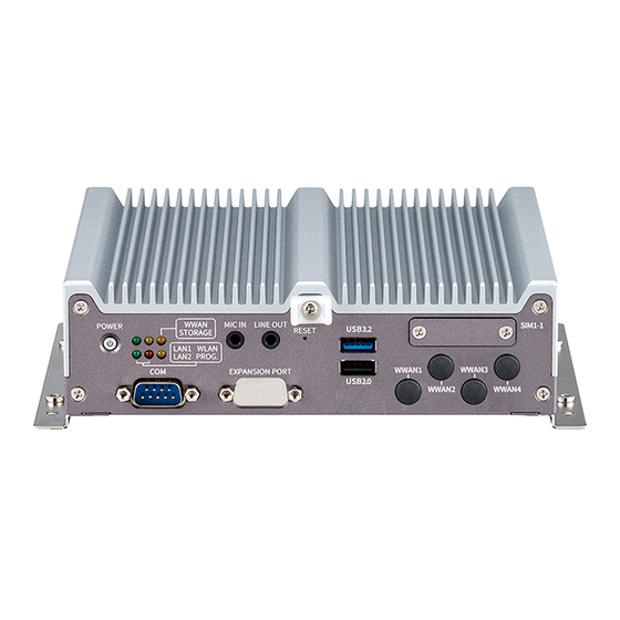
Page 36: Power Button
Red color (Blinking) when input power is 6~9VDC Program LED Stay On Programmable LED WWAN Yellow Stay On WWAN active Storage Yellow Blinking Storage access Copyright © 2023 NEXCOM International Co., Ltd. All Rights Reserved. VTC 1031 and nROK 1031 Series User Manual... -
Page 37: Mic-In Connector
Line-Out Connector Connector number: 3 Connector number: 4 Definition Definition Definition Definition MIC1-CR MIC1_JD FRONT_RI FRONT_JD MIC1-CL FRONT_LI AGND AGND AGND AGND Copyright © 2023 NEXCOM International Co., Ltd. All Rights Reserved. VTC 1031 and nROK 1031 Series User Manual... -
Page 38: Reset Switch
USB 3.2 Gen 2 Connector Number: 5/SW1 Connector number: 6 Definition Definition Open Normal (Default) Short Reset USB_0N USB_0P USB3_RX0N USB3_RX0P USB3_TX0N USB3_TX0P Copyright © 2023 NEXCOM International Co., Ltd. All Rights Reserved. VTC 1031 and nROK 1031 Series User Manual... -
Page 39: Usb 2.0
USB 2.0 SIM1 Micro-SIM Socket Connector number: 7 Connector number: 8 Definition Definition Definition UIM1_PWR_C UIM1_RST_C USB_1N UIM1_CLK_C USB_1P UIM1_DAT_C CD11 UIM1_CD_C Copyright © 2023 NEXCOM International Co., Ltd. All Rights Reserved. VTC 1031 and nROK 1031 Series User Manual... -
Page 40: Db9 (Com) For Full Rs232/Rs422/Rs485
Connector number: 10 This connector is an option and dedicated to the expansion. Definition Definition SP2_DCD#_TX- SP2_DSR# SP2_RX_TX+ SP2_RTS# SP2_TX_RX+ SP2_CTS# SP2_DTR#_RX- SP2_RI# COM2_GND Copyright © 2023 NEXCOM International Co., Ltd. All Rights Reserved. VTC 1031 and nROK 1031 Series User Manual... -
Page 41: Led For Poe1/Poe2
(VTC 1031-C2 and nROK 1031-C2 only) Connector number: 11 PoE1 PoE2 Color Description PoE1/PoE2 Green Lights up when the power is provided. Copyright © 2023 NEXCOM International Co., Ltd. All Rights Reserved. VTC 1031 and nROK 1031 Series User Manual... -
Page 42: Poe Lan1 Port
100Mbps network link Definition Definition Definition Definition LAN-1_MDI0P LAN-1_MDI2N LAN-2_MDI0P LAN-2_MDI2N LAN-1_MDI0N LAN-1_MDI1N LAN-2_MDI0N LAN-2_MDI1N LAN-1_MDI1P LAN-1_MDI3P LAN-2_MDI1P LAN-2_MDI3P LAN-1_MDI2P LAN-1_MDI3N LA-2N_MDI2P LAN-2_MDI3N Copyright © 2023 NEXCOM International Co., Ltd. All Rights Reserved. VTC 1031 and nROK 1031 Series User Manual... -
Page 43: Audio
LAN-1_MDI0P LAN-1_MDI3P AGND FRONT_JD LAN-1_MDI0N LAN-1_MDI3N MIC_L FRONT_L LAN-1_MDI1P LAN-1_MDI2N MIC_JD FRONT_R LAN-1_MDI1N LAN-1_MDI2P *Network speed is supported up to 2.5Gbps (10/100/1000/2500Mbps). Copyright © 2023 NEXCOM International Co., Ltd. All Rights Reserved. VTC 1031 and nROK 1031 Series User Manual... -
Page 44: Poe M12 X-Coded 8-Pin Lan2 Connector
Definition Definition Definition LAN-2_MDI0P LAN-2_MDI3P GND_IN LAN-2_MDI0N LAN-2_MDI3N V_IN LAN-2_MDI1P LAN-2_MDI2N IGNITION LAN-2_MDI1N LAN-2_MDI2P *Network speed is supported up to 2.5Gbps (10/100/1000/2500Mbps). Copyright © 2023 NEXCOM International Co., Ltd. All Rights Reserved. VTC 1031 and nROK 1031 Series User Manual... -
Page 45: Rj45 Lan1 Port
LAN-2_MDI1P LAN-2_MDI3P LAN-1_MDI2P LAN-1_MDI3N LA-2N_MDI2P LAN-2_MDI3N *Network speed is supported up to 2.5Gbps (10/100/1000/2500Mbps). *Network speed is supported up to 2.5Gbps (10/100/1000/2500Mbps). Copyright © 2023 NEXCOM International Co., Ltd. All Rights Reserved. VTC 1031 and nROK 1031 Series User Manual... -
Page 46: Screw Hole For Hdmi Wire Mount
2. Place the HDMI wire mount against the HDMI connector then secure it using a screw. 3. Hold the HDMI connector firmly against the wire mount and tighten with a tie wrap. Copyright © 2023 NEXCOM International Co., Ltd. All Rights Reserved. VTC 1031 and nROK 1031 Series User Manual... -
Page 47: Hdmi
HDMIDDCSDA RS485-2_- DB26G_GND HDMI_TX0P RS485-1_+ RS485-1_- HDMI_P5V G_O_1 G_O_2 HDMI_TX0N HDMIHPD G_O_3 G_O_4 HDMI_CLK_P DB26G_GND DB26G_GND RS232_RXD RS232_TXD ODOMETER DIRECTION DB26G_GND 12VO Copyright © 2023 NEXCOM International Co., Ltd. All Rights Reserved. VTC 1031 and nROK 1031 Series User Manual... -
Page 48: Vga
Chapter 2: External Connectors Pinout Description Connector number: 23 Definition Definition VGA_RED VGA_5V VGA_GREEN VGA_BLUE VGA_DAT VGA_HSYNC VGA_VSYNC VGA_CLK Copyright © 2023 NEXCOM International Co., Ltd. All Rights Reserved. VTC 1031 and nROK 1031 Series User Manual... -
Page 49: Dc Input (Nrok 1031 And Nrok 1031-C2 Only)
Connector location: 24 Definition Definition Definition Definition LAN-1_MDI0P LAN-1_MDI3P LAN-1_MDI0N LAN-1_MDI3N IGNITION LAN-1_MDI1P LAN-1_MDI2N LAN-1_MDI1N LAN-1_MDI2P *Network speed is supported up to 2.5Gbps (10/100/1000/2500Mbps). Copyright © 2023 NEXCOM International Co., Ltd. All Rights Reserved. VTC 1031 and nROK 1031 Series User Manual... -
Page 50: M12 X-Coded 8-Pin Lan2 Connector
USB1_N USB1_P LAN-2_MDI0N LAN-2_MDI3N USB1_VCC5 USB1_GND LAN-2_MDI1P LAN-2_MDI2N USB2_N USB2_P LAN-2_MDI1N LAN-2_MDI2P USB2_VCC5 USB2_GND *Network speed is supported up to 1Gbps (10/100/1000Mbps). Copyright © 2023 NEXCOM International Co., Ltd. All Rights Reserved. VTC 1031 and nROK 1031 Series User Manual... -
Page 51: Chapter 3: Jumpers And Connectors
Static electricity can damage many of the electronic ▪ Use correct screws and do not over tighten screws. components. Humid environments tend to have less static electricity than Copyright © 2023 NEXCOM International Co., Ltd. All Rights Reserved. VTC 1031 and nROK 1031 Series User Manual... -
Page 52: Jumper Settings
(on) and open (off). Two-Pin Jumpers: Open (Left) and Short (Right) Three-Pin Jumpers: Pins 1 and 2 are Short Copyright © 2023 NEXCOM International Co., Ltd. All Rights Reserved. VTC 1031 and nROK 1031 Series User Manual... -
Page 53: Locations Of The Internal Jumpers And Connectors
VTC 1031 and nROK 1031 series motherboards, as well as the storage expansion board. Top View CN10 CN13 J1 J3 CN15 CN14 ESPI_DB1 CN12 CN16 IDE2 CN11 IDE1 USB1 Copyright © 2023 NEXCOM International Co., Ltd. All Rights Reserved. VTC 1031 and nROK 1031 Series User Manual... -
Page 54: Bottom View
Chapter 3: Jumpers and Connectors Bottom View CN17 Copyright © 2023 NEXCOM International Co., Ltd. All Rights Reserved. VTC 1031 and nROK 1031 Series User Manual... -
Page 55: Storage Expansion Board
Chapter 3: Jumpers and Connectors Storage Expansion Board SATA1 Copyright © 2023 NEXCOM International Co., Ltd. All Rights Reserved. VTC 1031 and nROK 1031 Series User Manual... -
Page 56: Jumpers
2 ON RS485_2 Terminator Resistor (Default) RTC Clear CMOS 1 OFF 2 OFF RS485_1/2 None Terminator Resistor 1 ON 2ON ME Clear Copyright © 2023 NEXCOM International Co., Ltd. All Rights Reserved. VTC 1031 and nROK 1031 Series User Manual... -
Page 57: Pio Pull-High Selection Switch
GPO2 Internal Pull High (Default) External Pull High GPO3 Internal Pull High (Default) External Pull High GPO4 Internal Pull High (Default) External Pull High Copyright © 2023 NEXCOM International Co., Ltd. All Rights Reserved. VTC 1031 and nROK 1031 Series User Manual... -
Page 58: Can Terminator Resistor Selection Switch
Connector size: 2 x 2 = 4-pin switch Connector location: SW7 Definition 1 ON 2 ON CAN Terminator Resistor (Default) 1 OFF 2 OFF CAN None Terminator Resistor Copyright © 2023 NEXCOM International Co., Ltd. All Rights Reserved. VTC 1031 and nROK 1031 Series User Manual... -
Page 59: Connector Pin Definitions
12VSB USB_7N_T VCC3 12VSB USB_7P_T VCC3 12VSB LANRST# CLKREQ1#_R 12VSB PCIE_TXP4 PCIE_TXP1 PCIE_TXN4 PCIE_TXN1 PCIE_RP4 PCIE_RP1 PCIE_RN4 PCIE_RN1 PCIE_CLK_P4_R PCIE_CLK_P1_R PCIE_CLK_N4_R PCIE_CLK_N1_R Copyright © 2023 NEXCOM International Co., Ltd. All Rights Reserved. VTC 1031 and nROK 1031 Series User Manual... -
Page 60: 3042/3050/3052 Key B Socket
KEY(Notch location) KEY(Notch location) KEY(Notch location) PCM_CLK CONFIG_0 PCM_RX WAKE#_3G PCM_TX W_RESET# W_DISABLE2# CONFIG_1 V3.5G_P_A PCM_SYNC V3.5G_P_A USB3_RX1N UIM_RST_A V3.5G_P_A USB3_RX1P UIM_CLK_A CONFIG_2 Copyright © 2023 NEXCOM International Co., Ltd. All Rights Reserved. VTC 1031 and nROK 1031 Series User Manual... -
Page 61: Full Size Mini-Pcie Socket (Usb 2.0, Pcie 3.0)
PCIE_WAKE#2 +V3.3_MINI_2 +V1.5S_MINI_2 +V1.5S_MINI_2 PE_TX2N CLKREQ#1 PE_TX2P USB_1N PCIE_CLKN2 USB_1P PCIE_CLKP2 +V3.3_MINI_2 +V3.3_MINI_2 PCIE_WLAN_LED#B PCIE_DIS#2 PCIE_RST#2 +V1.5S_MINI_2 PE_RX2N +V3.3_MINI_2 PE_RX2P MBT_DIS#_R2 +V3.3_MINI_2 Copyright © 2023 NEXCOM International Co., Ltd. All Rights Reserved. VTC 1031 and nROK 1031 Series User Manual... -
Page 62: 3042 Key B Socket
KEY(Notch location) KEY(Notch location) KEY(Notch location) KEY(Notch location) KEY(Notch location) CONFIG_0_B W_RESET#_R_B W_DISABLE2#_B CONFIG_1_B V3.5G_P_B V3.5G_P_B USB3_RX2N UIM_RST_B V3.5G_P_B USB3_RX2P UIM_CLK_B CONFIG_2_B Copyright © 2023 NEXCOM International Co., Ltd. All Rights Reserved. VTC 1031 and nROK 1031 Series User Manual... -
Page 63: 2230 Key E Socket (Usb 2.0, Pcie 3.0X2)
SUSCLK RST0# CLKREQ0# BT_DIS# PEWAKE# WIFI_DIS# SM1_D WLAN2_LED# PCIE_TXP3 SM1_C PCIE_TXN3 I2C_ALERT# PCIE_RXP1 RST1# PCIE_RXN1 CLKREQ1# PCIE_TXP2 PCIE_CLKP1 VCC3 PCIE_TXN2 PCIE_CLKN1 VCC3 Copyright © 2023 NEXCOM International Co., Ltd. All Rights Reserved. VTC 1031 and nROK 1031 Series User Manual... -
Page 64: Audio Connector
SURR_OUT_L_CA SURR_JD UIM2_PWR_C UIM2_RST_C SURR_OUT_R_CA MIC1_OUT-R UIM2_CLK_C MIC_JD AGND UIM2_DAT_C CD11 UIM2_CD_C IDE2 Connector Pin Definition Definition Definition UIM2_DAT_A UIM2_CLK_A UIM2_RST_A UIM2_PWR_A Copyright © 2023 NEXCOM International Co., Ltd. All Rights Reserved. VTC 1031 and nROK 1031 Series User Manual... -
Page 65: Sata Board To Board Connector
Definition Definition Definition SATA_TXP0 VCC5 M.2_SSD_LED# SATA_TXN0 VCC5 SATA_RXN0 VCC5 VCC3 SATA_RXP0 VCC5 VCC3 VCC3 SATA_TXP1 VCC3 SATA_TXN1 SATA_RXN1 SATA_RXP1 USB2_P8 USB2_N8 Copyright © 2023 NEXCOM International Co., Ltd. All Rights Reserved. VTC 1031 and nROK 1031 Series User Manual... -
Page 66: Espi Debug Port Connector
Definition PLTRST# USB2_POWER USB2_N6 ESPI_CLK_HDR ESPI_CS0_HDR# USB2_P6 ESPI_IO3_HDR ESPI_IO2_HDR ESPI_IO1_HDR ESPI_IO0_HDR ESPI_RST_HDR# 3VSB J3 Connector Pin Definition Definition Definition USB2_POWER USB2_N5 USB2_P5 Copyright © 2023 NEXCOM International Co., Ltd. All Rights Reserved. VTC 1031 and nROK 1031 Series User Manual... -
Page 67: Rtc Battery Connector
Connector size: 1 x 4 = 4-pin header (1.00mm) Connector location: J2 Connector location: J5 J5 Connector Pin Definition Definition Definition Definition USB_9P VBAT USB_9N USB_POWER Copyright © 2023 NEXCOM International Co., Ltd. All Rights Reserved. VTC 1031 and nROK 1031 Series User Manual... -
Page 68: Com Connector (Rs232/422/485)
Connector location: J8 J7 Connector Pin Definition Definition Definition Definition Definition COM1_GND COM1_GND SP1_CTS# SP1_DSR# ODOMETER DIRECTION SP1_DTR#_RX- SP1_RX_TX+ SP1_RI# SP1_RTS# SP1_TX_RX+ SP1_DCD#_TX- Copyright © 2023 NEXCOM International Co., Ltd. All Rights Reserved. VTC 1031 and nROK 1031 Series User Manual... -
Page 69: Gnss Connector
Connector size: 1 x 3 = 3-pin header (1.0mm) Connector location: J9 Connector location: J11 Definition Definition Definition GPS_BAT MCU_TX6 GPS_TXD GPS_RXD MCU_RX6 GPS_3V3 Copyright © 2023 NEXCOM International Co., Ltd. All Rights Reserved. VTC 1031 and nROK 1031 Series User Manual... -
Page 70: Mcu Download Pin Header
MCU Download Pin Header Connector size: 2 x 4 = 8-pin header (1.27mm) Connector location: JP2 Definition Definition +V3.3ALW MCU_RST MCU_TRST MCU_TDI MCU_TCK MCU_TMS MCU_TDO Copyright © 2023 NEXCOM International Co., Ltd. All Rights Reserved. VTC 1031 and nROK 1031 Series User Manual... -
Page 71: Storage Board Connector
KEY(Notch location) KEY(Notch location) KEY(Notch location) CONFIG_0_B W_DISABLE2#_B USB3_RX2N UIM_RST_B W_RESET#_R_B USB3_RX2P UIM_CLK_B CONFIG_1_B V3.5G_P_B UIM_DAT_B V3.5G_P_B USB3_TX2N UIM_PWR_B V3.5G_P_B USB3_TX2P CONFIG_2_B Copyright © 2023 NEXCOM International Co., Ltd. All Rights Reserved. VTC 1031 and nROK 1031 Series User Manual... -
Page 72: Sata Connector
Chapter 3: Jumpers and Connectors SATA Connector Connector location: SATA1 Definition Definition SATA_PWR0 SATA_PWR0 SATA_PWR0 SATA_PCIE_DETP0 SATA_TXP0 SATA_TXN0 SATA_RXN0 SATA_RXP0 Copyright © 2023 NEXCOM International Co., Ltd. All Rights Reserved. VTC 1031 and nROK 1031 Series User Manual... -
Page 73: Chapter 4: System Setup
1. Remove the screws on the front panel. 2. Remove the screw on the rear panel. Copyright © 2023 NEXCOM International Co., Ltd. All Rights Reserved. VTC 1031 and nROK 1031 Series User Manual... - Page 74 5. After removing the screws described in the previous steps, open the bottom cover. 4. Remove the screws on the both sides. Copyright © 2023 NEXCOM International Co., Ltd. All Rights Reserved. VTC 1031 and nROK 1031 Series User Manual...
-
Page 75: Installing A Sata Hard Drive
1. Align the hard drive’s mounting holes with the mounting holes on the tor. hard drive bracket, and use the provided screws to secure the both sides of hard drive in place. Copyright © 2023 NEXCOM International Co., Ltd. All Rights Reserved. VTC 1031 and nROK 1031 Series User Manual... -
Page 76: Installing An M.2 Storage Device
Then fasten a screw into the mounting hole to secure the storage device. Copyright © 2023 NEXCOM International Co., Ltd. All Rights Reserved. VTC 1031 and nROK 1031 Series User Manual... -
Page 77: Removing The Poe Board
Removing the PoE Board for WWAN/WLAN/mSATA Module, Internal SIM Card, and Memory Installation on VTC 1031-C2 and nROK1031-C2 1. Remove the screws on the PoE board. For nROK1031-C2 For nROK1031-C2 PoE Board Copyright © 2023 NEXCOM International Co., Ltd. All Rights Reserved. VTC 1031 and nROK 1031 Series User Manual... - Page 78 Chapter 4: System Setup 2. Remove the PoE board. Copyright © 2023 NEXCOM International Co., Ltd. All Rights Reserved. VTC 1031 and nROK 1031 Series User Manual...
-
Page 79: Installing An Internal Sim Card
2. Place the sim card with the direction as shown in the following picture, then close the cover. Copyright © 2023 NEXCOM International Co., Ltd. All Rights Reserved. VTC 1031 and nROK 1031 Series User Manual... -
Page 80: Installing A Wwan Module (M.2)
45 degrees angle until the gold-plated connector on the edge of the mod- ule completely disappears inside the slot. Then fasten a screw in package into the mounting hole to secure the module. Copyright © 2023 NEXCOM International Co., Ltd. All Rights Reserved. VTC 1031 and nROK 1031 Series User Manual... - Page 81 Then fasten a screw into the mounting hole to secure the 3042 location using the appropriate tool. the module. 2. With the copper standoff removed, tighten it to the 3052 location. Copyright © 2023 NEXCOM International Co., Ltd. All Rights Reserved. VTC 1031 and nROK 1031 Series User Manual...
-
Page 82: Removing The Storage Board
Removing the Storage Board for WLAN/mSATA Module and Memory Installation Note: The PoE board should be removed before removing storage board on VTC 1031-C2 and nROK1031-C2 Storage Board Copyright © 2023 NEXCOM International Co., Ltd. All Rights Reserved. VTC 1031 and nROK 1031 Series User Manual... - Page 83 Chapter 4: System Setup 1. Remove the screws on the storage board. 2. Remove the storage board. Copyright © 2023 NEXCOM International Co., Ltd. All Rights Reserved. VTC 1031 and nROK 1031 Series User Manual...
-
Page 84: Installing A So-Dimm Memory Module
Note: The memory module has a foolproof design, be aware of the orientation when installing. Copyright © 2023 NEXCOM International Co., Ltd. All Rights Reserved. VTC 1031 and nROK 1031 Series User Manual... -
Page 85: Installing A Wlan Module
Then fasten screws into the mounting holes to secure the module. Copyright © 2023 NEXCOM International Co., Ltd. All Rights Reserved. VTC 1031 and nROK 1031 Series User Manual... - Page 86 45 degrees angle until the gold-plated connector on the edge of the module completely disappears inside the slot. Then fasten screws into the mounting holes to secure the module. Copyright © 2023 NEXCOM International Co., Ltd. All Rights Reserved. VTC 1031 and nROK 1031 Series User Manual...
-
Page 87: Installing A Msata Module
PCI Express slot at a 45 degrees angle until the gold-plated connector on the edge of the module completely disappears inside the slot. Then fasten screws into the mounting holes to secure the module. Copyright © 2023 NEXCOM International Co., Ltd. All Rights Reserved. VTC 1031 and nROK 1031 Series User Manual... -
Page 88: Installing A Sim Card
Remove the SIM card cover on the front panel and insert the SIM cards. Please take note of the SIM card installation direction as shown in the following pictures. Copyright © 2023 NEXCOM International Co., Ltd. All Rights Reserved. VTC 1031 and nROK 1031 Series User Manual... -
Page 89: Appendix A: Software Demo Utility For I/O Ports Of Function Control
NEXCOM developed a software demo utility to let users test and control different I/O port functions on VTC 1031/VTC 1031-C2/nROK 1031/nROK 1031-C2. This document shows how to use the utility. There are also the source code files of utility in official website. Users can refer to the source codes to develop their applications. - Page 90 - If the setting is 12V: 12V is shown. - If the setting is 24V: 24V is shown. - If the setting is 9V~36V: 9V~36V is shown. Copyright © 2023 NEXCOM International Co., Ltd. All Rights Reserved. VTC 1031 and nROK 1031 Series User Manual...
-
Page 91: System 2
Set WDT button. 2.1 Power ON/OFF Delay Timer Enables or disables the delay time function. There are several options of delay time for configuration. Copyright © 2023 NEXCOM International Co., Ltd. All Rights Reserved. VTC 1031 and nROK 1031 Series User Manual... -
Page 92: I/O
3. I/O 3.1 GPO Defines the GPO port as high or low. 3.2 GPI Get the GPI port as high or low. Copyright © 2023 NEXCOM International Co., Ltd. All Rights Reserved. VTC 1031 and nROK 1031 Series User Manual... - Page 93 Enables or disables the Wake On LAN function. Defines the Program LED as on or off. 3.4 External 12V Enables or disables the external power output. Copyright © 2023 NEXCOM International Co., Ltd. All Rights Reserved. VTC 1031 and nROK 1031 Series User Manual...
-
Page 94: Module
4.2 SIM Card Selects your SIM card setting on WWAN is from SIM Card1 or SIM Card2 (BOM optional for WWAN 2). Copyright © 2023 NEXCOM International Co., Ltd. All Rights Reserved. VTC 1031 and nROK 1031 Series User Manual... - Page 95 Shows “PCIE (CN15)” for Mini-PCIe socket or “USB (CN14)” for BOM optional M.2 socket. Enables or disables the Bluetooth function on CN16 or CN15. Copyright © 2023 NEXCOM International Co., Ltd. All Rights Reserved. VTC 1031 and nROK 1031 Series User Manual...
-
Page 96: Event
Shows the event of VTC 1031 / VTC 1031–C2 / nROK 1031 / nROK 1031-C2. (Information) Date: YYMMDD Time: HHMMSS GPS Status: 0: Searching 1: Fixed Copyright © 2023 NEXCOM International Co., Ltd. All Rights Reserved. VTC 1031 and nROK 1031 Series User Manual... -
Page 97: G-Sensor
Set Output data rate and Full-scale for accelerometer. Read the data from accelerometer. 6.2 Gyroscope Set Output data rate and Full-scale for gyroscope. Read the data from gyroscope. Copyright © 2023 NEXCOM International Co., Ltd. All Rights Reserved. VTC 1031 and nROK 1031 Series User Manual... - Page 98 Appendix A: Software Demo Utility for I/O Ports of Function Control 6.3 Register Table Shows the value of all registers in accelerometer and gyroscope, once the Refresh button is pressed. Copyright © 2023 NEXCOM International Co., Ltd. All Rights Reserved. VTC 1031 and nROK 1031 Series User Manual...
-
Page 99: Can Bus
Listen-Only: Only receive data, including receiving wrong data Defines Rollover as the following options: • Enable: Receive buffer 1 and buffer 2 data • Disable: Only receive buffer data Copyright © 2023 NEXCOM International Co., Ltd. All Rights Reserved. VTC 1031 and nROK 1031 Series User Manual... - Page 100 (Transmit message 3 data). Check Show Message to display the sent information. If not check, it will not display. Copyright © 2023 NEXCOM International Co., Ltd. All Rights Reserved. VTC 1031 and nROK 1031 Series User Manual...
-
Page 101: Appendix B: Gnss Feature
Software migration requires little effort thanks to the continuous support of UBX messages across product generations. Copyright © 2023 NEXCOM International Co., Ltd. All Rights Reserved. VTC 1031 and nROK 1031 Series User Manual... - Page 102 32 mA at 3.0 V (2 GNSS continous) 28 mA at 3.0 V (1 GNSS continous) Backup Supply 1.65 V to 3.6 V Copyright © 2023 NEXCOM International Co., Ltd. All Rights Reserved. VTC 1031 and nROK 1031 Series User Manual...
- Page 103 J2 (GNSS Side) J9 (GNSS Side) J2 Pin Definition Definition Definition GPS_3V3 GPS_TXD_M GPS_RXD_M +V3.3ALW J9 Pin Definition Definition Definition 3.3V_BAT 3.3V Copyright © 2023 NEXCOM International Co., Ltd. All Rights Reserved. VTC 1031 and nROK 1031 Series User Manual...
-
Page 104: U-Blox Neo-M9L Overview
3D sensing also enables flexibility in orientation of the receiver with respect to the vehicle frame. With future flash firmware update. Copyright © 2023 NEXCOM International Co., Ltd. All Rights Reserved. VTC 1031 and nROK 1031 Series User Manual... -
Page 105: Technical Specifications
Higher bandwidths are used for navigation Maximum navigation Assuming Airborne < 4 g platform rate 20 Hz (High Rate output) Copyright © 2023 NEXCOM International Co., Ltd. All Rights Reserved. VTC 1031 and nROK 1031 Series User Manual... - Page 106 J9 Pin Definition Definition Definition Definition Definition GPS_BAT ODOMETER DIRECTION GPS_TXD GPS_RXD VCC3_GPS COM Port for GPS: COM 4 Baud Rate: 9600 Copyright © 2023 NEXCOM International Co., Ltd. All Rights Reserved. VTC 1031 and nROK 1031 Series User Manual...
-
Page 107: Appendix D: Signal Connection Of Di/Do
PPendIx IGnal onneCtIon of Multi Port Pinout Description Definition Definition G_I_5 G_I_4 G_I_3 G_I_2 G_I_1 G_O_1 G_O_2 G_O_3 G_O_4 DB26G_GND Copyright © 2023 NEXCOM International Co., Ltd. All Rights Reserved. VTC 1031 and nROK 1031 Series User Manual... -
Page 108: Digital Input
The figure below shows how to connect an external source to one of the The figure below shows how to connect an external source to one of the input channels. input channels. Copyright © 2023 NEXCOM International Co., Ltd. All Rights Reserved. VTC 1031 and nROK 1031 Series User Manual... -
Page 109: Digital Output
The figure below shows how to connect an external source to one of the output The figure below shows how to connect an external source to one of the channels. output channels. Copyright © 2023 NEXCOM International Co., Ltd. All Rights Reserved. VTC 1031 and nROK 1031 Series User Manual... -
Page 110: Appendix E: Pin Definition For The Multiport Cable
A connector and its corresponding pin signals to the output connector. VTC 1031 / VTC 1031-C2 nROK 1031 / nROK 1031-C2 Copyright © 2023 NEXCOM International Co., Ltd. All Rights Reserved. VTC 1031 and nROK 1031 Series User Manual... -
Page 111: P1 Connector Pinout
G_I_3 G_I_2 ODOMETER G_I_1 RS485-2_+ DIRECTION RS485-2_- DB26G_GND RS485-1_+ RS485-1_- G_O_1 G_O_2 G_O_3 G_O_4 DB26G_GND DB26G_GND RS232_RXD RS232_TXD ODOMETER DIRECTION DB26G_GND 12VO Copyright © 2023 NEXCOM International Co., Ltd. All Rights Reserved. VTC 1031 and nROK 1031 Series User Manual... -
Page 112: P3 Connector Pinouts
P3 Connector Pinouts P4 Connector Pinouts COM connector: P3 RS485-2 connector: P4 P1 Pin P3 Pin Definition P1 Pin P4 Pin Definition RS485-2+ RS485-2- Copyright © 2023 NEXCOM International Co., Ltd. All Rights Reserved. VTC 1031 and nROK 1031 Series User Manual... -
Page 113: P5 Connector Pinouts
GPIO connector: P6 P1 Pin P5 Pin Definition P1 Pin P6 Pin Definition GPI-5 RS485-1+ GPI-4 RS485-1- GPI-3 GPI-2 GPI-1 GPO-1 GPO-2 GPO-3 GPO-4 Copyright © 2023 NEXCOM International Co., Ltd. All Rights Reserved. VTC 1031 and nROK 1031 Series User Manual... -
Page 114: P7 Connector Pinouts
Appendix E: Pin Definition for the Multiport Cable P7 Connector Pinouts Power Output connector: P7 P1 Pin P7 Pin Definition VCC 12V- VCC 12V+ Copyright © 2023 NEXCOM International Co., Ltd. All Rights Reserved. VTC 1031 and nROK 1031 Series User Manual... - Page 115 The tables in this appendix list the pin signals of the P1 connector and its corresponding pin signals to the output connectors. nROK 1031 nROK 1031-C2 Copyright © 2023 NEXCOM International Co., Ltd. All Rights Reserved. VTC 1031 and nROK 1031 Series User Manual...
-
Page 116: P1 Connector Pinout
P1 Pin P2 Pin Definition P1 Pin P3 Pin Definition AGND FRONT_JD AGND FRONT_JD MIC_L FRONT_L MIC_L FRONT_L MIC_JD FRONT_R MIC_JD FRONT_R Copyright © 2023 NEXCOM International Co., Ltd. All Rights Reserved. VTC 1031 and nROK 1031 Series User Manual... - Page 117 The tables in this appendix list the pin signals of the CN1 connector and its corresponding pin signals to the output connectors nROK 1031 / nROK 1031-C2 Copyright © 2023 NEXCOM International Co., Ltd. All Rights Reserved. VTC 1031 and nROK 1031 Series User Manual...
-
Page 118: Cn1 Connector Pinout
CN1 Connector Pinout CN2 and CN3 Connector Pinouts USB connector: CN2, CN3 Definition Definition CN1 Pin CN2 Pin Definition CN1 Pin CN3 Pin Definition Copyright © 2023 NEXCOM International Co., Ltd. All Rights Reserved. VTC 1031 and nROK 1031 Series User Manual... -
Page 119: Appendix F: Vehicle Power Management Setup
F4: Save & Exit F4: Save & Exit ESC: Exit ESC: Exit Version 2.22.1282 Copyright (C) 2022 AMI Version 2.22.1282 Copyright (C) 2022 AMI Copyright © 2023 NEXCOM International Co., Ltd. All Rights Reserved. VTC 1031 and nROK 1031 Series User Manual... -
Page 120: Power-Off Delay Setting
F4: Save & Exit F4: Save & Exit ESC: Exit ESC: Exit Version 2.22.1282 Copyright (C) 2022 AMI Version 2.22.1282 Copyright (C) 2022 AMI Copyright © 2023 NEXCOM International Co., Ltd. All Rights Reserved. VTC 1031 and nROK 1031 Series User Manual... - Page 121 F4: Save & Exit F4: Save & Exit ESC: Exit ESC: Exit Version 2.22.1282 Copyright (C) 2022 AMI Version 2.22.1282 Copyright (C) 2022 AMI Copyright © 2023 NEXCOM International Co., Ltd. All Rights Reserved. VTC 1031 and nROK 1031 Series User Manual...
-
Page 122: Appendix G: Power Consumption
PoE board (30W + 30W) All Storage (M.2 SATA SSD + 2.5” SATA SSD) M.2 Hailo Module (Mini PCIE WLAN + M.2 WWAN + M.2 Hailo) Copyright © 2023 NEXCOM International Co., Ltd. All Rights Reserved. VTC 1031 and nROK 1031 Series User Manual... - Page 123 Full state IGNITION OFF 24V wake up WWAN 0.04 0.96 0.01 0.36 36V wake up WWAN 0.03 1.08 *WWAN: Enable wakeup function of WWAN module Copyright © 2023 NEXCOM International Co., Ltd. All Rights Reserved. VTC 1031 and nROK 1031 Series User Manual...
Need help?
Do you have a question about the VTC 1031 Series and is the answer not in the manual?
Questions and answers