
Related Manuals for Nexcom VTC 1911


Summary of Contents for Nexcom VTC 1911
- Page 1 NEXCOM International Co., Ltd. Mobile Computing Solutions Vehicle Telematics Computer VTC 1911 User Manual NEXCOM International Co., Ltd. www.nexcom.com Published October 2018...
-
Page 2: Table Of Contents
SATA Power Connector ..............18 Chapter 2: External Connectors Pinout Description VGA ....................18 Add-on Card Cable ................19 SIM1 and SIM2 Slots ................6 Internal USB Connector for WLAN/CAN05/06 Capture Module ..19 Copyright © 2018 NEXCOM International Co., Ltd. All Rights Reserved. VTC 1911 User Manual... - Page 3 Appendix C: Signal Connection of MCU DI/DO 1.2 Boot Mode .................33 MCU DIO Pinout Description ..............41 1.3 OS Control .................33 Digital Input ..................41 1.4 WWAN ..................33 Digital Output ..................42 1.5 MDO ..................33 Copyright © 2018 NEXCOM International Co., Ltd. All Rights Reserved. VTC 1911 User Manual...
- Page 4 P5 Connector Pinout ................55 P1 to P4 Connector Pinouts ..............55 COM1 (RS232 Tx/Rx) Connector ............55 COM2 (RS232 Tx/Rx) Connector ............56 GPIO Connector ................56 CAN1 Connector ................57 Copyright © 2018 NEXCOM International Co., Ltd. All Rights Reserved. VTC 1911 User Manual...
-
Page 5: Preface
Acknowledgements The product(s) described in this manual complies with all applicable VTC 1911 is a trademark of NEXCOM International Co., Ltd. All other European Union (CE) directives if it has a CE marking. For computer systems product names mentioned herein are registered trademarks of their to remain CE compliant, only CE-compliant parts may be used. -
Page 6: Rohs Compliance
0.1% or 1,000ppm, and Polybrominated diphenyl Ethers (PBDE) < 0.1% or 1,000ppm. In order to meet the RoHS compliant directives, NEXCOM has established an engineering and manufacturing task force in to implement the introduction of green products. The task force will ensure that we follow the standard... -
Page 7: Warranty And Rma
▪ Replace with 3rd party products if needed. ▪ Customers must collect all the information about the problems ▪ If RMA goods can not be repaired, NEXCOM will return it to the customer encountered and note anything abnormal or, print out any on-screen without any charge. - Page 8 Always power off the system before inserting or removing the SIM only with the same or equivalent type recommended by the manufacturer. card. Discard used batteries according to the manufacturer’s instructions. viii Copyright © 2018 NEXCOM International Co., Ltd. All Rights Reserved. VTC 1911 User Manual...
- Page 9 ▪ The computer is provided with CD drives that comply with the appropriate ▪ All cautions and warnings on the equipment should be noted. safety standards including IEC 60825. Copyright © 2018 NEXCOM International Co., Ltd. All Rights Reserved. VTC 1911 User Manual...
-
Page 10: Technical Support And Assistance
Preface Technical Support and Assistance Conventions Used in this Manual 1. For the most updated information of NEXCOM products, visit NEXCOM’s Warning: website at www.nexcom.com. Information about certain situations, which if not observed, can cause personal injury. This will prevent injury to yourself 2. -
Page 11: Global Service Contact Information
13F, No.920, Chung-Cheng Rd., ZhongHe District, Beijing, 100094, China New Taipei City, 23586, Taiwan, R.O.C. Tel: +86-10-5704-2680 Tel: +886-2-8226-7796 Fax: +86-10-5704-2681 Fax: +886-2-8226-7792 Email: sales@nexcom.cn Email: sales@nexcom.com.tw www.nexcom.cn www.nexcom.com.tw Copyright © 2018 NEXCOM International Co., Ltd. All Rights Reserved. VTC 1911 User Manual... - Page 12 Hui Yin Ming Zun Building Room 1108, Building No. 11, 599 Yunling Road, Putuo District, Shanghai, 200062, China Tel: +86-21-6125-8282 Fax: +86-21-6125-8281 Email: frankyang@nexcom.cn www.nexcom.cn Copyright © 2018 NEXCOM International Co., Ltd. All Rights Reserved. VTC 1911 User Manual...
-
Page 13: Package Contents
Preface Package Contents Before continuing, verify that the VTC 1911 package that you received is complete. Your VTC 1911 package should have all the items listed in the following table. Item Name Specification 602DCD1544X00 VTC1911-IPK Series DVD Driver VER:1.0 603POW0242X00... -
Page 14: Ordering Information
DIMM, U-blox M8N GPS on board, VGA output, 2 x LAN, 2 x RS-232 (Tx/Rx), 1 x RS-485 (Tx/Rx), 1 x CAN 2.0B, 3 x DI, 3 x DO, 1 x USB 2.0, 1 x Line-out/Mic-in Copyright © 2018 NEXCOM International Co., Ltd. All Rights Reserved. VTC 1911 User Manual... -
Page 15: Chapter 1: Product Introduction
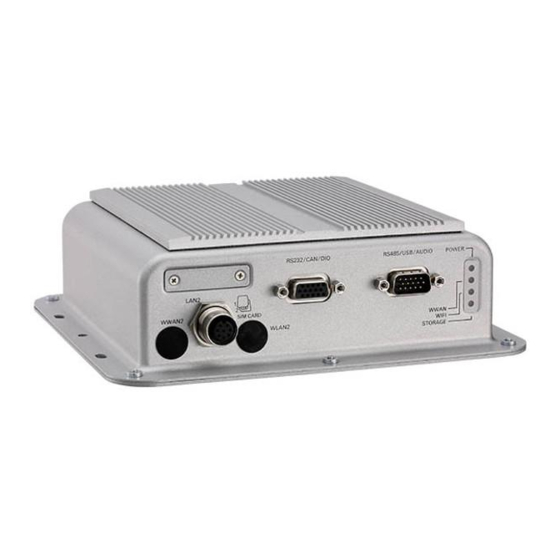
Physical Features Front View Rear View SIM1 / SIM2 slot cover RS232/CAN/DIO RS485/USB/AUDIO indicators Antenna holes Antenna holes DC IN LAN1 9V-36V LAN2 GPS antenna connector Copyright © 2018 NEXCOM International Co., Ltd. All Rights Reserved. VTC 1911 User Manual... -
Page 16: Overview
• Additional waterproof HDMI connector (by request) VTC 1911-IPK has onboard CAN 2.0B and optional OBD interface (SAE • Smart power management with ignition on/off delay via software J1939/J1708) for vehicle diagnostics and driver behavior management. An control and low voltage protection advanced GPS receiver supports GPS/Glonass/QZSS/Galileo/Beidou. -
Page 17: Hardware Specifications
– Damp heat test per EN60068-2-30 ▪ Humidity – 1 x Optional VIOB-CAN-05/06 or 2 x video input – IEC60068-2-3, damp heat steady state test, 40°C, 95%, 48Hrs Copyright © 2018 NEXCOM International Co., Ltd. All Rights Reserved. VTC 1911 User Manual... - Page 18 ▪ Shock – MIL-STD-810G, 516.6 Procedure I, trucks and semi-trailers=40g – Crash hazard: Procedure V, ground equipment=75g Certifications ▪ CE ▪ FCC Class A ▪ E13 Copyright © 2018 NEXCOM International Co., Ltd. All Rights Reserved. VTC 1911 User Manual...
-
Page 19: Connector Numbering
The following diagrams indicate the numbers of the connectors. Use these numbers to locate the connectors’ respective pinout assignments on chapter 2 of the manual. Copyright © 2018 NEXCOM International Co., Ltd. All Rights Reserved. VTC 1911 User Manual... -
Page 20: Chapter 2: External Connectors Pinout Description
G_OUT_1 UIM1 CLK UIM1 DATA ISO_CAN1_L RS232_TXD1 RS232_RXD2 G_IN3 SIM2 G_OUT3 ISO_CAN1_H RS232_TXD2 G_IN2 Definition Definition G_OUT2 UIM2 POWER ISO_GND UIM2 RST UIM2 CLK UIM2 DATA Copyright © 2018 NEXCOM International Co., Ltd. All Rights Reserved. VTC 1911 User Manual... -
Page 21: Rs485/Usb/Audio Connector
POWER Power On: Green MCU_485_TX- SPK_OUT_R WWAN Blinking: Active MIC_R_IN USB+ WIFI Blinking: Active MCU_485_TX+ STORAGE Light On: Storage Active SPK_OUT_L MIC_L_IN DATA_L DATA_H DATA_GND Audio_GND Copyright © 2018 NEXCOM International Co., Ltd. All Rights Reserved. VTC 1911 User Manual... -
Page 22: M12 Lan Ports: Lan1/Lan2
Chapter 2: External Connectors Pinout Description M12 LAN Ports: LAN1/LAN2 Power Connector Connector number: 5 Connector number: 6 Definition Definition Definition Definition LAN_MDI_0P_R LAN_MDI_0N_R LAN_MDI_1P_R LAN_MDI_1N_R LAN_MDI_2P_R LAN_MDI_2N_R IGNITION LAN_MDI_3P_R LAN_MDI_3N_R Copyright © 2018 NEXCOM International Co., Ltd. All Rights Reserved. VTC 1911 User Manual... -
Page 23: Vga Port
VGA_GREEN VGA_BLUE VGA_GND HDMI_TX2N_L HDMI_TX1P_L HDMI_TX1N_L VGA_GND VGA_GND VGA_GND VGA_GND HDMI_TX0P_L HDMI_TX0N_L HDMI_CLK_P_L VGA +5V VGA_GND VGA_GND VGA_DATA HDMI_CLK_N_L VGA_HS VGA_VS VGA_CLK HDMI_SCL HDMI_SDA HDMI_P5V HDMI_HPD Copyright © 2018 NEXCOM International Co., Ltd. All Rights Reserved. VTC 1911 User Manual... -
Page 24: Chapter 3: Jumpers And Switches
3: J haPter umPers and wItChes This chapter describes how to set the jumpers on the VTC 1911 motherboard. Precautions Before You Begin ▪ Ensure you have a stable, clean working environment. Dust and dirt can Computer components and electronic circuit boards can be damaged by discharges of static electricity. -
Page 25: Jumper Settings
(on) and open (off). Two-Pin Jumpers: Open (Left) and Short (Right) Three-Pin Jumpers: Pins 1 and 2 are Short Copyright © 2018 NEXCOM International Co., Ltd. All Rights Reserved. VTC 1911 User Manual... - Page 26 Chapter 3: Jumpers and Switches VTC 1911 Connector Specification & Jumper Setting VTC 1911 carrier board placement The figure below is the carrier board used in the VTC 1911 system. It shows the locations of the jumpers and connectors. LED4 CN11 CN6 J5 Copyright ©...
-
Page 27: Dip Switch Settings
1 OFF, 2 OFF ME Normal (Default) 1 OFF, 2 ON RTC Clear CMOS 1 ON, 2 ON 9-36V (Default) 1 ON, 2 ON ME Clear Copyright © 2018 NEXCOM International Co., Ltd. All Rights Reserved. VTC 1911 User Manual... -
Page 28: Gpio Pull High Enable
CAN2 None Terminator Resistor GPO2 On: enable pull high Off: dis pull high GPO3 On: enable pull high Off: dis pull high (Default enable pull high) Copyright © 2018 NEXCOM International Co., Ltd. All Rights Reserved. VTC 1911 User Manual... -
Page 29: Wwan I2S Tx/Rx Mapping Selection Switch
WWAN I2S TX/RX Mapping Selection Switch Connector location: SW1 1 2 3 4 Definition Definition PCM_TX PCM_RX PCM_TX PCM_RX PCM_RX_SW PCM_RX_SW PCM_TX_SW PCM_TX_SW (Default 1/4: on, 2/3: off) Copyright © 2018 NEXCOM International Co., Ltd. All Rights Reserved. VTC 1911 User Manual... -
Page 30: Lan1
Connector location: J1 and J2 Definition Definition Definition Definition LAN1_MDI_0P_R LAN1_MDI_0N_R LAN2_MDI_0P_R LAN2_MDI_0N_R LAN1_MDI_1P_R LAN1_MDI_1N_R LAN2_MDI_1P_R LAN2_MDI_1N_R Definition Definition Definition Definition LAN1_MDI_2P_R LAN1_MDI_2N_R LAN2_MDI_2P_R LAN2_MDI_2N_R LAN1_MDI_3P_R LAN1_MDI_3N_R LAN2_MDI_3P_R LAN2_MDI_3N_R Copyright © 2018 NEXCOM International Co., Ltd. All Rights Reserved. VTC 1911 User Manual... -
Page 31: Battery Connector
Connector size: 1 x 2 = 2-pin header (1.25mm) Connector size: 1 x 2 = 2-pin header Connector location: J4 Connector location: J5 Definition Definition RTC_BAT RESET Copyright © 2018 NEXCOM International Co., Ltd. All Rights Reserved. VTC 1911 User Manual... -
Page 32: Sata Power Connector
Connector location: J6 and J8 Connector location: J11 Definition Definition Definition VGA_+5V VCC5 VGA_CLK VGA_DATA VGA_VS VGA_HS VGA_GND Definition VGA_BLUE VGA_GND VCC5 VGA_GREEN VGA_GND VGA_RED VGA_GND Copyright © 2018 NEXCOM International Co., Ltd. All Rights Reserved. VTC 1911 User Manual... -
Page 33: Add-On Card Cable
Connector size: 1 x 3 = 3-pin header (1.0mm) Connector location: J12 Connector size: 1 x 16 = 16-pin header (1.0mm) Connector location: J13 Definition Definition Definition USB_5V USB_3N DATA_H1 USB_3P DATA_L2 WLAN_LED# WLAN_DIS# Copyright © 2018 NEXCOM International Co., Ltd. All Rights Reserved. VTC 1911 User Manual... -
Page 34: Gps Antenna Connector
GPS Antenna Connector GPS Battery Connector Connector location: CN1 Connector size: 1 x 2 = 2-pin header (1.25mm) Connector location: CN5 Definition Definition RF_IN BACKUP_VOT (3.3V) Copyright © 2018 NEXCOM International Co., Ltd. All Rights Reserved. VTC 1911 User Manual... -
Page 35: Power On/Off Button
Connector size: 1 x 2 = 2-pin header (1.0mm) Connector size: 1 x 7 = 7-pin header (1.27mm) Connector location: CN6 Connector location: CN7 Definition Definition Definition PWRBT_IN# SATA_TXP0 SATA_TXN0 SATA_RXN0 SATA_RXP0 Copyright © 2018 NEXCOM International Co., Ltd. All Rights Reserved. VTC 1911 User Manual... -
Page 36: Led
Definition Definition Function Definition LED_A1 LED_C1 Power LED (BLUE) (RED) WWAN_LED IGNITION WWAN_LED_C WWAN LED (GREEN) WLED_LED W_LED_C WLAN LED (GREEN) SATA_LED SATA_LED_C SATA LED (YELLOW) Copyright © 2018 NEXCOM International Co., Ltd. All Rights Reserved. VTC 1911 User Manual... -
Page 37: Hdmi Bd To Bd
Connector size: 2 x 15 = 30-pin header Connector location: JP5 Definition Definition HDMI_HPD DPC0_LANE0_P_C DPC0_LANE0_N_C DPC0_LANE1_P_C DPC0_LANE1_N_C DPC0_LANE2_P_C DPC0_LANE2_N_C DPC0_LANE3_P_C DPC0_LANE3_N_C VCC3 VCC3 HDMI_DATA VCC5 HDMI_CLK VCC5 Copyright © 2018 NEXCOM International Co., Ltd. All Rights Reserved. VTC 1911 User Manual... -
Page 38: Mini-Pcie Slot (Wwan Connector)
* When it is supporting VIOB-DA-01, Pin1 => MIC_P; Pin3, 7 => GND; Pin5 => SPK_P; Pin17 => PCM_DATA; Pin 19 => PCM_CLK. * When it is not supporting VIOB-DA-01, Pin1 => Wake#; Pin3, 5, 7, 17, 19 => NC. Copyright © 2018 NEXCOM International Co., Ltd. All Rights Reserved. VTC 1911 User Manual... -
Page 39: Mini-Pcie Slot
3.5G_LED# PCIE_DISABLE# PCIE_RST# +V1.5S_MINI_2 PCIE_RXN1 / SATA_RXN1 +V3.3_MINI_2 PCIE_RXP1 / SATA_RXP1 CTRL0 +V3.3_MINI_2 * When CTRL=0, CN6 is mSATA. * When CTRL=1, CN6 is PCIe devices. Copyright © 2018 NEXCOM International Co., Ltd. All Rights Reserved. VTC 1911 User Manual... -
Page 40: Connector
UIM2_PWR_R PCM_CLK CONFIG_0 PCM_RX_SW SMS_RI_3.5G_R PCM_TX_SW W_DISABLE2# PCM_SYNC U3_RXN_M UIM1_RST_R U3_RXP_M UIM1_CLK_R UIM1_DAT_R U3_TXN_M UIM1_PWR_R SIM_SELECT1 U3_TXP_M W_RESET_#_R USB3.0_RXP UIM1_CLK CONFIG_1 UIM_DATA USB3.0_TXN UIM1_PWR USB3.0_TXP CONFIG_2 Copyright © 2018 NEXCOM International Co., Ltd. All Rights Reserved. VTC 1911 User Manual... -
Page 41: Chapter 4: System Setup
1. The screws circled on the bottom are used to secure the chassis. Remove these screws and put them in a safe place for later use. Mounting screw Bottom View Copyright © 2018 NEXCOM International Co., Ltd. All Rights Reserved. VTC 1911 User Manual... -
Page 42: Installing An Msata Module
Then fasten a screw into the mounting hole to secure the module. Mounting screw Mounting screw Copyright © 2018 NEXCOM International Co., Ltd. All Rights Reserved. VTC 1911 User Manual... -
Page 43: Installing A Wlan Module On Bracket
Then fasten a screw into the mounting hole to secure the module. Mounting screw Copyright © 2018 NEXCOM International Co., Ltd. All Rights Reserved. VTC 1911 User Manual... -
Page 44: Installing A Sata Dom Module
Apply firm even pressure to each end of the module until it slips down into the socket. The contact fingers on the edge of the module will almost completely disappear inside the socket. Copyright © 2018 NEXCOM International Co., Ltd. All Rights Reserved. VTC 1911 User Manual... -
Page 45: Rackmount Brackets
1. The mounting holes are located at the bottom of the system. Please mount the system by fastening screws through the mounting holes. Fasten screws to mount the system Copyright © 2018 NEXCOM International Co., Ltd. All Rights Reserved. VTC 1911 User Manual... -
Page 46: Appendix A: Software Demo Utility For I/O Ports Of Function Control
NEXCOM developed a software demo utility to let users test and control different I/O port functions on VTC 1911. This document shows how to use the utility. There are also source code files of the utility in the CD. Users can refer to the source codes to develop their applications. -
Page 47: System Information
Press the Set button of OS Control to set up the OS Control. Press the Select SIM Card button to set up the default SIM card. Copyright © 2018 NEXCOM International Co., Ltd. All Rights Reserved. VTC 1911 User Manual... -
Page 48: Mdi
Press the Set button of Wi-Fi to enable or disable the Wi-Fi. 1.9 LAN Wakeup Press the Set button of LAN Wakeup to enable or disable the wakeup function. Copyright © 2018 NEXCOM International Co., Ltd. All Rights Reserved. VTC 1911 User Manual... -
Page 49: Config 2
Press the Set button of Alarm timer to set up the timer of RTC wake up. Press the Set button of Low Battery Voltage Protection to set up the 12V/24V startup/shutdown startup/shutdown voltage. Copyright © 2018 NEXCOM International Co., Ltd. All Rights Reserved. VTC 1911 User Manual... -
Page 50: Config 3
3.1 System Shutdown Event You can read the related System Shutdown Event information. 3.2 System Alarm Event You can read the related System Alarm Event information. Copyright © 2018 NEXCOM International Co., Ltd. All Rights Reserved. VTC 1911 User Manual... -
Page 51: Can_Utility
This function is used to clear receive FIFO. Click the drop-down list to choose the CAN of the corresponding system and press the Open button to apply the setting. Copyright © 2018 NEXCOM International Co., Ltd. All Rights Reserved. VTC 1911 User Manual... -
Page 52: Get Can Error Code
Displays all CAN utility information, and you can press the Clear button to erase all the information. Click the drop-down list to set up Message then press the Send button to send those CAN information. Copyright © 2018 NEXCOM International Co., Ltd. All Rights Reserved. VTC 1911 User Manual... -
Page 53: Appendix B: Gps Feature
Qualification tests are performed as stipulated in the ISO16750 lowest noise figure (NEO-M8N/Q) standard: “Road vehicles – Environmental conditions and testing for electrical and electronic equipment”. Copyright © 2018 NEXCOM International Co., Ltd. All Rights Reserved. VTC 1911 User Manual... - Page 54 C compliant) Baud Rate: 9600 Digital I/O Configurable timepulse 1 EXTINT input for Wakeup Timepulse Configurable 0.25 Hz to 10 MHz Protocols NMEA, UBX binary, RTCM Copyright © 2018 NEXCOM International Co., Ltd. All Rights Reserved. VTC 1911 User Manual...
-
Page 55: Appendix C: Signal Connection Of Mcu Di/Do
G_IN2 G_OUT2 DIO can be programmed by S/W. External Switch Port DI Register Please refer to the source code in utility. ON (Short) OFF (Open) HIGH Copyright © 2018 NEXCOM International Co., Ltd. All Rights Reserved. VTC 1911 User Manual... -
Page 56: Digital Output
Appendix C: Signal Connection of MCU DI/DO Digital Output The figure below shows how to connect an external input source to one of the output channel. DO Register Port OPEN Copyright © 2018 NEXCOM International Co., Ltd. All Rights Reserved. VTC 1911 User Manual... -
Page 57: Appendix D: Vehicle Power Management Setup
F4: Save & Exit F4: Save & Exit ESC: Exit ESC: Exit Version 2.17.1249. Copyright (C) 2018 American Megatrends, Inc. Version 2.17.1249. Copyright (C) 2018 American Megatrends, Inc. Copyright © 2018 NEXCOM International Co., Ltd. All Rights Reserved. VTC 1911 User Manual... - Page 58 F4: Save & Exit F4: Save & Exit ESC: Exit ESC: Exit Version 2.17.1249. Copyright (C) 2018 American Megatrends, Inc. Version 2.17.1249. Copyright (C) 2018 American Megatrends, Inc. Copyright © 2018 NEXCOM International Co., Ltd. All Rights Reserved. VTC 1911 User Manual...
-
Page 59: Power-On Delay Setting
+/-: Change Opt. F1: General Help F2: Previous Values F3: Optimized Defaults F4: Save & Exit ESC: Exit Version 2.17.1249. Copyright (C) 2018 American Megatrends, Inc. Copyright © 2018 NEXCOM International Co., Ltd. All Rights Reserved. VTC 1911 User Manual... - Page 60 F4: Save & Exit F4: Save & Exit ESC: Exit ESC: Exit Version 2.17.1249. Copyright (C) 2018 American Megatrends, Inc. Version 2.17.1249. Copyright (C) 2018 American Megatrends, Inc. Copyright © 2018 NEXCOM International Co., Ltd. All Rights Reserved. VTC 1911 User Manual...
-
Page 61: Power-Off Delay Setting
+/-: Change Opt. F1: General Help F2: Previous Values F3: Optimized Defaults F4: Save & Exit ESC: Exit Version 2.17.1249. Copyright (C) 2018 American Megatrends, Inc. Copyright © 2018 NEXCOM International Co., Ltd. All Rights Reserved. VTC 1911 User Manual... - Page 62 F4: Save & Exit F4: Save & Exit ESC: Exit ESC: Exit Version 2.17.1249. Copyright (C) 2018 American Megatrends, Inc. Version 2.17.1249. Copyright (C) 2018 American Megatrends, Inc. Copyright © 2018 NEXCOM International Co., Ltd. All Rights Reserved. VTC 1911 User Manual...
-
Page 63: Appendix E: Power Consumption
7.272 10.8 S0 state Full State 0.483 11.592 0.326 11.736 1.125 13.5 Full State + Loading 0.595 14.28 0.418 15.048 Full state IGN OFF IGNITION OFF Copyright © 2018 NEXCOM International Co., Ltd. All rights reserved VTC 1911 User Manual... -
Page 64: Appendix F: Pin Definition For The Multiport Cables
The multiport consists of a 15-pin female connector and multiple output connectors. The following tables list the pin signals of the P6 connector and its corresponding pin signals to the output connectors. Female Female Male Copyright © 2018 NEXCOM International Co., Ltd. All Rights Reserved. VTC 1911 User Manual... -
Page 65: P6 Connector Pinout
Female Definition Definition P6 Pin P1 Pin Definition USB- USB VCC USB VCC MCU_485_TX- SPK_OUT_R USB- MIC_R_IN USB+ USB+ MCU_485_TX+ SPK_OUT_L MIC_L_IN DATA_L DATA_H DATA_GND Audio_GND Copyright © 2018 NEXCOM International Co., Ltd. All Rights Reserved. VTC 1911 User Manual... -
Page 66: Green (Line_Out) Connector
Green (Line_out) Connector Pink (Mic_in) Connector Connector location: P2 Connector location: P3 P6 Pin P2 Pin Definition P6 Pin P3 Pin Definition Audio_GND SPK_OUT_R SPK_OUT_L MIC_L_IN SPK_OUT_R MIC_R_IN Copyright © 2018 NEXCOM International Co., Ltd. All Rights Reserved. VTC 1911 User Manual... -
Page 67: Data (Reserved) Connector
Data (Reserved) Connector RS-485 Connector Connector location: P4 Connector location: P5 Female Male P6 Pin P4 Pin Definition P6 Pin P5 Pin Definition DATA_GND MCU_485_TX- DATA_H MCU_485_TX+ DATA_L Copyright © 2018 NEXCOM International Co., Ltd. All Rights Reserved. VTC 1911 User Manual... -
Page 68: Multiport (Male)
The multiport consists of a 15-pin male connector and multiple output connectors. The following tables list the pin signals of the P5 connector and its corresponding pin signals to the output connectors. Male Male Male Female Female Copyright © 2018 NEXCOM International Co., Ltd. All Rights Reserved. VTC 1911 User Manual... -
Page 69: P5 Connector Pinout
Connector location: P1 Male Male Definition Definition P5 Pin P1 Pin Definition RS232_RXD1 G_IN1 RS232_RXD1 G_OUT_1 RS232_TXD1 ISO_CAN1_L RS232_TXD1 RS232_RXD2 G_IN3 G_OUT3 ISO_CAN1_H RS232_TXD2 G_IN2 G_OUT2 ISO_GND Copyright © 2018 NEXCOM International Co., Ltd. All Rights Reserved. VTC 1911 User Manual... -
Page 70: Com2 (Rs232 Tx/Rx) Connector
Connector location: P2 Connector location: P3 Male Female P5 Pin P2 Pin Definition P5 Pin P3 Pin Definition RS232_RXD2 G_IN1 RS232_TXD2 G_IN2 G_IN3 G_OUT_1 G_OUT2 G_OUT3 Copyright © 2018 NEXCOM International Co., Ltd. All Rights Reserved. VTC 1911 User Manual... -
Page 71: Can1 Connector
Appendix F: Pin Definition for the Multiport Cables CAN1 Connector Connector location: P4 Female P5 Pin P4 Pin Definition ISO_GND ISO_CAN1_H ISO_CAN1_L Copyright © 2018 NEXCOM International Co., Ltd. All Rights Reserved. VTC 1911 User Manual...
Need help?
Do you have a question about the VTC 1911 and is the answer not in the manual?
Questions and answers