
Related Manuals for Nexcom NISE 104


Summary of Contents for Nexcom NISE 104
-
Page 1: User Manual
NEXCOM International Co., Ltd. Industrial Computing Solutions Fanless Computer NISE 104 User Manual NEXCOM International Co., Ltd. www.nexcom.com Published April 2013... -
Page 2: Table Of Contents
Knowing Your NISE 104 ................3 LAN2 Port ..................17 Mechanical Dimensions ................5 Internal Connectors ................17 NISB 104 ...................17 Chapter 2: Jumpers and Connectors CPU Fan Connector ................17 Copyright © 2012 NEXCOM International Co., Ltd. All Rights Reserved. NISE 104 User Manual... - Page 3 Installing a SATA Hard Drive ..............32 Installing a CompactFlash Card .............33 Installing a Wireless LAN Module ............35 Installing the SIM Card ................39 Installing the SATA DOM ...............40 Copyright © 2012 NEXCOM International Co., Ltd. All Rights Reserved. NISE 104 User Manual...
-
Page 4: Preface
Acknowledgements The product(s) described in this manual complies with all applicable NISE 104 is a trademark of NEXCOM International Co., Ltd. All other product European Union (CE) directives if it has a CE marking. For computer systems names mentioned herein are registered trademarks of their respective to remain CE compliant, only CE-compliant parts may be used. -
Page 5: Rohs Compliance
NEXCOM are renowned. The model selection criteria will be based on market demand. Vendors and suppliers will ensure that all designed components will be RoHS compliant. Copyright © 2012 NEXCOM International Co., Ltd. All Rights Reserved. NISE 104 User Manual... -
Page 6: Warranty And Rma
▪ Any products returned by NEXCOM to other locations besides the without any charge. customers’ site will bear an extra charge and will be billed to the customer. Copyright © 2012 NEXCOM International Co., Ltd. All Rights Reserved. NISE 104 User Manual... - Page 7 ESD workstation. If no such station is available, you can provide some ESD protection by wearing an antistatic wrist strap and attaching it to a metal part of the computer chassis. Copyright © 2012 NEXCOM International Co., Ltd. All Rights Reserved. NISE 104 User Manual...
-
Page 8: Safety Information
There is a danger of explosion if battery is incorrectly replaced. Replace only with the same or equivalent type recommended by the manufacturer. Discard used batteries according to the manufacturer’s instructions. viii Copyright © 2012 NEXCOM International Co., Ltd. All Rights Reserved. NISE 104 User Manual... -
Page 9: Safety Precautions
RECOMMENDED BY THE MANUFACTURER. DISCARD USED BATTERIES ACCORDING TO THE MANUFACTURER’S INSTRUCTIONS. 10. All cautions and warnings on the equipment should be noted. Copyright © 2012 NEXCOM International Co., Ltd. All Rights Reserved. NISE 104 User Manual... -
Page 10: Technical Support And Assistance
Restricted Access Location only. or clean with a dry cloth. 3. CompactFlash: Turn off the unit’s power before inserting or removing a CompactFlash storage card. Copyright © 2012 NEXCOM International Co., Ltd. All Rights Reserved. NISE 104 User Manual... -
Page 11: Global Service Contact Information
Shanghai, 200062, China Wuhan, 430070, China Tel: +886-4-2249-1179 Tel: +86-21-6150-8008 Tel: +86-27-8722-7400 Fax: +886-4-2249-1172 Fax: +86-27-8722-7400 Fax: +86-21-3251-6358 Email: sales@nexcom.com.tw Email: sales@nexcom.cn Email: sales@nexcom.cn www.nexcom.com.tw www.nexcom.cn www.nexcom.cn Copyright © 2012 NEXCOM International Co., Ltd. All Rights Reserved. NISE 104 User Manual... -
Page 12: United Kingdom
Fax: +44-1908-262042 Email: sales.fr@nexcom.eu Email: sales.uk@nexcom.eu www.nexcom.eu www.nexcom.eu Germany NEXCOM GmbH Leopoldstraße Business Centre, Leopoldstraße 244, 80807 Munich, Germany Tel: +49-89-208039-278 Fax: +49-89-208039-279 Email: sales.de@nexcom.eu www.nexcom.eu Copyright © 2012 NEXCOM International Co., Ltd. All Rights Reserved. NISE 104 User Manual... -
Page 13: Package Contents
Preface Package Contents Before continuing, verify that the NISE 104 package that you received is complete. Your package should have all the items listed in the following table. Item Part Number Description 4NCPF00204X00 2 Pin Phoenix Contact: (1777989), 5.08mm pitch... -
Page 14: Ordering Information
The following provides ordering information for NISE 104. • Barebone NISE 104 (P/N: 10J00010400X2) - Intel® Atom™ Dual Core D2550 Fanless System • 12V, 60W AC/DC power adapter w/o power cord (P/N: 7400060013X00) Copyright © 2012 NEXCOM International Co., Ltd. All Rights Reserved. NISE 104 User Manual... -
Page 15: Chapter 1: Product Introduction
▪ Support 10-28V DC input ▪ Dual Intel® 82574L GbE LAN ports ▪ Supports ATX power mode, WoL, LAN teaming and PXE function ▪ 2x RS232/422/485 and 2x RS232 Copyright © 2012 NEXCOM International Co., Ltd. All Rights Reserved. NISE 104 User Manual... -
Page 16: Hardware Specifications
▪ CE approval ▪ 1x external screwed type CFast socket ▪ FCC Class A Device ▪ 1x 2.5” HDD drive bay ▪ 1x External CFast Socket Copyright © 2012 NEXCOM International Co., Ltd. All Rights Reserved. NISE 104 User Manual... -
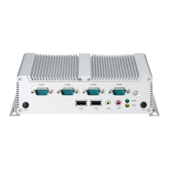
Page 17: Knowing Your Nise 104
Used to connect RS232 compatible devices. Empty antenna holes reserved for installing optional Mini-PCIe Wi-Fi module. COM2 and COM3 RS232/RS422/RS485 Used to connect RS232/422/485 compatible serial devices. Copyright © 2012 NEXCOM International Co., Ltd. All Rights Reserved. NISE 104 User Manual... - Page 18 Dual Gigabit LAN ports to connect the system to a local area network. HDMI CompactFlash Used to connect a high-definition display. Used to insert a CompactFlash card. Copyright © 2012 NEXCOM International Co., Ltd. All Rights Reserved. NISE 104 User Manual...
-
Page 19: Mechanical Dimensions
Chapter 1: Product Introduction Mechanical Dimensions 185.00 194.00 206.00 Copyright © 2012 NEXCOM International Co., Ltd. All Rights Reserved. NISE 104 User Manual... -
Page 20: Chapter 2: Jumpers And Connectors
Chapter 2: Jumpers and Connectors 2: J haPter umPers and onneCtors This chapter describes how to set the jumpers and connectors on the NISE 104 dry environments. A grounding strap is warranted whenever danger of motherboard. static electricity exists. Before You Begin Precautions ▪... -
Page 21: Jumper Settings
(on) and open (off). Two-Pin Jumpers: Open (Left) and Short (Right) Three-Pin Jumpers: Pins 1 and 2 are Short Copyright © 2012 NEXCOM International Co., Ltd. All Rights Reserved. NISE 104 User Manual... -
Page 22: Locations Of The Jumpers And Connectors For Nisb104
Locations of the Jumpers and Connectors for NISB104 The figure below shows the location of the jumpers and connectors. Top View LAN1 USB2 USB1 LAN2 COM1 COM2 COM3 COM4 Copyright © 2012 NEXCOM International Co., Ltd. All Rights Reserved. NISE 104 User Manual... -
Page 23: Bottom View
Chapter 2: Jumpers and Connectors Bottom View JP10 Copyright © 2012 NEXCOM International Co., Ltd. All Rights Reserved. NISE 104 User Manual... -
Page 24: Locations Of The Jumpers And Connectors For Niskio2
Chapter 2: Jumpers and Connectors Locations of the Jumpers and Connectors for NISKIO2 Copyright © 2012 NEXCOM International Co., Ltd. All Rights Reserved. NISE 104 User Manual... -
Page 25: Nisb104
Connector location: JP6 Normal c l e a r (default) CMOS Settings Settings 1-2 On Normal 2-3 On Clear BIOS I_PWRBT# I_PWRBT# NOTE: 1-2 On: default PWRLED_N PWRLED_P Copyright © 2012 NEXCOM International Co., Ltd. All Rights Reserved. NISE 104 User Manual... -
Page 26: Com1 Serial Port
Definition Definition Definition TXD1 DTR1 SP2_DCD SP2_DATA- SP2_TX- DSR1 SP2_RXD SP2_DATA+ SP2_TX+ RTS1 CTS1 SP2_TXD SP2_RX+ SP2_DTR SP2_RX- SP2_DSR SP2_RTS- SP2_RTS SP2_RTS+ SP2_CTS SP2_CTS+ SP2_RI SP2_CTS- Copyright © 2012 NEXCOM International Co., Ltd. All Rights Reserved. NISE 104 User Manual... -
Page 27: Com3 Serial Port
Definition Definition Definition TXD4 DTR4 SP3_DCD SP3_DATA- SP3_TX- DSR4 SP3_RXD SP3_DATA+ SP3_TX+ RTS4 CTS4 SP3_TXD SP3_RX+ SP3_DTR SP3_RX- SP3_DSR SP3_RTS- SP3_RTS SP3_RTS+ SP3_CTS SP3_CTS+ SP3_RI SP3_CTS- Copyright © 2012 NEXCOM International Co., Ltd. All Rights Reserved. NISE 104 User Manual... -
Page 28: External I/O Interfaces - Rear Panel
Connector location: CN4A (DVI) and CN4B (VGA) Definition Definition Definition TX2+ VIN+ DDC_CLK DDC_DATA VSYNC_VGA TX1- TX1+ DVI_VCC(+5V) HotPlugDet TX0- TX0+ DDCCLK_VGA DDCDATA_VGA TXCLK+ TXCLK- GREEN BLUE HSYNC_VGA VGADET CHASSIS_GND CHASSIS_GND Copyright © 2012 NEXCOM International Co., Ltd. All Rights Reserved. NISE 104 User Manual... -
Page 29: Hdmi
Connector location: USB1 Definition Definition Definition Definition HDMI_DATA2_P Data 0- HDMI_DATA2_N HDMI_DATA1_P Data 0+ HDMI_DATA1_N Data 1- HDMI_DATA0_P Data 1+ HDMI_DATA0_N HDMI_CLK_P HDMI_CLK_N HDMI_CTRL_CLK HDMI_CTRL_DATA HDMI_VCC5 HDMI_HPD_R Copyright © 2012 NEXCOM International Co., Ltd. All Rights Reserved. NISE 104 User Manual... -
Page 30: Usb2/3 Ports
No link Data 3+ Status Flashing Yellow Data activity No activity Definition Definition LAN1_MDI0P LAN1_MDI0N LAN1_MDI1P LAN1_MDI1N LAN1TCT LAN1TCTG LAN1_MDI2P LAN1_MDI2N LAN1_MDI3P LAN1_MDI3N LAN1_LEDACT# LAN1_ACTPW LAN1_LINK LAN1_LINK1G# Copyright © 2012 NEXCOM International Co., Ltd. All Rights Reserved. NISE 104 User Manual... -
Page 31: Lan2 Port
Status Flashing Yellow Data activity +12V No activity CPUFANIN(CPU_FAN_SPEED) CPUFANOUT(CPU_FAN_PWM) Definition Definition LAN2_MDI0P LAN2_MDI0N LAN2_MDI1P LAN2_MDI1N LAN2TCT LAN2TCTG LAN2_MDI2P LAN2_MDI2N LAN2_MDI3P LAN2_MDI3N LAN2_LEDACT# LAN2_ACTPW LAN2_LINK LAN2_LINK1G# Copyright © 2012 NEXCOM International Co., Ltd. All Rights Reserved. NISE 104 User Manual... -
Page 32: Dc Input/Output Connector
Connector type: 1x4 JST, 4-pin, 2.5mm pitch Connector type: 2x5 10-pin header, 2.0mm pitch Connector location: CN2 Connector location: JP9 Definition Definition Definition Definition SIO_GPO24(Pin58) SIO_GPI20(Pin52) SIO_GPO25(Pin59) SIO_GPI21(Pin54) SIO_GPO26(Pin60) SIO_GPI22(Pin56) SIO_GPO27(Pin61) SIO_GPI23(Pin57) Copyright © 2012 NEXCOM International Co., Ltd. All Rights Reserved. NISE 104 User Manual... -
Page 33: Keyboard/Mouse Connector
KBMSVCC KBMSVCC LKBDAT LMDAT LKBCLK LMCLK Definition Definition VCC5 VCC5 I_USBN5 I_USBN4 I_USBP5 I_USBP4 I_USBOC#45 VCC3 HDD_LED_PWR POWER_LED_PWR HDD_LED_N PWR_LED_N CODEC_HDASYNC CODEC_HDASDO CODEC_HDARST# CODEC_HDABCLK I_SPKR I_HDASDI0 Copyright © 2012 NEXCOM International Co., Ltd. All Rights Reserved. NISE 104 User Manual... -
Page 34: Pwr_Bt/Ret_Bt/Led/Sm Bus Pin Header
Connector location: JP8 Connector location: JP4 Definition Definition Definition PWR_LED_N PWR_LED_P LAN1_ACTPW LAN1_LEDACT# SATA_LED# SATA_LED_P LAN1_LINK1G# SMB_C SMB_D LAN1_LINK 3VSB PM_SLP_S3 PSON POWER BOTTOM RESET BOTTOM Copyright © 2012 NEXCOM International Co., Ltd. All Rights Reserved. NISE 104 User Manual... -
Page 35: Lan2 Led
Connector type: 2x2 4-pin header, 2.0mm pitch Connector type: 1x6 6-pin header, 2.0mm pitch Connector location: JP5 Connector location: J2 Definition LAN2_ACTPW LAN2_LEDACT# LAN2_LINK1G# LAN2_LINK Definition Definition Data 6- Data 6+ Copyright © 2012 NEXCOM International Co., Ltd. All Rights Reserved. NISE 104 User Manual... -
Page 36: Sata Connector
Connector type: Standard Serial ATAII 7P (1.27mm, SATA-M-180) Connector type: 1x2 JST, 2-pin header, 2.5mm pitch Connector location: CN6 Connector location: J4 Definition Definition SATA_TXP0_C SATA_TXN0_C SATA_RXN0_C SATA_RXP0_C Copyright © 2012 NEXCOM International Co., Ltd. All Rights Reserved. NISE 104 User Manual... -
Page 37: Sim Card Connector
3.5G Line-out Pin Header Connector location: CN7 Connector type: 1x3 3-pin header, 2.54mm pitch Connector location: JP2 Definition Definition Definition UIM_PWR UIM_RESET LOUT_RL UIM_CLK LOUT_RR UIM_VPP UIM_DATA ANGND Copyright © 2012 NEXCOM International Co., Ltd. All Rights Reserved. NISE 104 User Manual... -
Page 38: Cfast Con
Connector location: CN9 Connector location: JP3 Definition Definition Definition MIC_RL SATA_TXP1 MIC_RR SATA_TXN1 ANGND SATA_RXN1 SATA_RXP1 CFAST_ACCESS PC10 PC11 PC12 PC13 +3.3V PC14 +3.3V PC15 PC16 PC17 Copyright © 2012 NEXCOM International Co., Ltd. All Rights Reserved. NISE 104 User Manual... -
Page 39: Mini-Pcie Slot
Definition Definition PCIEWAKE# +3VSB +1.5V SMBCLK +1.5V PCIETX0- SMBDATA CLKREQ# PCIETX0+ USB_D- REF CLK- USB_D+ REF CLK+ +3VSB +3VSB Disable# RST# +1.5V PCIERX0- +3VSB PCIERX0+ +3VSB Copyright © 2012 NEXCOM International Co., Ltd. All Rights Reserved. NISE 104 User Manual... -
Page 40: Niskio2
Connector location: JP1 Definition Definition Definition VCC5 VCC5 I_USBN4 I_USBN5 OUT_L I_USBP4 I_USBP5 EXLINEOUT_JD VCC3 I_USBOC#45 OUT_R POWER_LED_PWR HDD_LED_PWR PWR_LED_N HDD_LED_N CODEC_HDASDO CODEC_HDASYNC CODEC_HDABCLK CODEC_HDARST# I_HDASDI0 I_SPKR Copyright © 2012 NEXCOM International Co., Ltd. All Rights Reserved. NISE 104 User Manual... -
Page 41: Line-Out Internal Speaker
Connector type: 1x5 5-pin header, 2.0mm pitch Connector type: 1x4 4-pin header, 2.0mm pitch Connector location: JP3 Connector location: JP2 Definition Definition FRONT_L+ FLIN_L FRONT_L- LIN_JD FRONT_R+ FLIN_R FRONT_R- Copyright © 2012 NEXCOM International Co., Ltd. All Rights Reserved. NISE 104 User Manual... -
Page 42: Usb1~ Usb2 Connector
Connector type: USB port, Type A Connector type: 3.5mm TRS Connector location: CN1 and CN2 Connector location: MIC1 Definition Definition AU_GND VCC5 MIC_OUT-L DATA_N AU_GN DATA_P MIC_JD1 MIC_OUT-R Copyright © 2012 NEXCOM International Co., Ltd. All Rights Reserved. NISE 104 User Manual... -
Page 43: Power Led/ Hdd Led
Chapter 2: Jumpers and Connectors Power LED/ HDD LED HDD Access LED Power Status LED Definition Green Yellow Copyright © 2012 NEXCOM International Co., Ltd. All Rights Reserved. NISE 104 User Manual... -
Page 44: Chapter 3: System Setup
1.With the bottom side of the chassis facing up, remove the mounting screws of the bottom cover and then put them in a safe place for later use. 2.Lift up the cover and remove it from the chassis. Copyright © 2012 NEXCOM International Co., Ltd. All Rights Reserved. NISE 104 User Manual... - Page 45 You will hear a distinctive “click” sound, indicating the module is The gold-plated connector on the edge of the module will almost completely correctly locked into position. disappear inside the socket. SODIMM SODIMM Clip Socket Copyright © 2012 NEXCOM International Co., Ltd. All Rights Reserved. NISE 104 User Manual...
-
Page 46: Installing A Sata Hard Drive
Align the mounting holes of the SATA drive with the mounting holes on the in place. cover. SATA Drive Cover Inner Side of the Cover Outer Side of the Cover Copyright © 2012 NEXCOM International Co., Ltd. All Rights Reserved. NISE 104 User Manual... -
Page 47: Installing A Compactflash Card
1.The CompactFlash slot is located at the rear side of the chassis SATA Data/Power Cable SATA Drive CompactFlash Slot 4.Connect the SATA data/power cable to connectors CN6 and J4 on the motherboard respectively. Copyright © 2012 NEXCOM International Co., Ltd. All Rights Reserved. NISE 104 User Manual... - Page 48 2. Remove the mounting screws on the CompactFlash slot’s cover. 3. Remove the slot’s cover to access the CompactFlash slot. Mounting Screws CompactFlash Slot 4. Fasten the CompactFlash cover after installation. Copyright © 2012 NEXCOM International Co., Ltd. All Rights Reserved. NISE 104 User Manual...
-
Page 49: Installing A Wireless Lan Module
Wireless LAN Module Mini PCI Express Slot Mini PCI Express Slot Copyright © 2012 NEXCOM International Co., Ltd. All Rights Reserved. NISE 104 User Manual... - Page 50 4.Remove the antenna hole covers located at the front panel of the chassis. Antenna Hole Covers Mounting Screws Note: If it is full-size module, please remove this bracket. Copyright © 2012 NEXCOM International Co., Ltd. All Rights Reserved. NISE 104 User Manual...
- Page 51 6.Insert the 2 rings (ring 1 and ring2) onto the antenna jacks Antenna Jack (with long cable) Antenna Jack (with short cable) Ring 1 Ring 2 Copyright © 2012 NEXCOM International Co., Ltd. All Rights Reserved. NISE 104 User Manual...
- Page 52 Chapter 3: System Setup 7.Attach RF cables of the antenna jacks onto the module. 8.Connect an external antenna to the antenna jack. RF Cables Copyright © 2012 NEXCOM International Co., Ltd. All Rights Reserved. NISE 104 User Manual...
-
Page 53: Installing The Sim Card
Installing the SIM Card 1.Slide the SIM card holder to the “OPEN” position. 2.Slide the SIM card into the SIM card holder. SIM Card Holder SIM Card Copyright © 2012 NEXCOM International Co., Ltd. All Rights Reserved. NISE 104 User Manual... -
Page 54: Installing The Sata Dom
3. Move the holder down and then slide it to the “LOCK” position. 1.Locate the SATA connector on the motherboard and remove the screw as marked. SATA Connector Screw Copyright © 2012 NEXCOM International Co., Ltd. All Rights Reserved. NISE 104 User Manual... - Page 55 3.Install the SATA DOM and connect the SATA power cable to the SATA the screw hole. DOM connector on the motherboard. Screw Copper Post 4.Tighten a screw on the top of the copper post. Copyright © 2012 NEXCOM International Co., Ltd. All Rights Reserved. NISE 104 User Manual...
-
Page 56: Installing Wallmount Brackets
Secure with screws Wallmount Bracket Fasten screws to mount the system to the wall Copyright © 2012 NEXCOM International Co., Ltd. All Rights Reserved. NISE 104 User Manual... -
Page 57: Chapter 4: Bios Setup
This chapter describes how to use the BIOS setup program for the NISE 104. The settings made in the setup program affect how the computer per- The BIOS screens provided in this chapter are for reference only and may forms. -
Page 58: Default Configuration
When “u“ appears on the left of a particular field, it indicates that a submenu which contains additional options are available for that field. To display the submenu, move the highlight to that field and press <Enter>. Copyright © 2012 NEXCOM International Co., Ltd. All Rights Reserved. NISE 104 User Manual... -
Page 59: Bios Setup Utility
+/-: Change Opt. F1: General Help F2: Previous Values F3: Optimized Defaults F4: Save & Exit ESC: Exit Version 2.14.1219. Copyright (C) 2011 American Megatrends, Inc. Copyright © 2012 NEXCOM International Co., Ltd. All Rights Reserved. NISE 104 User Manual... -
Page 60: Advanced
F4: Save & Exit F4: Save & Exit ESC: Exit ESC: Exit Version 2.14.1219. Copyright (C) 2011 American Megatrends, Inc. Version 2.14.1219. Copyright (C) 2011 American Megatrends, Inc. Copyright © 2012 NEXCOM International Co., Ltd. All Rights Reserved. NISE 104 User Manual... - Page 61 ESC: Exit Version 2.14.1219. Copyright (C) 2011 American Megatrends, Inc. Version 2.14.1219. Copyright (C) 2011 American Megatrends, Inc. This field is used to enable or disable hyper-threading. Copyright © 2012 NEXCOM International Co., Ltd. All Rights Reserved. NISE 104 User Manual...
-
Page 62: Execute Disable Bit
OS (Windows Server 2003 SP1, Windows XP SP2, SuSE F4: Save & Exit ESC: Exit Linux 9.2, RedHat Enterprise 3 Update 3). Version 2.14.1219. Copyright (C) 2011 American Megatrends, Inc. Copyright © 2012 NEXCOM International Co., Ltd. All Rights Reserved. NISE 104 User Manual... -
Page 63: Usb Configuration
This option configures the Serial ATA drives to use AHCI (Advanced AHCI Host Controller Interface). AHCI allows the storage driver to enable the advanced Serial ATA features which will increase storage performance. Copyright © 2012 NEXCOM International Co., Ltd. All Rights Reserved. NISE 104 User Manual... -
Page 64: Super Io Configuration
Version 2.14.1219. Copyright (C) 2011 American Megatrends, Inc. This field configures the maximum baud rate of the serial port 0, the options are 115200 bps and 921600 bps. Copyright © 2012 NEXCOM International Co., Ltd. All Rights Reserved. NISE 104 User Manual... - Page 65 This field is used to configure the mode of serial port 1 as RS232, RS422, This field configures the maximum baud rate of the serial port 1, the options RS485 or RS485 AUTO. are 115200 bps and 921600 bps. Copyright © 2012 NEXCOM International Co., Ltd. All Rights Reserved. NISE 104 User Manual...
- Page 66 F4: Save & Exit F4: Save & Exit ESC: Exit ESC: Exit Version 2.14.1219. Copyright (C) 2011 American Megatrends, Inc. Version 2.14.1219. Copyright (C) 2011 American Megatrends, Inc. Copyright © 2012 NEXCOM International Co., Ltd. All Rights Reserved. NISE 104 User Manual...
-
Page 67: Chipset
Version 2.14.1219. Copyright (C) 2011 American Megatrends, Inc. Version 2.14.1219. Copyright (C) 2011 American Megatrends, Inc. Setting incorrect field values may cause the system to malfunction. Copyright © 2012 NEXCOM International Co., Ltd. All Rights Reserved. NISE 104 User Manual... -
Page 68: Host Bridge
+/-: Change Opt. F1: General Help F2: Previous Values F3: Optimized Defaults F4: Save & Exit ESC: Exit Version 2.14.1219. Copyright (C) 2011 American Megatrends, Inc. Copyright © 2012 NEXCOM International Co., Ltd. All Rights Reserved. NISE 104 User Manual... - Page 69 Please refer to the following table for the display reference Which will be activated IGFX - Boot Type [DVI] during POST. when a HDMI monitor is connected to NISE 104. Fixed Graphics Memory Size [128MB] This has no effect if external graphics present.
-
Page 70: South Bridge
This section disables Azalia or enables HD Audio. SMBus Controller This section is used to configure SMBus. High Precision Timer This section is used to configure High Precision Event Timer. Copyright © 2012 NEXCOM International Co., Ltd. All Rights Reserved. NISE 104 User Manual... -
Page 71: Boot
Version 2.14.1219. Copyright (C) 2011 American Megatrends, Inc. This field is used to configure the AC power state when power is restored after power failure, the options are Power Off and Power On. Copyright © 2012 NEXCOM International Co., Ltd. All Rights Reserved. NISE 104 User Manual... -
Page 72: Security
This field is used to adjust the boot sequence of the system. Boot Option #1 is the first boot device that the system will boot from, next will be #2 and Sets the user’s password. so forth. Copyright © 2012 NEXCOM International Co., Ltd. All Rights Reserved. NISE 104 User Manual... -
Page 73: Save & Exit
To exit the Setup utility without saving the changes, select this field then press <Enter>. You may be prompted to confirm again before exiting. You can also press <ESC> to exit without saving the changes. Copyright © 2012 NEXCOM International Co., Ltd. All Rights Reserved. NISE 104 User Manual... - Page 74 <Enter>. Launch EFI Shell from filesystem device To launch EFI shell from a filesystem device, select this field and press <Enter>. Copyright © 2012 NEXCOM International Co., Ltd. All Rights Reserved. NISE 104 User Manual...
-
Page 75: Appendix A: Gpi/O Programming Guide
IO base address : A00h This appendix provides definitions and its default setting for the Digital I/O Bit0 : GPI20 pins in the NISE 104. The pin definition is shown is the following table: Bit1 : GP I21 Bit2 : GP I22... -
Page 76: Appendix B: Watchdog Timer
Users can select second or minute. Step3. See “TimeCountWDT” procedure #Set Watchdog Timer Time-out Value. Users can set time-out value. Step4: See ExitSetup procedure #Exit Setup Environment Copyright © 2012 NEXCOM International Co., Ltd. All Rights Reserved. NISE 104 User Manual... - Page 77 07h ;Select logical device for Watch Dog. =============================================== 2fh, al SetupWDT ENDP =============================================== TimeBaseWDT PROC al, 72h 2eh, al al, 10h ;Set WDT reset upon PWROK Copyright © 2012 NEXCOM International Co., Ltd. All Rights Reserved. NISE 104 User Manual...
-
Page 78: Appendix C: Power Consumption
Microsoft Wired Keyboard 600 Sys #1 Sys #1 Mouse Microsoft Basic Optical Mouse +12V +24V Full-Loading Mode 1.81A 0.96A Total 21.72W 23.04W Standby S1Mode 0.84A 0.45A Total 10.08W 10.8W Copyright © 2012 NEXCOM International Co., Ltd. All Rights Reserved. NISE 104 User Manual...
Need help?
Do you have a question about the NISE 104 and is the answer not in the manual?
Questions and answers