
Related Manuals for Nexcom VTC 1011 Series


Summary of Contents for Nexcom VTC 1011 Series
- Page 1 NEXCOM International Co., Ltd. Mobile Computing Solutions Vehicle Telematics Computer VTC 1011 Series User Manual NEXCOM International Co., Ltd. www.nexcom.com Published January 2023...
-
Page 2: Table Of Contents
Multi Port ..................16 VTC 1011-C2VK Rear View ..............2 COM 1 Port ..................16 VTC 1011 Series Overview ..............3 VGA Connector .................17 VTC 1011 Series Key Features ..............3 Copyright © 2023 NEXCOM International Co., Ltd. All Rights Reserved. VTC 1011 Series User Manual... - Page 3 GPI Setting ....................53 Chapter 4: System Setup GPO Setting ..................54 Removing the Chassis Cover ..............33 Digital Input ..................55 Installing a SO-DIMM ................35 Digital Output ..................56 Copyright © 2023 NEXCOM International Co., Ltd. All Rights Reserved. VTC 1011 Series User Manual...
- Page 4 Entering BIOS Menu ................66 POE 54V Setting ...................66 Appendix G: Vehicle Display Setup Entering BIOS Menu ................68 Display Control Setting .................68 Appendix H: Power Consumption Copyright © 2023 NEXCOM International Co., Ltd. All Rights Reserved. VTC 1011 Series User Manual...
-
Page 5: Preface
Acknowledgements The product(s) described in this manual complies with all applicable The VTC 1011 series is a trademark of NEXCOM International Co., Ltd. All European Union (CE) directives if it has a CE marking. For computer systems other product names mentioned herein are registered trademarks of their to remain CE compliant, only CE-compliant parts may be used. -
Page 6: Rohs Compliance
(Cr6+) < 0.1% or 1,000ppm, Polybrominated biphenyls (PBB) < 0.1% or 1,000ppm, and Polybrominated diphenyl Ethers (PBDE) < 0.1% or 1,000ppm. In order to meet the RoHS compliant directives, NEXCOM has established an engineering and manufacturing task force to implement the introduction of green products. -
Page 7: Warranty And Rma
“NEXCOM RMA Service Form” for the RMA number apply process. ▪ If RMA goods can not be repaired, NEXCOM will return it to the customer without any charge. ▪ Customers can send back the faulty products with or without accessories (manuals, cable, etc.) and any components from the card, such as CPU... - Page 8 ESD protection by wearing an antistatic wrist strap and attaching it to a metal part of the computer chassis. viii Copyright © 2023 NEXCOM International Co., Ltd. All Rights Reserved. VTC 1011 Series User Manual...
-
Page 9: Safety Information
Discard used batteries according to the manufacturer’s instructions. can damage the soft metal or plastic parts of the connectors. Copyright © 2023 NEXCOM International Co., Ltd. All Rights Reserved. VTC 1011 Series User Manual... -
Page 10: Safety Precautions
RECOMMENDED BY THE MANUFACTURER. DISCARD USED BATTERIES ACCORDING TO THE MANUFACTURER’S INSTRUCTIONS. 10. All cautions and warnings on the equipment should be noted. Copyright © 2023 NEXCOM International Co., Ltd. All Rights Reserved. VTC 1011 Series User Manual... -
Page 11: Technical Support And Assistance
Preface Technical Support and Assistance Conventions Used in this Manual 1. For the most updated information of NEXCOM products, visit NEXCOM’s Warning: website at www.nexcom.com. Information about certain situations, which if not observed, can cause personal injury. This will prevent injury to yourself 2. -
Page 12: Global Service Contact Information
Tel: +886-2-8226-7786 Tel: +886-2-8976-3077 Beitun District, Fax: +886-2-8226-7782 Email: sales@diviotec.com Taichung City, 406, Taiwan, R.O.C. Email: services@tmrtek.com www.diviotec.com Tel: +886-4-2249-1179 www.tmrtek.com Fax: +886-4-2249-1172 Email: jacobhuang@nexaiot.com www.nexaiot.com Copyright © 2023 NEXCOM International Co., Ltd. All Rights Reserved. VTC 1011 Series User Manual... - Page 13 LongGang District, 4-11-5, Shiba Minato-ku, ShenZhen, 518112, China Tokyo, 108-0014, Japan Tel: +86-755-8364-7768 Tel: +81-3-5419-7830 Fax: +86-755-8364-7738 Fax: +81-3-5419-7832 Email: steveyang@nexcom.com.tw Email: sales@nexcom-jp.com www.nexcom.cn www.nexcom-jp.com xiii Copyright © 2023 NEXCOM International Co., Ltd. All Rights Reserved. VTC 1011 Series User Manual...
-
Page 14: Package Contents
PE Bag 330x320x0.08mm 5061100212X00 Wi-Fi Module Sponge for VTC 1011 32.3x15mm 1.8T EPDM E4308 1.5T+3M9888T Black 6030000286X00 Multi Cable for VTC 1011 DB15 to DB9Fx2/DB9Mx1 L=300mm Copyright © 2023 NEXCOM International Co., Ltd. All Rights Reserved. VTC 1011 Series User Manual... -
Page 15: Ordering Information
& 1 x (RS-232 (Tx/Rx)/RS-422/485), ultraONE+ technology support, 1 x CAN 2.0B, 4 x DI & 4 x DO, 2 x USB 2.0, 1 x Line-out, 1 x Mic-in Copyright © 2023 NEXCOM International Co., Ltd. All Rights Reserved. VTC 1011 Series User Manual... -
Page 16: Chapter 1: Product Introduction
Ports Ports DC Input Multi Port COM1 Mic-in Slot Reset COM2 HDMI PoE Status DC Output Line-out LEDs Indicators Antenna Holes Antenna Holes Antenna Connector Copyright © 2023 NEXCOM International Co., Ltd. All Rights Reserved. VTC 1011 Series User Manual... -
Page 17: Physical Features
Ports DC Input Multi Port COM1 Mic-in Slot Reset COM2 HDMI PoE Status DC Output Line-out LEDs Indicators ultraONE+ Antenna Holes Antenna Holes Antenna Connector Copyright © 2023 NEXCOM International Co., Ltd. All Rights Reserved. VTC 1011 Series User Manual... -
Page 18: Vtc 1011 Series Overview
VMD 2003 (VTC 1011-C2VK only) management and patching system. ▪ Wide range DC input from 9~36V ▪ Wide operating temperature -40°C~70°C ▪ Certified by CE/FCC/E13 Copyright © 2023 NEXCOM International Co., Ltd. All Rights Reserved. VTC 1011 Series User Manual... -
Page 19: Hardware Specifications
▪ 1 x Reset button Storage temperatures: -45°C to 85°C ▪ 2 x LEDs for PoE status Damp Heat Test per EN60068-2-30 ▪ 2 x RJ45 PoE Copyright © 2023 NEXCOM International Co., Ltd. All Rights Reserved. VTC 1011 Series User Manual... - Page 20 ▪ Shock: MIL-STD-810G, 516.6 Procedure I, trucks and semi-trailers=40g Crash hazard: Procedure V, ground equipment=75g Standards/Certifications ▪ CE approval ▪ FCC Class A ▪ E13 mark Copyright © 2023 NEXCOM International Co., Ltd. All Rights Reserved. VTC 1011 Series User Manual...
-
Page 21: Mechanical Dimensions
Chapter 1: Product Introduction Mechanical Dimensions VTC 1011-C2K Ø4.00*2 Ø4.00 219.40 185.00 172.10 Copyright © 2023 NEXCOM International Co., Ltd. All Rights Reserved. VTC 1011 Series User Manual... -
Page 22: Vtc 1011-C2Vk
Chapter 1: Product Introduction VTC 1011-C2VK Ø4.00*2 Ø4.00 219.40 185.00 172.10 Copyright © 2023 NEXCOM International Co., Ltd. All Rights Reserved. VTC 1011 Series User Manual... -
Page 23: Connector Numbering
The following diagrams indicate the numbers of the connectors. Use these numbers to locate the connectors’ respective pinout assignments on chapter 2 of the manual. VTC 1011-C2K Front View VTC 1011-C2K Rear View Copyright © 2023 NEXCOM International Co., Ltd. All Rights Reserved. VTC 1011 Series User Manual... -
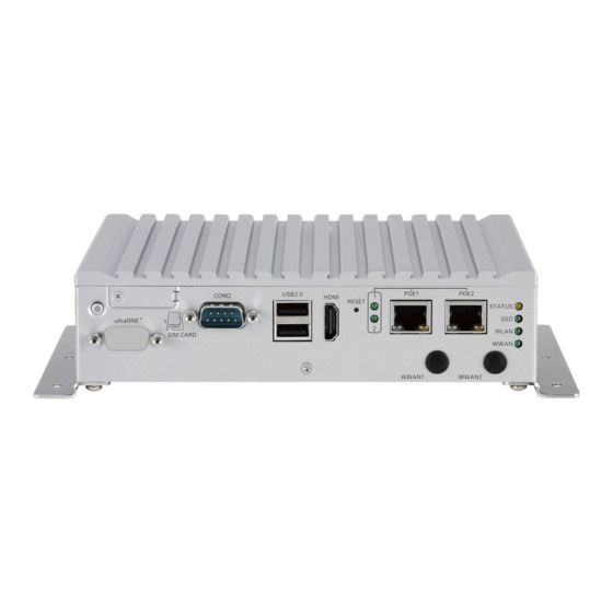
Page 24: Vtc 1011-C2Vk Front View
Chapter 1: Product Introduction VTC 1011-C2VK Front View VTC 1011-C2VK Rear View Copyright © 2023 NEXCOM International Co., Ltd. All Rights Reserved. VTC 1011 Series User Manual... -
Page 25: Chapter 2: External Connectors Pinout Description
Connector number: 1 Connector number: 2 SIM1 Definition Definition Definition Definition PWRBT_IN# UIM1_PWR UIM1_RST UIM1_CLK PWRBT_IN# LED_A LED_C UIM1_DAT SIM2 Definition Definition UIM2_PWR UIM2_RST UIM2_CLK UIM2_DAT Copyright © 2023 NEXCOM International Co., Ltd. All Rights Reserved. VTC 1011 Series User Manual... -
Page 26: Com 2 Port
USB1 Pin Connector Definition Definition Definition Definition Definition DCD_2 RXD_2 DATA1- TXD_2 DTR_2 DATA1+ DSR_2 RTS_2 CTS_2 USB2 Pin Connector Definition RI/PW Definition Definition DATA- DATA+ Copyright © 2023 NEXCOM International Co., Ltd. All Rights Reserved. VTC 1011 Series User Manual... -
Page 27: Hdmi Connector
HDMI Connector Reset Button Connector number: 5 Connector number: 6 Definition Definition Definition HDMI_TX2P_L HDMI_TX2N_L HDMI_TX1P_L RESET HDMI_TX1N_L HDMI_TX0P_L HDMI_TX0N_L HDMI_CLK_P_L HDMI_CLK_N_L HDMI_SCL HDMI_SDA HDMI_P5V HDMI_HPD Copyright © 2023 NEXCOM International Co., Ltd. All Rights Reserved. VTC 1011 Series User Manual... -
Page 28: Poe Led Indicators
Connector number: 8 LINK Description Definition Definition PoE1 Light On: Active MDI0P MDI0N PoE2 Light On: Active MDI1P MDI2P MDI2N MDI1N MDI3P MDI3N LED1- LED1+ LED2- LED2+ Copyright © 2023 NEXCOM International Co., Ltd. All Rights Reserved. VTC 1011 Series User Manual... -
Page 29: Led Indicators
Definition Definition Status Programmable. Power On: Green USB_DATA- VMD_UGND Light On: HDD/SSD Active ultraONE- LCD_PWR_BTN WLAN Blinking: Active 24V_VM203 USB_DATA+ WWAN Blinking: Active ultraONE+ VM_GND Copyright © 2023 NEXCOM International Co., Ltd. All Rights Reserved. VTC 1011 Series User Manual... -
Page 30: Dc Power Input
Connector number: 11 Connector number: 12 Definition Definition Definition GND_IN PUSH_BTN_RSTIN# PUSH_BTN_SLEPIN# V_IN IGNITION **RS-232 TX **RS-232 RX PUSH_BTN_PWRIN# +V12S **Reserved for VTK62B in the future. Copyright © 2023 NEXCOM International Co., Ltd. All Rights Reserved. VTC 1011 Series User Manual... -
Page 31: Multi Port
Definition Definition COM3_RX_TX+_R GPI_0 DCD_2 RXD_2 GPI_3 GPO_2 TXD_2 DTR_2 MCU_CAN1_H COM3_DCD#_TX-_R DSR_2 COM3_DTR#_RX-_R GPI_2 RTS_2 CTS_2 GPO_1 IOC_GND RI/PW COM3_TX_RX+_R GPI_1 GPO_0 GPO_3 MCU_CAN1_L Copyright © 2023 NEXCOM International Co., Ltd. All Rights Reserved. VTC 1011 Series User Manual... -
Page 32: Vga Connector
Connector number: 15 Connector number: 16 Definition Definition Definition Definition GREEN Mic-in (Left Channel) BLUE CH7517_SPC Detect M_DET VGA_GND VGA_GND VGA_VCC CH7517_SPD VGA_DAT VGA_HS VGA_VS VGA_CLK Copyright © 2023 NEXCOM International Co., Ltd. All Rights Reserved. VTC 1011 Series User Manual... -
Page 33: Line-Out Connector
Chapter 2: External Connectors Pinout Description Line-out Connector Connector number: 17 Definition Definition Mic-in (Left Channel) Detect Right Channel Copyright © 2023 NEXCOM International Co., Ltd. All Rights Reserved. VTC 1011 Series User Manual... -
Page 34: Chapter 3: Jumpers And Connectors
Static electricity can damage many of the electronic ▪ Use correct screws and do not over tighten screws. components. Humid environments tend to have less static electricity than Copyright © 2023 NEXCOM International Co., Ltd. All Rights Reserved. VTC 1011 Series User Manual... -
Page 35: Jumper Settings
(on) and open (off). Two-Pin Jumpers: Open (Left) and Short (Right) Three-Pin Jumpers: Pins 1 and 2 are Short Copyright © 2023 NEXCOM International Co., Ltd. All Rights Reserved. VTC 1011 Series User Manual... -
Page 36: Locations Of The Jumpers And Connectors
Locations of the Jumpers and Connectors This chapter lists the location and pinout assignment of the jumpers and connectors on the VTC 1011 series motherboard. Top View SW1 SW2 CN10 Copyright © 2023 NEXCOM International Co., Ltd. All Rights Reserved. VTC 1011 Series User Manual... -
Page 37: Connector Pin Definitions
Don’t Care SW1.3 Pull up VCC Don’t Care SW2.3 Pull up VCC Don’t Care SW1.4 Pull up VCC Don’t Care SW2.4 Pull up VCC Don’t Care Copyright © 2023 NEXCOM International Co., Ltd. All Rights Reserved. VTC 1011 Series User Manual... -
Page 38: Rs485 Pull High Switch
RS485 Output Pull High 1 ~ 2 ON CAN Bus with terminal 1 ~ 2 OFF RS485 Output NC 1 ~ 2 OFF CAN Bus without terminal Copyright © 2023 NEXCOM International Co., Ltd. All Rights Reserved. VTC 1011 Series User Manual... -
Page 39: Clear Cmos
Chapter 3: Jumpers and Connectors Clear CMOS Connector type: DIP switch Connector location: SW6 Definition 1 ~ 2 ON Clear CMOS/ME 1 ~ 2 OFF Normal Copyright © 2023 NEXCOM International Co., Ltd. All Rights Reserved. VTC 1011 Series User Manual... -
Page 40: Com1 Ri/Power Select
Definition 3 ~ 4 Short Support UART RI GPS_BAT GPS_LED# 1 ~ 3 Short Support +5V GPS_TX GPS_RX 3 ~ 5 Short Support +12V VCC3_GPS Copyright © 2023 NEXCOM International Co., Ltd. All Rights Reserved. VTC 1011 Series User Manual... -
Page 41: Gps Battery Connector
Connector type: 1x2 2-pin header Connector type: Standard Serial ATA 7P (1.27mm, SATA-M-180) Connector location: J3 Connector location: CN8 Definition Definition Definition SATA_TXP0 RTC_BAT SATA_TXN0 SATA_RXN0 SATA_RXP0 Copyright © 2023 NEXCOM International Co., Ltd. All Rights Reserved. VTC 1011 Series User Manual... -
Page 42: Sata Power Connector
Connector type: 1x2 2-pin header Connector type: 1x6 6-pin header Connector location: J4 Connector location: J6 Definition Definition Definition VCC5 USB2_POWER USBHUB_2N_C USBHUB_2PC WLAN1_LED WLAN1_DIS Copyright © 2023 NEXCOM International Co., Ltd. All Rights Reserved. VTC 1011 Series User Manual... -
Page 43: Ultraone+ Internal Io Connector
BKLTCL_CH7511 EDP_TX1N USBHUB_4N_C RST_CH7511 DPC1_VDEN EDP_TX0P DPC1_BKLTEN EDP_TX0N LVDS_DET# LAN_MONITOR_DET CH7511_GPIO3 EDP_AUX_P USBHUB_3P_C CH7511_GPIO1 CH7511_GPIO2 EDP_AUX_N USBHUB_3N_C CH7511_GPIO0 VCC3 SMB_CLK 12VSB VCC5 SMB_DATA 12VSB DPC1_HPD Copyright © 2023 NEXCOM International Co., Ltd. All Rights Reserved. VTC 1011 Series User Manual... -
Page 44: Rtc Battery Connector
Connector location: JP9 Definition Definition 3 ~ 4 Short Support UART RI RTC_BAT 1 ~ 3 Short Support +5V 3 ~ 5 Short Support +12V Copyright © 2023 NEXCOM International Co., Ltd. All Rights Reserved. VTC 1011 Series User Manual... -
Page 45: Cn9 Wi-Fi Led Select & Cn10 Audio Pcm Tx, Rx Switch
Special WWAN Module PCM 2, 3 ON (MC7430) Definition 5 ON Normal Wi-Fi Module LED 6 OFF (Default) 5 OFF Special Wi-Fi Module LED 6 ON (Inverse) Copyright © 2023 NEXCOM International Co., Ltd. All Rights Reserved. VTC 1011 Series User Manual... -
Page 46: Mini-Pcie For Pcie/Usb/Msata
USB_D- REFCLK- USB_D+ REFCLK+ +V3.3_MINI_3 +V3.3_MINI_3 MINICARD3_DIS# WLAN_RESET# +V1.5S_MINI_3 SATA_RXP0_C +V3.3_MINI_3 SATA_RXN0_C CTRL0 +V3.3_MINI_3 When CTRL=0, CN9 is mSATA. When CTRL=1, CN9 is PCIe device. Copyright © 2023 NEXCOM International Co., Ltd. All Rights Reserved. VTC 1011 Series User Manual... -
Page 47: Mini-Pcie For Usb (Wwan)
+V3.3_MINI1 USB3_TXN_R UIMB_PWR USB3_TXP_R UIMB_DAT USB_0N_T VCC_MSM26_DIG UIMB_CLK USB_0P_T UIMB_RST +V3.3_MINI1 +V3.3_MINI1 WWAN_LED# MCU_TX2 MCU_RX2 3.5G_DIS#_L PCM_CLK 3.5G_RST# PCM_RX_SW USB3_RXN_R +V3.3_MINI1 PCM_TX_SW USB3_RXP_R PCM_SYNC +V3.3_MINI1 Copyright © 2023 NEXCOM International Co., Ltd. All Rights Reserved. VTC 1011 Series User Manual... -
Page 48: Chapter 4: System Setup
Remove these screws and nuts and put them in a safe place for later use. Left View Front View Rear View Copyright © 2018 NEXCOM International Co., Ltd. All Rights Reserved. VTC 1011 Series User Manual... - Page 49 Chapter 4: System Setup Bottom View Copyright © 2018 NEXCOM International Co., Ltd. All Rights Reserved. VTC 1011 Series User Manual...
-
Page 50: Installing A So-Dimm
The contact fingers on the edge of the module will fasten screws into the mounting holes to secure the module. almost completely disappear inside the socket. Copyright © 2018 NEXCOM International Co., Ltd. All Rights Reserved. VTC 1011 Series User Manual... -
Page 51: Installing A Wlan Module (Full Mini-Pcie)
2. Connect the inner cable from the Wi-Fi module to the reserved USB wafer (J6) connector. Copyright © 2018 NEXCOM International Co., Ltd. All Rights Reserved. VTC 1011 Series User Manual... -
Page 52: Installing A J1708/J1939 Module
2. Connect the inner cable from the GPS module to the GPS wafer (J2) connector. connector. 3. Please remove the ultraONE+ connector bracket and insert the DB9 connector for the module. Copyright © 2018 NEXCOM International Co., Ltd. All Rights Reserved. VTC 1011 Series User Manual... -
Page 53: Installing An Ssd/Hdd Drive
Align the SSD/HDD mounting holes with the mounting holes on the drive bay, and use the provided gaskets and screws to secure the hard drive in place. Copyright © 2018 NEXCOM International Co., Ltd. All Rights Reserved. VTC 1011 Series User Manual... - Page 54 Chapter 4: System Setup 3. Insert the drive bay back in the SSD/HDD slot and tighten the screws to secure it in place. Copyright © 2018 NEXCOM International Co., Ltd. All Rights Reserved. VTC 1011 Series User Manual...
-
Page 55: Inserting The Sim Card
1. Remove the SIM card cover on the front panel and insert two SIM cards. Please note the SIM card installation direction as printed on the chassis. Copyright © 2018 NEXCOM International Co., Ltd. All Rights Reserved. VTC 1011 Series User Manual... -
Page 56: Appendix A: Software Demo Utility For I/O Ports Of Function Control
NEXCOM’s software demo utility enables users to test and control different I/O port functions on the VTC 1011 series. This document shows how to use the utility. There are also source code files of the utility in the CD. Users can refer to the source codes to develop their applications. -
Page 57: Config1
Enables or disables the WWAN function on CN10 Mini-PCIe socket. Enables or disables the WWAN wakeup function on CN10 Mini-PCIe socket. The setting can also be cleared by the Set button. Copyright © 2023 NEXCOM International Co., Ltd. All Rights Reserved. VTC 1011 Series User Manual... -
Page 58: Config2
Selects SIM Card1 or SIM Card2 for SIM card configuration. The setting can also be cleared by the Set button. 2.2 GPI Defines GPI port as High or Low. Copyright © 2023 NEXCOM International Co., Ltd. All Rights Reserved. VTC 1011 Series User Manual... - Page 59 Defines Program LED as ON or OFF. 2.4 Wake On LAN Enables or disables the Wake On LAN function. 2.5 External 12V Enables or disables the External 12V function. Copyright © 2023 NEXCOM International Co., Ltd. All Rights Reserved. VTC 1011 Series User Manual...
-
Page 60: Config3
Enables or disables the Alarm wake up function. The timer setting of Alarm 3.1 Low Battery Voltage Protection Timer can be configured. Sets the Low Battery Voltage Protection Startup/Shutdown voltage level during 12V/24V. Copyright © 2023 NEXCOM International Co., Ltd. All Rights Reserved. VTC 1011 Series User Manual... -
Page 61: G-Sensor
Selects the registers inside G-Sensor to read or write the data. 4.2 Register Table Shows the value of all registers in G-Sensor, once the Refresh Button is pressed. Copyright © 2023 NEXCOM International Co., Ltd. All Rights Reserved. VTC 1011 Series User Manual... -
Page 62: Tracker
Server IP: 59.120.0.36 (default). It can be adjusted based on users’ situation. Server Port: 1200 (default). It can be adjusted based on users’ situation. Note: This function is only supported by the VIOB-WWAN-HDA0 or VIOB-WWAN-HAA0 module. Copyright © 2023 NEXCOM International Co., Ltd. All Rights Reserved. VTC 1011 Series User Manual... - Page 63 If Tracker function is “Enable” and Tracker Mode is “Continue”, following information will be sent to server, based on the interval time defined in Send Period. Copyright © 2023 NEXCOM International Co., Ltd. All Rights Reserved. VTC 1011 Series User Manual...
-
Page 64: Poe
Press the Save button to show the PoE related information. Note: It is required to press the Save Button for saving the settings made in the Utility. Copyright © 2023 NEXCOM International Co., Ltd. All Rights Reserved. VTC 1011 Series User Manual... -
Page 65: Event
Appendix A: Software Demo Utility for I/O Ports of Function Control 7. Event Shows the Event of VTC 1011, such as lower voltage event. Copyright © 2023 NEXCOM International Co., Ltd. All Rights Reserved. VTC 1011 Series User Manual... -
Page 66: Appendix B: Gps Feature
RTC crystal Built-in standard: “Road vehicles – Environmental conditions and testing for Noise figure Extra LNA for lowest noise figure (NEO-M8N) electrical and electronic equipment”. Copyright © 2018 NEXCOM International Co., Ltd. All Rights Reserved. VTC 1011 Series User Manual... - Page 67 COM Port for GPS: COM 4 Baud Rate: 9600 Digital I/O Configurable timepulse 1 EXTINT input for Wakeup Timepulse Configurable 0.25 Hz to 10 MHz Protocols NMEA, UBX binary, RTCM Copyright © 2018 NEXCOM International Co., Ltd. All Rights Reserved. VTC 1011 Series User Manual...
-
Page 68: Appendix D: Signal Connection Of Gpi/Gpo
GPI (SW1) GPI_0 GPI_1 Pull up VCC GPI_2 GPI_3 Don’t Care GPO_0 GPO_1 GPO_2 GPO_3 Default Settings: IOC_GND GPI (SW1) SW1.1 ~ SW1.4 Pull up VCC Copyright © 2018 NEXCOM International Co., Ltd. All Rights Reserved. VTC 1011 Series User Manual... -
Page 69: Gpo Setting
Appendix D: Signal Connection of GPI/GPO GPO Setting Connector location: SW2 GPO (SW2) Pull up VCC Don’t Care Default Settings: GPO (SW2) SW2.1 ~ SW2.4 Pull up VCC Copyright © 2018 NEXCOM International Co., Ltd. All Rights Reserved. VTC 1011 Series User Manual... -
Page 70: Digital Input
GPI_3 GPI_1 GPI_2 GPI_3 External power Resistor External External Port Port Switch Register Switch Register ON (Short) ON (Short) OFF (Open) OPEN OFF (Open) HIGH Copyright © 2018 NEXCOM International Co., Ltd. All Rights Reserved. VTC 1011 Series User Manual... -
Page 71: Digital Output
The figure below shows how to connect an external input source to one of the output channels. the output channels. GPO_0 GPO_0 GPO_1 GPO_1 GPO_2 GPO_2 GPO_3 External power GPO_3 Resistor Port Port Register Register HIGH OPEN Copyright © 2018 NEXCOM International Co., Ltd. All Rights Reserved. VTC 1011 Series User Manual... - Page 72 The multiport consists of a 15-pin connector and multiple output connectors. The tables in this appendix list the pin signals of the P1 connector and its corresponding pin signals to the output connectors. 300±10 Copyright © 2018 NEXCOM International Co., Ltd. All Rights Reserved. VTC 1011 Series User Manual...
-
Page 73: P1 Connector Pinout
P1 Pin P2 Pin Definition COM3_RX_TX+_R GPI_0 COM3_DCD#_TX-_R GPI_3 GPO_2 COM3_RX_TX+_R MCU_CAN1_H COM3_DCD#_TX-_R COM3_TX_RX+_R COM3_DTR#_RX-_R GPI_2 COM3_DTR#_RX-_R GPO_1 IOC_GND IOC_GND COM3_TX_RX+_R GPI_1 GPO_0 GPO_3 MCU_CAN1_L Copyright © 2018 NEXCOM International Co., Ltd. All Rights Reserved. VTC 1011 Series User Manual... -
Page 74: Gpio Connector
Connector location: P4 P1 Pin P3 Pin Definition P1 Pin P4 Pin Definition GPI_0 IOC_GND GPI_1 MCU_CAN1_H GPI_2 MCU_CAN1_L GPI_3 GPO_0 GPO_1 GPO_2 GPO_3 IOC_GND Copyright © 2018 NEXCOM International Co., Ltd. All Rights Reserved. VTC 1011 Series User Manual... -
Page 75: Appendix E: Vehicle Power Management Setup
F4: Save & Exit F4: Save & Exit ESC: Exit ESC: Exit Version 2.17.1249. Copyright (C) 2017 American Megatrends, Inc. Version 2.17.1249. Copyright (C) 2017 American Megatrends, Inc. Copyright © 2018 NEXCOM International Co., Ltd. All Rights Reserved. VTC 1011 Series User Manual... - Page 76 F4: Save & Exit F4: Save & Exit ESC: Exit ESC: Exit Version 2.17.1249. Copyright (C) 2017 American Megatrends, Inc. Version 2.17.1249. Copyright (C) 2017 American Megatrends, Inc. Copyright © 2018 NEXCOM International Co., Ltd. All Rights Reserved. VTC 1011 Series User Manual...
-
Page 77: Power-On Delay Setting
F4: Save & Exit F4: Save & Exit ESC: Exit ESC: Exit Version 2.17.1249. Copyright (C) 2017 American Megatrends, Inc. Version 2.17.1249. Copyright (C) 2017 American Megatrends, Inc. Copyright © 2018 NEXCOM International Co., Ltd. All Rights Reserved. VTC 1011 Series User Manual... - Page 78 F4: Save & Exit F4: Save & Exit ESC: Exit ESC: Exit Version 2.17.1249. Copyright (C) 2017 American Megatrends, Inc. Version 2.17.1249. Copyright (C) 2017 American Megatrends, Inc. Copyright © 2018 NEXCOM International Co., Ltd. All Rights Reserved. VTC 1011 Series User Manual...
-
Page 79: Power-Off Delay Setting
F4: Save & Exit F4: Save & Exit ESC: Exit ESC: Exit Version 2.17.1249. Copyright (C) 2017 American Megatrends, Inc. Version 2.17.1249. Copyright (C) 2017 American Megatrends, Inc. Copyright © 2018 NEXCOM International Co., Ltd. All Rights Reserved. VTC 1011 Series User Manual... - Page 80 +/-: Change Opt. F1: General Help F2: Previous Values F3: Optimized Defaults F4: Save & Exit ESC: Exit Version 2.17.1249. Copyright (C) 2017 American Megatrends, Inc. Copyright © 2018 NEXCOM International Co., Ltd. All Rights Reserved. VTC 1011 Series User Manual...
-
Page 81: Appendix F: Vehicle Poe Setup
F4: Save & Exit F4: Save & Exit ESC: Exit ESC: Exit Version 2.17.1249. Copyright (C) 2018 American Megatrends, Inc. Version 2.17.1249. Copyright (C) 2018 American Megatrends, Inc. Copyright © 2018 NEXCOM International Co., Ltd. All Rights Reserved. VTC 1011 Series User Manual... - Page 82 +/-: Change Opt. F1: General Help F2: Previous Values F3: Optimized Defaults F4: Save & Exit ESC: Exit Version 2.17.1249. Copyright (C) 2018 American Megatrends, Inc. Copyright © 2018 NEXCOM International Co., Ltd. All Rights Reserved. VTC 1011 Series User Manual...
-
Page 83: Appendix G: Vehicle Display Setup
F4: Save & Exit F4: Save & Exit ESC: Exit ESC: Exit Version 2.17.1249. Copyright (C) 2018 American Megatrends, Inc. Version 2.17.1249. Copyright (C) 2018 American Megatrends, Inc. Copyright © 2018 NEXCOM International Co., Ltd. All Rights Reserved. VTC 1011 Series User Manual... - Page 84 +/-: Change Opt. F1: General Help F2: Previous Values F3: Optimized Defaults F4: Save & Exit ESC: Exit Version 2.17.1249. Copyright (C) 2018 American Megatrends, Inc. Copyright © 2018 NEXCOM International Co., Ltd. All Rights Reserved. VTC 1011 Series User Manual...
-
Page 85: Appendix H: Power Consumption
Full State + Loading: Full state + DC-out loading + USB loading + 5.09 122.16 (PoE load x 2) COM_PWR loading + PoE loading 3.42 123.12 Copyright © 2018 NEXCOM International Co., Ltd. All Rights Reserved. VTC 1011 Series User Manual...
Need help?
Do you have a question about the VTC 1011 Series and is the answer not in the manual?
Questions and answers