Sign In
Upload
Manuals
Brands
Nexcom Manuals
Desktop
VTC 1031 Series
Nexcom VTC 1031 Series Manuals
Manuals and User Guides for Nexcom VTC 1031 Series. We have
1
Nexcom VTC 1031 Series manual available for free PDF download: User Manual
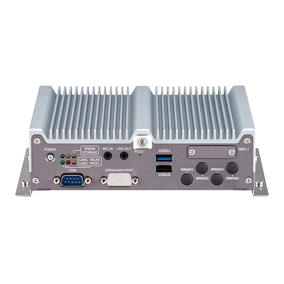
Nexcom VTC 1031 Series User Manual (123 pages)
Vehicle Telematics & Railway Computer
Brand:
Nexcom
| Category:
Desktop
| Size: 13 MB
Table of Contents
Table of Contents
2
Acknowledgements
5
Copyright
5
Declaration of Conformity
5
Disclaimer
5
Preface
5
Regulatory Compliance Statements
5
Rohs Compliance
6
Warranty and RMA
7
Installation Recommendations
9
Safety Information
9
Safety Precautions
10
Conventions Used in this Manual
11
Technical Support and Assistance
11
Global Service Contact Information
12
Package Contents
14
Ordering Information
16
Chapter 1: Product Introduction
17
Physical Features
17
VTC 1031 Front View
17
VTC 1031 Rear View
17
Physical Features
18
VTC 1031-C2 Front View
18
VTC 1031-C2 Rear View
18
Physical Features
19
Nrok 1031 Front View
19
Nrok 1031 Rear View
19
Physical Features
20
Nrok 1031-C2 Front View
20
Nrok 1031-C2 Rear View
20
VTC 1031 Series Overview
21
VTC 1031 Key Features
21
Nrok 1031 Series Overview
22
Nrok 1031 Key Features
22
Hardware Specifications
23
Mechanical Dimensions
28
Vtc 1031
28
Vtc 1031-C2
29
Nrok 1031
30
Nrok 1031-C2
31
Chapter 2: External Connectors Pinout Description
32
Connector Numbering
32
Power Button
36
LED Indicators
36
MIC-In Connector
37
Line-Out Connector
37
Reset Switch
38
USB 3.2 Gen 2
38
Usb 2.0
39
SIM1 Micro-SIM Socket
39
DB9 (COM) for Full RS232/RS422/RS485
40
DB9 Expansion Port (Optional)
40
LED for Poe1/Poe2
41
Poe LAN1 Port
42
Poe LAN2 Port
42
Audio
43
Poe M12 X-Coded 8-Pin LAN1 Connector
43
Poe M12 X-Coded 8-Pin LAN2 Connector
44
DC Input (VTC 1031 and VTC 1031-C2 Only)
44
RJ45 LAN1 Port
45
RJ45 LAN2 Port
45
Screw Hole for HDMI Wire Mount
46
Hdmi
47
Multi Port
47
Vga
48
DC Input (Nrok 1031 and Nrok 1031-C2 Only)
49
M12 X-Coded 8-Pin LAN1 Connector
49
M12 X-Coded 8-Pin LAN2 Connector
50
M12 A-Coded 8-Pin USB 2.0 Connector
50
Chapter 3: Jumpers and Connectors
51
Before You Begin
51
Precautions
51
Jumper Settings
52
Locations of the Internal Jumpers and Connectors
53
Top View
53
Bottom View
54
Storage Expansion Board
55
Jumpers
56
RTC Clear CMOS Selection Switch
56
RS485 Terminator Resistor Selection Switch
56
PIO PULL-HIGH Selection Switch
57
RTC Switch
57
CAN Terminator Resistor Selection Switch
58
Connector Pin Definitions
59
Poe Board to Board Connector
59
3042/3050/3052 Key B Socket
60
Full Size Mini-Pcie Socket (USB 2.0, Pcie 3.0)
61
3042 Key B Socket
62
2230 Key E Socket (USB 2.0, Pcie 3.0X2)
63
Audio Connector
64
Micro-Sim1/Micro-SIM2 SIM Slot
64
SATA Board to Board Connector
65
ESPI Debug Port Connector
66
USB2.0 Connector (Nrok 1031 and Nrok 1031-C2)
66
RTC Battery Connector
67
USB2.0 Connector
67
COM Connector (RS232/422/485)
68
DR Connector
68
GNSS Connector
69
MCU Debug Port Connector
69
MCU Download Pin Header
70
Storage Board Connector
71
M.2 Key M 2280 Connector
71
SATA Connector
72
Chapter 4: System Setup
73
Removing the Chassis for Storage Devices Installation
73
Installing a SATA Hard Drive
75
Installing an M.2 Storage Device
76
Removing the Poe Board
77
Installing an Internal SIM Card
79
Installing a WWAN Module (M.2)
80
Removing the Storage Board
82
Installing a SO-DIMM Memory Module
84
Installing a WLAN Module
85
Installing a Msata Module
87
Installing a SIM Card
88
Appendix A: Software Demo Utility for I/O Ports of Function Control
89
Menu Screen
89
System 1
89
System 2
91
I/O
92
Module
94
Event
96
G-Sensor
97
CAN Bus
99
Appendix B: GNSS Feature
101
U-Blox NEO-M9N Overview
101
Technical Specifications
101
U-Blox NEO-M9L Overview
104
Technical Specifications
105
Appendix D: Signal Connection of DI/DO
107
Multi Port Pinout Description
107
Digital Input
108
Digital Output
109
Appendix E: Pin Definition for the Multiport Cable
110
P1 Connector Pinout
111
P2 Connector Pinouts
111
P3 Connector Pinouts
112
P4 Connector Pinouts
112
P5 Connector Pinouts
113
P6 Connector Pinouts
113
P7 Connector Pinouts
114
P1 Connector Pinout
116
P2 and P3 Connector Pinouts
116
CN1 Connector Pinout
118
CN2 and CN3 Connector Pinouts
118
Appendix F: Vehicle Power Management Setup
119
Power-On Delay Setting
119
Power-Off Delay Setting
120
Appendix G: Power Consumption
122
Advertisement
Advertisement
Related Products
Nexcom VTC 6100
Nexcom VTC 1911
Nexcom VTC 7260
Nexcom VTC 6222
Nexcom VTC 7252 Series
Nexcom VTC 1011 Series
Nexcom VTC 1011-C2K
Nexcom VTC 1010
Nexcom VTC 1020 Series
Nexcom VTC 1020-PA
Nexcom Categories
Motherboard
Desktop
Industrial PC
Network Hardware
Digital Signage
More Nexcom Manuals
Login
Sign In
OR
Sign in with Facebook
Sign in with Google
Upload manual
Upload from disk
Upload from URL