
Related Manuals for Nexcom NISE 105/105A


Summary of Contents for Nexcom NISE 105/105A
-
Page 1: User Manual
NEXCOM International Co., Ltd. Industrial Computing Solutions Fan-less Computer NISE 105/105A User Manual NEXCOM International Co., Ltd. www.nexcom.com Published July 2014... -
Page 2: Table Of Contents
Knowing Your NISE 105 ................4 Internal Connectors ................17 Front Panel ..................4 BIOS Pin Header ................17 Rear Panel ...................5 RTC Switch ..................17 Mechanical Dimensions ................6 Mic-in Pin Header ................18 Copyright © 2013 NEXCOM International Co., Ltd. All Rights Reserved. NISE 105/105A User Manual... - Page 3 Removing the Chassis Cover ..............31 Installing a SO-DIMM ................33 Installing a Wireless LAN Module (half-size) ...........34 Installing a Wireless LAN Module (full-size) ..........36 Installing a SIM Card ................38 Copyright © 2013 NEXCOM International Co., Ltd. All Rights Reserved. NISE 105/105A User Manual...
-
Page 4: Preface
No describes how to keep the system CE compliant. part of this manual may be reproduced, copied, translated or transmitted in any form or by any means without the prior written consent from NEXCOM Declaration of Conformity International Co., Ltd. -
Page 5: Rohs Compliance
(Cr6+) < 0.1% or 1,000ppm, Polybrominated biphenyls (PBB) < 0.1% or 1,000ppm, and Polybrominated diphenyl Ethers (PBDE) < 0.1% or 1,000ppm. In order to meet the RoHS compliant directives, NEXCOM has established an engineering and manufacturing task force to implement the introduction of green products. -
Page 6: Warranty And Rma
(manuals, cable, etc.) and any components from the card, such as CPU and RAM. If the components were suspected as part of the problems, ▪ If RMA goods can not be repaired, NEXCOM will return it to the customer please note clearly which components are included. Otherwise, NEXCOM without any charge. - Page 7 ESD workstation. If no such station is available, you can provide some ESD protection by wearing an antistatic wrist strap and attaching it to a metal part of the computer chassis. Copyright © 2013 NEXCOM International Co., Ltd. All Rights Reserved. NISE 105/105A User Manual...
-
Page 8: Safety Information
Code, ANSI/NFPA 70 and Canadian Electrical Code, Part I, CSA C22.1. can damage the soft metal or plastic parts of the connectors. viii Copyright © 2013 NEXCOM International Co., Ltd. All Rights Reserved. NISE 105/105A User Manual... -
Page 9: Safety Precautions
RECOMMENDED BY THE MANUFACTURER. DISCARD USED BATTERIES ACCORDING TO THE MANUFACTURER’S INSTRUCTIONS. 10. All cautions and warnings on the equipment should be noted. Copyright © 2013 NEXCOM International Co., Ltd. All Rights Reserved. NISE 105/105A User Manual... -
Page 10: Technical Support And Assistance
Preface Technical Support and Assistance Conventions Used in this Manual 1. For the most updated information of NEXCOM products, visit NEXCOM’s Warning: website at www.nexcom.com. Information about certain situations, which if not observed, can cause personal injury. This will prevent injury to yourself 2. -
Page 11: Global Service Contact Information
13F, No.920, Chung-Cheng Rd., ZhongHe District, Beijing, 100094, China New Taipei City, 23586, Taiwan, R.O.C. Tel: +86-010-5704-2680 Tel: +886-2-8226-7796 Fax: +86-010-5704-2681 Fax: +886-2-8226-7792 Email: sales@nexcom.cn Email: sales@nexcom.com.tw www.nexcom.cn www.nexcom.com.tw Copyright © 2013 NEXCOM International Co., Ltd. All Rights Reserved. NISE 105/105A User Manual... -
Page 12: United Kingdom
Fax: +86-755-8332-7213 Via Gaudenzio Ferrari 29, Email: sales@nexcom.cn 21047 Saronno (VA), Italia www.nexcom.cn Tel: +39 02 9628 0333 Fax: +39 02 9286 9215 Email: nexcomitalia@nexcom.eu www.nexcomitalia.it Copyright © 2013 NEXCOM International Co., Ltd. All Rights Reserved. NISE 105/105A User Manual... -
Page 13: Ordering Information
Intel Atom™ Processor E3826 Dual Core Fanless System ® NISE 105A (P/N: 10J00010500X0) Intel ® Atom™ Processor E3826 Dual Core All in one Fanless System xiii Copyright © 2013 NEXCOM International Co., Ltd. All Rights Reserved. NISE 105/105A User Manual... -
Page 14: Chapter 1: Product Introduction
I120IT LAN ports support WoL, Teaming and PXE ® ▪ Support 9-30VDC input ▪ 2x USB2.0 & 1 x USB3.0 ▪ 4x COM ports (COM1 & COM2 with RS232/422/485, jumper-free setting) Copyright © 2013 NEXCOM International Co., Ltd. All Rights Reserved. NISE 105/105A User Manual... -
Page 15: Hardware Specifications
(COM2 Only) ▪ Windows 8 ▪ 1x Remote Power ON/OFF Switch ▪ Windows Embedded Standard 8 ▪ 1x 2-pin DC input, support +9 to 30VDC input Copyright © 2013 NEXCOM International Co., Ltd. All Rights Reserved. NISE 105/105A User Manual... - Page 16 ▪ Vibration Protection w/CFast & SSD Condition: – Random: 2Grms @ 5~500 Hz, IEC60068-2-64 – Sinusoidal: 2Grms @ 5~500 Hz, IEC60068-2-6 Certifications ▪ CE ▪ FCC Class A ▪ UL/cUL Copyright © 2013 NEXCOM International Co., Ltd. All Rights Reserved. NISE 105/105A User Manual...
-
Page 17: Knowing Your Nise 105
Indicates the power status and HDD activity of the system. GPIO/Battery LEDs Indicates the status of the battery and GPIO. Power Button Press to power-on or power-off the system. Copyright © 2013 NEXCOM International Co., Ltd. All Rights Reserved. NISE 105/105A User Manual... -
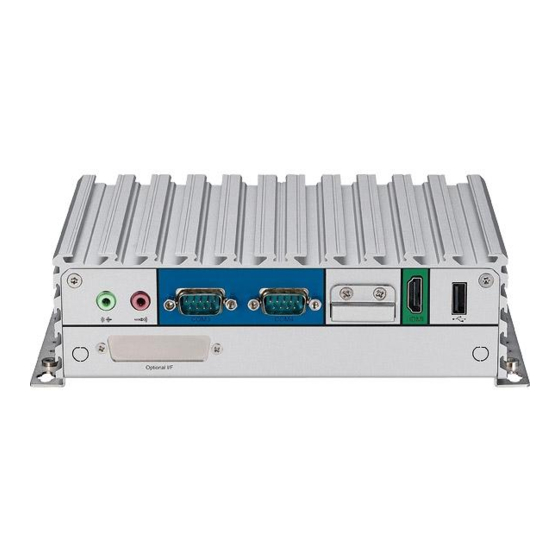
Page 18: Rear Panel
Used to connect a high-definition display. USB 2.0 Fieldbus USB 2.0 port to connect the system with USB 2.0/1.1 devices. Fieldbus Expansion slot for add-on fieldbus modules. Copyright © 2013 NEXCOM International Co., Ltd. All Rights Reserved. NISE 105/105A User Manual... -
Page 19: Mechanical Dimensions
Chapter 1: Product Introduction Mechanical Dimensions Copyright © 2013 NEXCOM International Co., Ltd. All Rights Reserved. NISE 105/105A User Manual... -
Page 20: Chapter 2: Jumpers And Connectors
Static electricity can damage many of the electronic ▪ Use correct screws and do not over tighten screws. components. Humid environments tend to have less static electricity than Copyright © 2013 NEXCOM International Co., Ltd. All Rights Reserved. NISE 105/105A User Manual... -
Page 21: Jumper Settings
(on) and open (off). Two-Pin Jumpers: Open (Left) and Short (Right) Three-Pin Jumpers: Pins 1 and 2 are Short Copyright © 2013 NEXCOM International Co., Ltd. All Rights Reserved. NISE 105/105A User Manual... -
Page 22: Nise 105 System Components
COM4 COM3 BATTERY MIC IN LINE OUT HDMI USB2.0 BAT1 JP16 BAT1 JP13 JFW1 JP10 JP12 JP11 LAN1 JP10 CN10 CFAST USB2.0 DVI-I LAN1 LAN2 USB3.0 Copyright © 2013 NEXCOM International Co., Ltd. All Rights Reserved. NISE 105/105A User Manual... -
Page 23: Jumpers
Chapter 2: Jumpers and Connectors Jumpers AT/ATX Pin Header Connector type: 1x3 3-pin header, 2.0mm pitch Connector location: JP5 Function 2-3* Copyright © 2013 NEXCOM International Co., Ltd. All Rights Reserved. NISE 105/105A User Manual... -
Page 24: Connector Pin Definitions
DDC_DATA VSYNC_VGA USB3_TX0_P_C P5V_OC01_C TX1- TX1+ USB_1N_C USB_1P_C F_GND DVI_VCC(+5V) F_GND F_GND HotPlugDet F_GND TX0- TX0+ DDCCLK_VGA DDCDATA_VGA TXCLK+ TXCLK- GREEN BLUE HSYNC_VGA VGADET CHASSIS_GND CHASSIS_GND Copyright © 2013 NEXCOM International Co., Ltd. All Rights Reserved. NISE 105/105A User Manual... -
Page 25: Lan1 And Lan2 Ports
LAN2_MDI0P LAN2_MDI0N LAN1_MDI1P LAN1_MDI1N LAN2_MDI1P LAN2_MDI1N LAN1_MDI2P LAN1_MDI2N LAN2_MDI2P LAN2_MDI2N LAN1_MDI3P LAN1_MDI3N LAN2_MDI3P LAN2_MDI3N V1P5_LAN V1P5_LAN2 LAN1_LINK100# LAN1_LINK1G# LAN2_LINK100# LAN2_LINK1G# LAN1_LED_ACT# 3VSB LAN2_LED_ACT# 3VSB CHASSIS_GND CHASSIS_GND Copyright © 2013 NEXCOM International Co., Ltd. All Rights Reserved. NISE 105/105A User Manual... -
Page 26: Cfast
S7 PC1 PC17 3VSB Definition Definition PWRLED_N PWRLED_P SATA_TXP1 SATA_TXN1 SATA_RXN1 SATA_RXP1 CFAST_CDI CFAST_ACCESS PC10 PC11 PC12 PC13 VCC3 PC14 VCC3 PC15 PC16 PC17 CFAST_CDO CHASSIS_GND CHASSIS_GND Copyright © 2013 NEXCOM International Co., Ltd. All Rights Reserved. NISE 105/105A User Manual... -
Page 27: External I/O Interfaces - Rear Panel
Definition SP3_DCD SP3_DATA- SP3_TX- OUT_L SP3_RXD SP3_DATA+ SP3_TX+ SP3_TXD SP3_RX+ Mic-in SP3_DTR SP3_RX- Definition Definition MIC_GND MIC1_R3 SP3_DSR SP3_RTS- SP3_RTS SP3_RTS+ MIC1_L3 SP3_CTS SP3_CTS+ SP3_RI SP3_CTS- Copyright © 2013 NEXCOM International Co., Ltd. All Rights Reserved. NISE 105/105A User Manual... -
Page 28: Com4 Port
SP4_DATA+ SP4_TX+ HDMI_DATA0_P SP4_TXD SP4_RX+ HDMI_DATA0_N HDMI_CLK_P SP4_DTR SP4_RX- HDMI_CLK_N SP4_DSR SP4_RTS- HDMI_CTRL_CLK HDMI_CTRL_DATA SP4_RTS SP4_RTS+ VCC5_HDMI SP4_CTS SP4_CTS+ HDMI_HPD_R CHASSIS_GND SP4_RI SP4_CTS- CHASSIS_GND CHASSIS_GND CHASSIS_GND Copyright © 2013 NEXCOM International Co., Ltd. All Rights Reserved. NISE 105/105A User Manual... -
Page 29: Usb 2.0 Port
Chapter 2: Jumpers and Connectors USB 2.0 Port Connector type: DB-9 port, 9-pin D-Sub Connector location: CN5 Definition Definition P5V_OC2_C USB_2N_C USB_2P_C CHASSIS_GND CHASSIS_GND CHASSIS_GND Copyright © 2013 NEXCOM International Co., Ltd. All Rights Reserved. NISE 105/105A User Manual... -
Page 30: Internal Connectors
Internal Connectors BIOS Pin Header RTC Switch Connector type: 2x3 6-pin header, 2.0mm Connector location: SW1 Connector location: JFW1 Definition Definition Definition CS#0 3VSB RTC_TEST# SRTC_TEST# Copyright © 2013 NEXCOM International Co., Ltd. All Rights Reserved. NISE 105/105A User Manual... -
Page 31: Mic-In Pin Header
Connector type: 1x4 4-pin header, 2.0mm pitch Connector type: 1x4 4-pin header, 2.0mm pitch Connector location: JP2 Connector location: JP1 Definition Definition MIC1_L3 OUT_L MIC_GND AGND MIC1_R3 OUT_R Copyright © 2013 NEXCOM International Co., Ltd. All Rights Reserved. NISE 105/105A User Manual... -
Page 32: Line-In Pin Header
Connector type: 2x4 8-pin header, 2.54mm pitch Connector location: JP6 Connector location: JP8 Definition Definition Definition FLIN_L VCC5 VCC5 LIN_JD KDAT_R MDAT_R LIN_GND KCLK_R MCLK_R FLIN_R Copyright © 2013 NEXCOM International Co., Ltd. All Rights Reserved. NISE 105/105A User Manual... -
Page 33: Fan Connector
Connector type: 2x5 10-pin header, 2.00mm pitch Connector location: CN7 Connector location: JP13 Definition Definition Definition VCC5 VCC12 ICH_GPO0_OUT ICH_GPI0_IN CPUFANIN ICH_GPO1_OUT ICH_GPI1_IN CPUFANOUT ICH_GPO2_OUT ICH_GPI2_IN ICH_GPO3_OUT ICH_GPI3_IN Copyright © 2013 NEXCOM International Co., Ltd. All Rights Reserved. NISE 105/105A User Manual... -
Page 34: Lan1A Led Pin Header
Connector type: 2x2 4-pin header, 2.00mm pitch Connector type: 2x2 4-pin header, 2.00mm pitch Connector location: JP11 Connector location: JP10 Definition Definition LAN1_ACT_CON LAN2_ACT_CON LAN1_LED_ACT# LAN2_LED_ACT# LAN1_LINK1G# LAN2_LINK1G# LAN1_100#_CON LAN2_100#_CON Copyright © 2013 NEXCOM International Co., Ltd. All Rights Reserved. NISE 105/105A User Manual... -
Page 35: Reset Pin Header
Connector type: 2x7 14-pin header, 2.0mm pitch Connector location: JP7 Connector location: JP9 Definition Definition Definition PWR_LED_N POWER_LED_PWR PM_RESET#_J HDD_LED_N HDD_LED_PWR SMB_CLK SMB_DATA 3VSB SLP_S3# PSON PBT_SW PM_RESET#_J Copyright © 2013 NEXCOM International Co., Ltd. All Rights Reserved. NISE 105/105A User Manual... -
Page 36: 3.5G Line-Out Pin Header
Connector type: 1x3 3-pin header, 2.54mm pitch Connector type: 1x3 3-pin header, 2.54mm pitch Connector location: JP3 Connector location: JP4 Definition Definition LOUT_RL MIC_RL LOUT_RR MIC_RR ANGND ANGND Copyright © 2013 NEXCOM International Co., Ltd. All Rights Reserved. NISE 105/105A User Manual... -
Page 37: Power Pin Header
Connector type: 1x6 JST, 6-pin header, 2.5mm pitch Connector type: 1x3 3-pin header, 2.0mm pitch Connector location: J2 Connector location: JP12 Definition Definition Definition PBT_TR 12VSB 12VSB 12VSB PBT_SW PM_RESET#_J POWER_STATUS Copyright © 2013 NEXCOM International Co., Ltd. All Rights Reserved. NISE 105/105A User Manual... -
Page 38: Flash Mcu Code Pin Header
Chapter 2: Jumpers and Connectors Flash MCU Code Pin Header Connector type: 1x4 4-pin header, 2.0mm pitch Connector location: JP16 Definition 3VSB SBW_TCK SBW_TDIO Copyright © 2013 NEXCOM International Co., Ltd. All Rights Reserved. NISE 105/105A User Manual... -
Page 39: Locations Of The Jumpers And Connectors For The I/O Daughterboard
Chapter 2: Jumpers and Connectors Locations of the Jumpers and Connectors for the I/O Daughterboard LED1 LED2 LED1 LED2 9-30V COM2 COM1 DC INPUT Copyright © 2013 NEXCOM International Co., Ltd. All Rights Reserved. NISE 105/105A User Manual... -
Page 40: Connector Pin Definitions
Definition RS232 RS485 RS422 PBT_PU Definition Definition Definition SP1_DCD SP1_DATA- SP1_TX- SP1_RXD SP1_DATA+ SP1_TX+ SP1_TXD SP1_RX+ SP1_DTR SP1_RX- SP1_DSR SP1_RTS- SP1_RTS SP1_RTS+ SP1_CTS SP1_CTS+ SP1_RI SP1_CTS- Copyright © 2013 NEXCOM International Co., Ltd. All Rights Reserved. NISE 105/105A User Manual... -
Page 41: Com2 Port
RS232 RS485 RS422 Definition GND_FLT Definition Definition Definition SP1_DCD SP1_DATA- SP1_TX- SP1_RXD SP1_DATA+ SP1_TX+ SP1_TXD SP1_RX+ SP1_DTR SP1_RX- SP1_DSR SP1_RTS- SP1_RTS SP1_RTS+ SP1_CTS SP1_CTS+ SP1_RI SP1_CTS- Copyright © 2013 NEXCOM International Co., Ltd. All Rights Reserved. NISE 105/105A User Manual... -
Page 42: Gpio/Battery Led
Chapter 2: Jumpers and Connectors GPIO/Battery LED Power/HDD LED Connector location: LED2 Connector location: LED1 Definition Definition VCC5 VCC5 BAT_LED VCC5 GPIO_LED_N PWR_LED_N HDD_LED_N Copyright © 2013 NEXCOM International Co., Ltd. All Rights Reserved. NISE 105/105A User Manual... -
Page 43: Internal Connectors
Chapter 2: Jumpers and Connectors Internal Connectors COM2 RI Pin Header Connector type: 1x5 5-pin header, 2.0mm Connector location: J1 Definition VCC5 VCC12 4-5* RING Copyright © 2013 NEXCOM International Co., Ltd. All Rights Reserved. NISE 105/105A User Manual... -
Page 44: Chapter 3: System Setup
1. Locate the 6 screws on the bottom side of the chassis cover. 2. Remove the 6 screws on the bottom side of the chassis cover. Copyright © 2013 NEXCOM International Co., Ltd. All Rights Reserved. NISE 105/105A User Manual... - Page 45 Chapter 3: System Setup 3. Remove the chassis cover. Copyright © 2013 NEXCOM International Co., Ltd. All Rights Reserved. NISE 105/105A User Manual...
-
Page 46: Installing A So-Dimm
The ejector tabs at the ends of the socket will automatically snap into the locked position to hold the module in place. SO-DIMM 2. Locate the SO-DIMM socket. Copyright © 2013 NEXCOM International Co., Ltd. All Rights Reserved. NISE 105/105A User Manual... -
Page 47: Installing A Wireless Lan Module (Half-Size)
1. Locate the mini-PCIe slot on the board. 3. Install the mini-PCIe bracket to the mini-PCIe module. Screw Mini-PCIe slot Mini-PCIe bracket 2. Remove the mini-PCIe bracket from the board. Copyright © 2013 NEXCOM International Co., Ltd. All Rights Reserved. NISE 105/105A User Manual... - Page 48 5. Push the module down and secure it with the screws. until the gold-plated connector on the edge of the module completely disappears into the slot. Copyright © 2013 NEXCOM International Co., Ltd. All Rights Reserved. NISE 105/105A User Manual...
-
Page 49: Installing A Wireless Lan Module (Full-Size)
Mini-PCIe slot Mini-PCIe bracket 2. Remove the mini-PCIe bracket from the board. Copyright © 2013 NEXCOM International Co., Ltd. All Rights Reserved. NISE 105/105A User Manual... - Page 50 Chapter 3: System Setup 4. Push the module down and secure it with the screws. Copyright © 2013 NEXCOM International Co., Ltd. All Rights Reserved. NISE 105/105A User Manual...
-
Page 51: Installing A Sim Card
1. Locate the SIM card holder and release the cover. 3. Close the cover and secure the holder to the original position. SIM card holder 2. Place the SIM card onto the holder. Copyright © 2013 NEXCOM International Co., Ltd. All Rights Reserved. NISE 105/105A User Manual... -
Page 52: Installing A Sata Hard Drive
3. Place the 2.5" HDD into the internal HDD bracket then use the screws to 2. Locate the internal HDD bracket and remove all the 3 screws on the HDD secure the 2.5" HDD in place. bracket. Copyright © 2013 NEXCOM International Co., Ltd. All Rights Reserved. NISE 105/105A User Manual... - Page 53 Chapter 3: System Setup 4. Place the internal HDD bracket into its original position. 5. Secure the internal HDD bracket by screwing the screws in a clockwise direction. Copyright © 2013 NEXCOM International Co., Ltd. All Rights Reserved. NISE 105/105A User Manual...
-
Page 54: Installing A Cfast Card
1. Locate the CFast slot at the front and remove the cover on the slot. 2. Insert the CFast card into the slot and fasten the cover. Copyright © 2013 NEXCOM International Co., Ltd. All Rights Reserved. NISE 105/105A User Manual... -
Page 55: Installing A Battery
1. Locate the battery slot at the front and remove the cover on the slot. 2. Insert the battery into the slot and fasten the cover. Copyright © 2013 NEXCOM International Co., Ltd. All Rights Reserved. NISE 105/105A User Manual... -
Page 56: Packing
Chapter 3: System Setup Packing NISE 105 plastic bag and EPE reference. Front View of Packing Rear View of Packing Copyright © 2013 NEXCOM International Co., Ltd. All Rights Reserved. NISE 105/105A User Manual... - Page 57 Chapter 3: System Setup Top View of Packing Bottom View of Packing Copyright © 2013 NEXCOM International Co., Ltd. All Rights Reserved. NISE 105/105A User Manual...
-
Page 58: Chapter 4: Bios Setup
It is important, therefore, first to try to understand all the setup options, and the BIOS is updated in the future. second, to make settings appropriate for the way you use the computer. To check for the latest updates and revisions, visit the NEXCOM Web site at When to Configure the BIOS www.nexcom.com.tw. -
Page 59: Default Configuration
Ctrl Saves and exits the Setup program. TO ENTER SETUP BEFORE BOOT PRESS Press <Enter> to enter the highlighted sub-menu Press the key to enter Setup: Copyright © 2013 NEXCOM International Co., Ltd. All Rights Reserved. NISE 105/105A User Manual... - Page 60 When “” appears on the left of a particular field, it indicates that a submenu which contains additional options are available for that field. To display the submenu, move the highlight to that field and press Copyright © 2013 NEXCOM International Co., Ltd. All Rights Reserved. NISE 105/105A User Manual...
-
Page 61: Bios Setup Utility
System Date [Fri 03/14/2014] F2: Previous Values System Time [18:01:51] F3: Optimized Defaults F4: Save & Exit ESC: Exit Version 2.16.1242. Copyright (C) 2013 American Megatrends, Inc. Copyright © 2013 NEXCOM International Co., Ltd. All Rights Reserved. NISE 105/105A User Manual... -
Page 62: Advanced
Select the highest ACPI sleep state the system will enter when the suspend Version 2.16.1242. Copyright (C) 2013 American Megatrends, Inc. button is pressed. The options are Suspend Disabled and S3 (Suspend to RAM). Copyright © 2013 NEXCOM International Co., Ltd. All Rights Reserved. NISE 105/105A User Manual... -
Page 63: Serial Port 1 Configuration
Displays the Super I/O chip used on the board. Onboard Serial Port Mode Select this to change the serial port mode to RS232, RS422, RS485 or RS485 Auto. Copyright © 2013 NEXCOM International Co., Ltd. All Rights Reserved. NISE 105/105A User Manual... -
Page 64: Serial Port 2 Configuration
Select this to change the serial port mode to RS232, RS422, RS485 or RS485 Select this to change the serial port mode to RS232, RS422, RS485 or RS485 Auto. Auto. Copyright © 2013 NEXCOM International Co., Ltd. All Rights Reserved. NISE 105/105A User Manual... -
Page 65: Ppm Configuration
EIST Enables or disables Intel ® SpeedStep. Onboard Serial Port Mode Select this to change the serial port mode to RS232, RS422, RS485 or RS485 Auto. Copyright © 2013 NEXCOM International Co., Ltd. All Rights Reserved. NISE 105/105A User Manual... - Page 66 CPU Temperature Detects and displays the current CPU temperature. System Temperature Detects and displays the current system temperature. Fan Speed Detects and displays the fan speed. Copyright © 2013 NEXCOM International Co., Ltd. All Rights Reserved. NISE 105/105A User Manual...
-
Page 67: Cpu Configuration
Windows, this problem may occur. To avoid this problem, enable Version 2.16.1242. Copyright (C) 2013 American Megatrends, Inc. this field to limit the return value to 3 or lesser than 3. Copyright © 2013 NEXCOM International Co., Ltd. All Rights Reserved. NISE 105/105A User Manual... -
Page 68: Ide Configuration
Enables or disables SATA device. SATA Speed Support Configures the SATA controller to Gen1 or Gen2 speed. SATA Mode Configures the SATA as IDE, AHCI or RAID mode. Copyright © 2013 NEXCOM International Co., Ltd. All Rights Reserved. NISE 105/105A User Manual... -
Page 69: Chipset
This is a workaround for OSs that does not support XHCI hand-off and EHCI Hand-off. The XHCI and EHCI ownership change should be claimed by the XHCI and EHCI driver respectively. Copyright © 2013 NEXCOM International Co., Ltd. All Rights Reserved. NISE 105/105A User Manual... - Page 70 F3: Optimized Defaults F4: Save & Exit ESC: Exit Version 2.16.1242. Copyright (C) 2013 American Megatrends, Inc. High Precision Timer Enables or disables the high precision event timer. Copyright © 2013 NEXCOM International Co., Ltd. All Rights Reserved. NISE 105/105A User Manual...
-
Page 71: Usb Configuration
Enables or disables PCH USB rate matching hubs mode. Azalia HDMI Codec USB EHCI Debug Enables or disables internal HDMI codec for Azalia. Enables or disables PCH EHCI debug capability. Copyright © 2013 NEXCOM International Co., Ltd. All Rights Reserved. NISE 105/105A User Manual... -
Page 72: Pci Express Configuration
Version 2.16.1242. Copyright (C) 2013 American Megatrends, Inc. PCI Express Port 0 to PCI Express Port 2 Enables or disables the PCI Express ports 0 to 2 on the chipset. Copyright © 2013 NEXCOM International Co., Ltd. All Rights Reserved. NISE 105/105A User Manual... -
Page 73: Security
Fast Boot When enabled, the BIOS will shorten or skip some check items during POST. This will decrease the time needed to boot the system. Copyright © 2013 NEXCOM International Co., Ltd. All Rights Reserved. NISE 105/105A User Manual... -
Page 74: Save & Exit
To restore the BIOS to default settings, select this field then press <Enter>. A dialog box will appear. Confirm by selecting Yes. Version 2.16.1242. Copyright (C) 2013 American Megatrends, Inc. Sets the system boot order. Copyright © 2013 NEXCOM International Co., Ltd. All Rights Reserved. NISE 105/105A User Manual... -
Page 75: Appendix A: Power Consumption
3. Measure the power consumption and record it. 4. Run Burn-in test program to apply 100% full loading 5. Measure the power consumption and record it. Copyright © 2013 NEXCOM International Co., Ltd. All Rights Reserved. NISE 105/105A User Manual... -
Page 76: Appendix B: Gpi/O Programming Guide
High A00h (Bit1) Control the GPO 0/1/2/3 level from I/O port A03h bit6/ A02h bit5/ A07h bit0/ A07h bit1. The bit is Set/Clear indicated output High/Low Copyright © 2013 NEXCOM International Co., Ltd. All Rights Reserved. NISE 105/105A User Manual... - Page 77 #define GPO1_LO outportb(0xA02, 0x00) #define GPO2_HI outportb(0xA07, GPO2) #define GPO2_LO outportb(0xA07, 0x00) #define GPO3_HI outportb(0xA07, GPO3) #define GPO3_LO outportb(0xA07, 0x00) void main(void) GPO0_HI; GPO1_LO; GPO2_HI; GPO3_LO; Copyright © 2013 NEXCOM International Co., Ltd. All Rights Reserved. NISE 105/105A User Manual...
-
Page 78: Appendix C: Watchdog Timer Setting
WDT_SET); outportb(SUPERIO_PORT+1, 0x90); # Use the second # Use the minute, change value to 0x10 # Set WDT sec/min outportb(SUPERIO_PORT, WDT_VALUE); outportb(SUPERIO_PORT+1, 0x05); #Set 5 seconds Copyright © 2013 NEXCOM International Co., Ltd. All Rights Reserved. NISE 105/105A User Manual...
Need help?
Do you have a question about the NISE 105/105A and is the answer not in the manual?
Questions and answers