
Related Manuals for Nexcom nROK 7251 Series


Summary of Contents for Nexcom nROK 7251 Series
- Page 1 NEXCOM International Co., Ltd. Mobile Computing Solutions Railway Computer nROK 7251 Series User Manual NEXCOM International Co., Ltd. www.nexcom.com Published March 2021...
-
Page 2: Table Of Contents
COM3 RS232/RS422/RS485 Connector ..........17 nROK 7251 Series Hardware Specifications ..........4 DC Input (nROK 7251-WI-7C4IP) ............18 Connector Numbering ................7 DC Input (nROK 7251-7C4 and nROK 7251-7A) ........18 Copyright © 2020 NEXCOM International Co., Ltd. All Rights Reserved. nROK 7251 Series User Manual... - Page 3 LTE Module with 2 x External SIM ..........35 Jumper Settings ..................20 (BOM Optional) nROK 7251 Series Connector Specification & Jumper Setting ....21 M.2 3042 Key B Socket (USB 2.0, USB 3.1 Gen2) Locations of the Jumpers and Connectors for the Carrier Board ..21 for LTE/5G NR Module with 2 x External SIM .........36...
- Page 4 P2 Connector Pinout ................80 GPIO Connector ................80 P2 Connector Pinout ................82 P1 and P3 Connector Pinouts ..............82 Green (Line-out) Connector ...............82 Pink (Mic-in) Connector ..............83 Copyright © 2020 NEXCOM International Co., Ltd. All Rights Reserved. nROK 7251 Series User Manual...
-
Page 5: Preface
The information in this document is subject to change without prior notice designed to provide reasonable protection against harmful interference when and does not represent commitment from NEXCOM International Co., Ltd. the equipment is operated in a commercial environment. This equipment... -
Page 6: Rohs Compliance
0.1% or 1,000ppm, and Polybrominated diphenyl Ethers (PBDE) < 0.1% or 1,000ppm. In order to meet the RoHS compliant directives, NEXCOM has established an engineering and manufacturing task force in to implement the introduction of green products. The task force will ensure that we follow the standard... -
Page 7: Warranty And Rma
▪ Replace with 3rd party products if needed. encountered and note anything abnormal or, print out any on-screen ▪ If RMA goods can not be repaired, NEXCOM will return it to the customer messages, and describe the problems on the “NEXCOM RMA Service without any charge. - Page 8 Always power off the system before inserting or removing the SIM only with the same or equivalent type recommended by the manufacturer. card. Discard used batteries according to the manufacturer’s instructions. viii Copyright © 2020 NEXCOM International Co., Ltd. All Rights Reserved. nROK 7251 Series User Manual...
- Page 9 ACCORDING TO THE MANUFACTURER’S INSTRUCTIONS. rating marked on the product. ▪ All cautions and warnings on the equipment should be noted. Copyright © 2020 NEXCOM International Co., Ltd. All Rights Reserved. nROK 7251 Series User Manual...
-
Page 10: Technical Support And Assistance
Preface Technical Support and Assistance Conventions Used in this Manual 1. For the most updated information of NEXCOM products, visit NEXCOM’s Warning: website at www.nexcom.com. Information about certain situations, which if not observed, can cause personal injury. This will prevent injury to yourself 2. -
Page 11: Global Service Contact Information
Shanghai, 201108, China Taichung City, 406, Taiwan, R.O.C. Email: sales@nexcom.com.tw Tel: +86-21-5278-5868 Tel: +886-4-2249-1179 www.nexcom.com.tw Fax: +86-21-3251-6358 Fax: +886-4-2249-1172 Email: sales@nexaiot.com Email: sales@nexcom.cn www.nexaiot.com www.nexcom.cn Copyright © 2020 NEXCOM International Co., Ltd. All Rights Reserved. nROK 7251 Series User Manual... - Page 12 Fax: +86-23-4966-5855 Milton Keynes, Buckinghamshire Tel: +81-3-5419-7830 Email: sales@nexgol.com.cn MK8 0AB, United Kingdom Fax: +81-3-5419-7832 www.nexcobot.com/NexGOL Tel: +44-1908-267121 Email: sales@nexcom-jp.com Fax: +44-1908-262042 www.nexcom-jp.com Email: sales.uk@nexcom.eu www.nexcom.co.uk Copyright © 2020 NEXCOM International Co., Ltd. All Rights Reserved. nROK 7251 Series User Manual...
-
Page 13: Package Contents
7251 Series DVD Driver VER:1.0 603ANT0115X00 GPS/GLONASS Antenna SANAV:SM-76G SMA Male L=5000mm Waterproof M12 A Coded 5-pin (Female) to Open 603POW0378X00 Power Cable ST:MD-5108077 L=300mm xiii Copyright © 2020 NEXCOM International Co., Ltd. All Rights Reserved. nROK 7251 Series User Manual... - Page 14 602DCD1662X00 nROK 7251 Series DVD Driver VER:1.0 603ANT0115X00 GPS/GLONASS Antenna SANAV:SM-76G SMA Male L=5000mm 603POW0407X00 Power Cable ST:ST-2005011 Waterproof M23 5-pin (Female) to Open L=300mm Copyright © 2020 NEXCOM International Co., Ltd. All Rights Reserved. nROK 7251 Series User Manual...
-
Page 15: Ordering Information
Preface Ordering Information The following provides ordering information for the nROK 7251 series. ▪ nROK 7251-WI-7C4IP (P/N: 10A00725100X0) 9th generation Intel Core™ i7-9700TE, 2 x 4 GB industrial grade ® memory, DC input 24V~110V w/ isolation, 1 x VGA, 1 x LAN, 4 x PoE 802.3af/at (total 60W), IP65... -
Page 16: Chapter 1: Product Introduction
PoE1 to PoE4 Power 6 SIM Slots Indicators with Cover Antenna SSD/HDD Antenna SSD/HDD Antenna USB 2.0 COM1 COM2 COM3 Power Connector Connectors Connectors Input Button Copyright © 2020 NEXCOM International Co., Ltd. All Rights Reserved. nROK 7251 Series User Manual... -
Page 17: Nrok 7251-7A Physical Features
LAN1 LAN2 Power 6 SIM Slots Indicators with Cover Antenna SSD/HDD Antenna SSD/HDD Antenna USB 2.0 COM1 COM2 COM3 Power Connector Connectors Connectors Input Button Copyright © 2020 NEXCOM International Co., Ltd. All Rights Reserved. nROK 7251 Series User Manual... -
Page 18: Nrok 7251-Wi-7C4Ip Physical Features
USB 3.1 Audio USB 2.0 PoE1 to PoE4 Power 6 SIM Slots Button Indicators with Cover SSD/HDD Antenna SSD/HDD Antenna COM1 COM2 COM3 Connectors Connector Input Copyright © 2020 NEXCOM International Co., Ltd. All Rights Reserved. nROK 7251 Series User Manual... -
Page 19: Nrok 7251 Series Hardware Specifications
▪ 6 x Externally accessible SIM card sockets (4 x WWAN + 8 x SIM, BOM 3042 Key B socket (USB 2.0, USB 3.1 Gen2) for LTE/5G NR module with 2 x optional) w/ cover external SIM Copyright © 2020 NEXCOM International Co., Ltd. All Rights Reserved. nROK 7251 Series User Manual... - Page 20 - Operating: MIL-STD-810G, Method 514.6, Category 4, common ▪ nROK 7251-7C4, nROK 7251-7A: power input 24 VDC w/o isolation carrier US highway truck vibration exposure ▪ Reverse protection, OCP & UVP Copyright © 2020 NEXCOM International Co., Ltd. All Rights Reserved. nROK 7251 Series User Manual...
- Page 21 - Environment EN 60068-2-1, EN 60068-2-2, EN 60068-2-30 - Shock and vibration IEC 61373 Class B - Protective coating class PC1 (PC2, by request) ▪ EN 45545-2: 2013+A1:2015 Copyright © 2020 NEXCOM International Co., Ltd. All Rights Reserved. nROK 7251 Series User Manual...
-
Page 22: Connector Numbering
2 of the manual. nROK 7251-7C4 Front View nROK 7251-7C4 Rear View Copyright © 2020 NEXCOM International Co., Ltd. All Rights Reserved. nROK 7251 Series User Manual... -
Page 23: Nrok 7251-7A Front View
Chapter 1: Product Introduction nROK 7251-7A Front View nROK 7251-7A Rear View Copyright © 2020 NEXCOM International Co., Ltd. All Rights Reserved. nROK 7251 Series User Manual... -
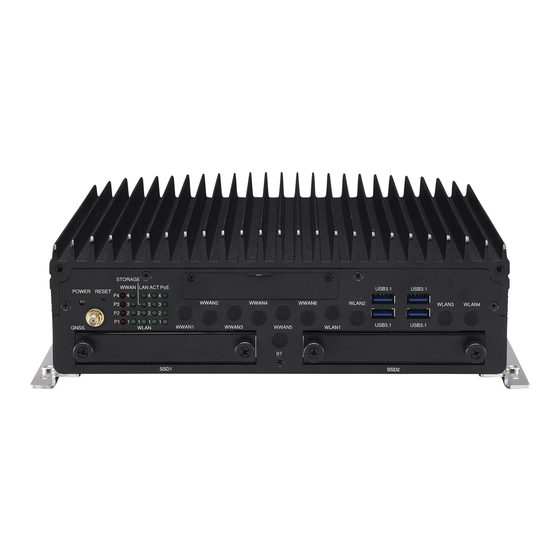
Page 24: Nrok 7251-Wi-7C4Ip Front View
Chapter 1: Product Introduction nROK 7251-WI-7C4IP Front View nROK 7251-WI-7C4IP Rear View Copyright © 2020 NEXCOM International Co., Ltd. All Rights Reserved. nROK 7251 Series User Manual... -
Page 25: Chapter 2: External Connectors Pinout Description
Reset Button Connector number: 1 Connector number: 2 Color Behavior Definition Blue On Power On Blue Off Power Off RST_BTN# Red On System power failure Copyright © 2020 NEXCOM International Co., Ltd. All Rights Reserved. nROK 7251 Series User Manual... -
Page 26: Led Indicators (Nrok 7251-7C4/7251-Wi-7C4Ip)
WLAN1 – WLAN2 Green On: WLAN active ACT1 – ACT4 Green On/Blinking: PoE LAN active/access PoE1 – PoE4 Green On: Power active on PoE port Copyright © 2020 NEXCOM International Co., Ltd. All Rights Reserved. nROK 7251 Series User Manual... -
Page 27: Sim1-1/1-2 To Sim4-1/4-2 Mini-Sim Sockets
USB 3.1 Gen 1 SIM1-1/1-2 to SIM4-1/4-2 Definition Definition Definition Definition UIM_PWR USB2.0_DATA- UIM_RST UIM_DAT USB2.0_DATA+ UIM_CLK USB3.1_RX_N USB3.1_RX_P USB3.1_TX_N USB3.1_TX_P Note: SIM4-1/4-2 (BOM optional) Copyright © 2020 NEXCOM International Co., Ltd. All Rights Reserved. nROK 7251 Series User Manual... -
Page 28: M12 Audio Connector
4 3 2 Definition Definition Definition Definition FRONT_OUT_L FRONT_OUT_JD HDMI_TX2P FRONT_OUT_R MIC_L HDMI_TX2N HDMI_TX1P MIC_JD MIC_AGND HDMI_TX1N HDMI_TX0P HDMI_TX0N HDMI_CLK_P HDMI_CLK_N HDMI_SCL HDMI_SDA HDMI_P5V HDMI_HPD Copyright © 2020 NEXCOM International Co., Ltd. All Rights Reserved. nROK 7251 Series User Manual... -
Page 29: M12 Lan1/2 Connectors (Lan2 For Nrok 7251-7A)
Connector Number: 8 Connector Number: 9 Definition Definition Definition Definition MDI0P MDI0N MDI0P MDI0N MDI1P MDI1N MDI1P MDI1N MDI2P MDI2N MDI2P MDI2N MDI3P MDI3N MDI3P MDI3N Copyright © 2020 NEXCOM International Co., Ltd. All Rights Reserved. nROK 7251 Series User Manual... -
Page 30: Vga Connector
Connector number: 10 Connector Number: 11 Definition Definition Definition Definition VGA_RED VGA_GREEN USB1_N USB1_P VGA_BLUE USB1_VCC5 USB1_GND USB2_N USB2_P USB2_VCC5 USB2_GND VGA_DATA VGA_HS VGA_VS VGA_CLK Copyright © 2020 NEXCOM International Co., Ltd. All Rights Reserved. nROK 7251 Series User Manual... -
Page 31: Dio Connector
DIO Connector COM1 RS232 Connector Connector Number: 12 Connector number: 13 Definition Definition Definition Definition GPI1 GPI2 GPI3 GPI4 GPO1 GPO2 ISO_GND GPO3 GPO4 VIN_GPIO Copyright © 2020 NEXCOM International Co., Ltd. All Rights Reserved. nROK 7251 Series User Manual... -
Page 32: Com2 Rs232 Connector
Connector number: 14 Connector number: 15 Definition Definition Definition Definition RS232 DCD#/RS422 TX- / RS232 RX/RS422_TX+ / RS485_DATA- RS485_DATA+ RS232 TX/RS422_RX+ RS232 DTR#/RS422_RX- ISO_GND DSR# RTS# CTS# Copyright © 2020 NEXCOM International Co., Ltd. All Rights Reserved. nROK 7251 Series User Manual... -
Page 33: Dc Input (Nrok 7251-Wi-7C4Ip)
(Please refer to times the power consumption of the system. (Please refer to Appendix G for system power consumption.) Appendix G for system power consumption.) Copyright © 2020 NEXCOM International Co., Ltd. All Rights Reserved. nROK 7251 Series User Manual... -
Page 34: Chapter 3: Jumpers And Switches
Chapter 3: Jumpers and Switches 3: J haPter umPers and wItChes This chapter describes how to set the jumpers on the nROK 7251 series motherboard. Before You Begin Precautions ▪ Ensure you have a stable, clean working environment. Dust and dirt can Computer components and electronic circuit boards can be damaged by get into components and cause a malfunction. -
Page 35: Jumper Settings
(on) and open (off). Two-Pin Jumpers: Open (Left) and Short (Right) Three-Pin Jumpers: Pins 1 and 2 are Short Copyright © 2020 NEXCOM International Co., Ltd. All Rights Reserved. nROK 7251 Series User Manual... -
Page 36: Nrok 7251 Series Connector Specification & Jumper Setting
Chapter 3: Jumpers and Switches nROK 7251 Series Connector Specification & Jumper Setting The figure below is the carrier board used in the nROK 7251 series. It shows the locations of the jumpers and connectors. Locations of the Jumpers and Connectors for the Carrier Board... -
Page 37: Dip Switch And Jumper Settings
Input Voltage Setup Selection Connector location: SW3 Connector location: SW4 RTC (Pin1) SRTC/ME (Pin2) POWERSW (Pin1) 12V24V (Pin2) Result Normal Normal Clear CMOS Clear ME 9~36V Copyright © 2020 NEXCOM International Co., Ltd. All Rights Reserved. nROK 7251 Series User Manual... -
Page 38: Gpio Pull Power
Chapter 3: Jumpers and Switches GPIO Pull Power Connector type: 1x3 3-pin header Connector location: JP6 Settings 2-3 On Internal ISO_5V Copyright © 2020 NEXCOM International Co., Ltd. All Rights Reserved. nROK 7251 Series User Manual... -
Page 39: Internal Connectors
Connector size: 1 x 6 = 6-pin header Connector size: 1 x 4 = 4-pin header Connector location: J12 Connector location: J13 Definition Definition Definition Definition 3.3V GPS LED ODOMETER DIRECTION 3.3V Copyright © 2020 NEXCOM International Co., Ltd. All Rights Reserved. nROK 7251 Series User Manual... -
Page 40: Gps Battery Connector
Connector size: 1 x 2 = 2-pin header Connector size: 1 x 3 = 3-pin header Connector location: J11 Connector location: J20 Definition Definition ODOMETER IN VBAT DIRECTION IN Copyright © 2020 NEXCOM International Co., Ltd. All Rights Reserved. nROK 7251 Series User Manual... -
Page 41: Rtc Battery Connector
Connector size: 1 x 10 = 10-pin header Connector location: J10 Connector location: J19 Definition Definition Definition GPIO_Vin(max 36V) VBAT GPO-4 GPO-3 GPO-2 GPO-1 GPI-4 GPI-3 GPI-2 GPI-1 Copyright © 2020 NEXCOM International Co., Ltd. All Rights Reserved. nROK 7251 Series User Manual... -
Page 42: Com1 Rs232 Db9 Connector
Connector size: 1 x 10 = 10-pin header Connector location: J4 Connector location: J3 Definition Definition Definition Definition CTS1 DSR1 CTS2 DSR2 DTR1 RXD1 DTR2 RXD2 RTS1 RTS2 TXD1 DCD1 TXD2 DCD2 Copyright © 2020 NEXCOM International Co., Ltd. All Rights Reserved. nROK 7251 Series User Manual... -
Page 43: Com3 Rs232/Rs422/Rs485 Db9 Connector
Connector size: 1 x 4 = 4-pin header Connector location: J2 Connector location: J7 and J9 Definition Definition Definition Definition USB_P CTS# DSR# USB_N POWER DTR#_RX- RX_TX+ RI#_PW RTS# TX_RX+ DCD#_TX- Copyright © 2020 NEXCOM International Co., Ltd. All Rights Reserved. nROK 7251 Series User Manual... -
Page 44: Usb Connector (For Usb M12 Connector)
Connector size: 1 x 7 = 7-pin header Connector location: J17 Connector location: CN1 and CN23 Definition Definition Definition Definition POWER USB_2N SATA_TXP0 USB_2P SATA_TXN0 POWER USB_1N SATA_RXN0 SATA_RXP0 USB_1P Copyright © 2020 NEXCOM International Co., Ltd. All Rights Reserved. nROK 7251 Series User Manual... -
Page 45: Mcu Debug Port
Connector size: 1 x 3 = 3-pin header Connector size: 2 x 4 = 8-pin header Connector location: JP2 Connector location: JP4 Definition Definition Definition 3.3V MCU_TRST MCU_TCK MCU_TDO MCU_RST MCU_TDI MCU_TMS Copyright © 2020 NEXCOM International Co., Ltd. All Rights Reserved. nROK 7251 Series User Manual... -
Page 46: Dc In Connector
VIN (9~36V, default VIN (9~36V, default Front_out_L/Surr_out_L Front_out_JD/Surr_out_JD 12V/200W) 12V/200W) Front_out_R/Surr_out_R MIC_L/MIC_R GND_IN GND_IN MIC_JD VIN (9~36V, default 12V/200W) VIN (9~36V, default GND_IN 12V/200W) GND_IN Copyright © 2020 NEXCOM International Co., Ltd. All Rights Reserved. nROK 7251 Series User Manual... -
Page 47: Vga Connector
SIM3-1/SIM3-2 connector location: CN11/CN26 SIM4-1/SIM4-2 (BOM optional) connector location: CN9/CN27 Definition Definition Definition Definition VGA_5V UIM_PWR UIM_RST UIM_CLK VGA_CLK VGA_DAT VGA_VSYNC VGA_HSYNC UIM_DAT VGA_BLUE VGA_GREEN VGA_RED Copyright © 2020 NEXCOM International Co., Ltd. All Rights Reserved. nROK 7251 Series User Manual... -
Page 48: M.2 3042/3050/3052 Key B Socket (Usb 2.0, Usb 3.1 Gen2) For Lte/5G Nr Module With 2 X External Sim
PCIE1_UIM_RST_A (Default set to USB3) P1_3.5G_RST# M2A_SUSCLK_R PCIE1_USB3_RXP PCIE1_UIM_CLK_A M2B1_CONFIG1 +V3.3A_MINI_1 (Default set to USB3) +V3.3A_MINI_1 PCIE1_UIM_DAT_A +V3.3A_MINI_1 PCIE1_USB3_TXN PCIE1_UIM_PWR_A (Default set to USB3) M2B1_CONFIG2 Copyright © 2020 NEXCOM International Co., Ltd. All Rights Reserved. nROK 7251 Series User Manual... -
Page 49: M.2 3042/3050/3052 Key B Socket (Usb 2.0, Usb 3.1 Gen2) For Lte/5G Nr Module With 2 X External Sim
PCIE2_USB3_RXN PCIE2_UIM_RST_A (Default set to USB3) P2_3.5G_RST# PCIE2_USB3_RXP PCIE2_UIM_CLK_A M2B2_CONFIG1 +V3.3A_MINI_2 (Default set to USB3) +V3.3A_MINI_2 PCIE2_UIM_DAT_A +V3.3A_MINI_2 PCIE2_USB3_TXN PCIE2_UIM_PWR_A (Default set to USB3) M2B2_CONFIG2 Copyright © 2020 NEXCOM International Co., Ltd. All Rights Reserved. nROK 7251 Series User Manual... -
Page 50: Full Size Mini-Pcie Socket (Usb 2.0) For Lte Module With 2 X External Sim
PCIE3_UIM_DAT_A PCIE3_U3_TXP PCIE3_CLKN PCIE3_UIM_CLK_A (NC_BOM Optional) (NC_BOM Optional) PCIE3_USB_N PCIE3_CLKP PCIE3_UIM_RST_A PCIE3_USB_P (NC_BOM Optional) +V3.3A_MINI_3 +V3.3A_MINI_3 PCIE3_WWAN PCIE3_WLAN MINIPCIE3_DIS# P3_3.5G_RST# PCIE3_U3_RXN +V3.3A_MINI_3 (NC_BOM Optional) +V3.3A_MINI_3 Copyright © 2020 NEXCOM International Co., Ltd. All Rights Reserved. nROK 7251 Series User Manual... -
Page 51: (Bom Optional)
PCIE3_USB3_RXN PCIE3_UIM_RST_A (Default set to USB3) P3_3.5G_RST# PCIE3_USB3_RXP PCIE3_UIM_CLK_A M2B3_CONFIG1 +V3.3A_MINI_3 (Default set to USB3) +V3.3A_MINI_3 PCIE3_UIM_DAT_A +V3.3A_MINI_3 PCIE3_USB3_TXN PCIE3_UIM_PWR_A (Default set to USB3) +V3.3A_MINI_3 Copyright © 2020 NEXCOM International Co., Ltd. All Rights Reserved. nROK 7251 Series User Manual... -
Page 52: Full Size Mini-Pcie Socket (Usb 2.0, Pcie 3.0/Sata 3.0 [Bios Selection])
(Default set to PCIE/SATA) (NC_BOM Optional) PCIE4_USB_N PCIE4_UIM_RST PCIE4_CLKP PCIE4_USB_P (NC_BOM Optional) +V3.3A_MINI_4 +V3.3A_MINI_4 WWAN4_LED# WIFI_LED# MINIPCIE4_DIS# P4_3.5G_RST# PCIE4_1.5V_1 PCIE4_U3_RXN +V3.3A_MINI_4 (Default set to PCIE/SATA) +V3.3A_MINI_4 Copyright © 2020 NEXCOM International Co., Ltd. All Rights Reserved. nROK 7251 Series User Manual... -
Page 53: Full Size Mini-Pcie Socket (Usb 2.0, Pcie 3.0/Sata 3.0 [Bios Selection])
Definition +V3.3A_MINI_5 PCIE5_1.5V_2 W_SM2_C PCIE5_1.5V_3 PCIE5_U3_TXN W_SM2_D PCIE_CLKREQ3# PCIE5_U3_TXP PCIE5_USB_N PCIE5_CLKN PCIE5_USB_P PCIE5_CLKP +V3.3A_MINI_5 +V3.3A_MINI_5 WLAN LED# MINIPCIE5_DIS# P5_RST# PCIE5_1.5V_1 PCIE5_U3_RXN +V3.3A_MINI_5 PCIE5_U3_RXP MBT_DIS# +V3.3A_MINI_5 Copyright © 2020 NEXCOM International Co., Ltd. All Rights Reserved. nROK 7251 Series User Manual... -
Page 54: Chapter 4: System Setup
For nROK 7251-7C4/nROK 7251-7A: 1. Remove the screw on the front panel. 2. Remove the screw on the rear panel. Copyright © 2020 NEXCOM International Co., Ltd. All Rights Reserved. nROK 7251 Series User Manual... - Page 55 For nROK 7251-WI-7C4IP: 3. Remove the screws on both sides of the chassis then remove the bottom 1. Remove the screws on the front panel. cover. Copyright © 2020 NEXCOM International Co., Ltd. All Rights Reserved. nROK 7251 Series User Manual...
- Page 56 Chapter 4: System Setup 2. Remove the screws on the rear panel. 3. Remove the mounting bracket screws on the bottom of the enclosure. Copyright © 2020 NEXCOM International Co., Ltd. All Rights Reserved. nROK 7251 Series User Manual...
- Page 57 Chapter 4: System Setup 4. After removing the brackets, loosen the screws on the bottom then remove the bottom cover. Copyright © 2020 NEXCOM International Co., Ltd. All Rights Reserved. nROK 7251 Series User Manual...
-
Page 58: Installing A Ssd/Hdd Drive
Thumb Screws Copyright © 2020 NEXCOM International Co., Ltd. All Rights Reserved. nROK 7251 Series User Manual... - Page 59 Chapter 4: System Setup 3. Insert the drive bays back in the SSD/HDD slots and tighten the thumb screws to secure them in place. Copyright © 2020 NEXCOM International Co., Ltd. All Rights Reserved. nROK 7251 Series User Manual...
-
Page 60: Installing A So-Dimm Memory Module
Apply firm even pressure to each end of the module until it slips down into the socket. The contact fingers on the edge of the module will almost completely disappear inside the socket. Copyright © 2020 NEXCOM International Co., Ltd. All Rights Reserved. nROK 7251 Series User Manual... - Page 61 1. Loosen the screws on the power board and remove the power board. 2. Loosen the screws on the heat sink and remove the heat sink. Copyright © 2020 NEXCOM International Co., Ltd. All Rights Reserved. nROK 7251 Series User Manual...
- Page 62 Apply firm even pressure to each end of the module until it slips down into the socket. The contact fingers on the edge of the module will almost completely disappear inside the socket. Copyright © 2020 NEXCOM International Co., Ltd. All Rights Reserved. nROK 7251 Series User Manual...
-
Page 63: Removing The Storage Trays Before Installing Modules
Chapter 4: System Setup Removing the Storage Trays Before Installing Modules For nROK 7251-7C4/nROK 7251-7A: 1. Remove the storage trays. Copyright © 2020 NEXCOM International Co., Ltd. All Rights Reserved. nROK 7251 Series User Manual... - Page 64 Chapter 4: System Setup For nROK 7251-WI-7C4IP: 1. Remove the screws on the storage trays. Copyright © 2020 NEXCOM International Co., Ltd. All Rights Reserved. nROK 7251 Series User Manual...
-
Page 65: Installing A Wlan Module
Then fasten screws into the mounting holes to secure the module. slot. Then fasten screws into the mounting holes to secure the module. Copyright © 2020 NEXCOM International Co., Ltd. All Rights Reserved. nROK 7251 Series User Manual... -
Page 66: Installing A Wwan Module (M.2)
3042 location using the appropriate tool. edge of the module completely disappears inside the slot. Then fasten a screw into the mounting hole to secure the module. CN21 CN17 Copyright © 2020 NEXCOM International Co., Ltd. All Rights Reserved. nROK 7251 Series User Manual... - Page 67 Then fasten a screw into the mounting hole to secure the module. Copyright © 2020 NEXCOM International Co., Ltd. All Rights Reserved. nROK 7251 Series User Manual...
-
Page 68: Installing An Msata Module
(circled in red) is only available for the M8L module. noted that you have to select the mSATA setting in the BIOS setup menu. Copyright © 2020 NEXCOM International Co., Ltd. All Rights Reserved. nROK 7251 Series User Manual... -
Page 69: Inserting The Sim Cards
Please take note of the SIM card installation direction as shown in the following pictures. Installation direction for top slot Mini-SIM Installation direction for bottom slot Mini-SIM Copyright © 2020 NEXCOM International Co., Ltd. All Rights Reserved. nROK 7251 Series User Manual... -
Page 70: Appendix A: Software Demo Utility For I/O Ports Of Function Control
NEXCOM’s software demo utility enables users to test and control different I/O port functions on nROK 7251. This section shows how to use the utility. There are also source code files of the utility in the CD. Users can refer to the source codes to develop their applications. - Page 71 ▪ If the setting is 12V: 12V is shown. ▪ If the setting is 24V: 24V is shown. ▪ If the setting is 9V~36V: 9V~36V is shown. Copyright © 2020 NEXCOM International Co., Ltd. All Rights Reserved. nROK 7251 Series User Manual...
-
Page 72: System 2
Enables or disables the WDT function. There are several selections of time. The timer of WDT can also be cleared by the Set WDT button. Copyright © 2020 NEXCOM International Co., Ltd. All Rights Reserved. nROK 7251 Series User Manual... -
Page 73: I/O
Configures GPO Pull-Up mode as internal or external. 3.2 GPI Active Mode Reads the status of GPI active. 3.3 GPO Configures GPO as high voltage level or low voltage level. Copyright © 2020 NEXCOM International Co., Ltd. All Rights Reserved. nROK 7251 Series User Manual... - Page 74 3.5 Wake On LAN Enables or disables the Wake On LAN function on LAN. 3.6 Programmable LED Defines the programmable LEDs as ON or OFF. Copyright © 2020 NEXCOM International Co., Ltd. All Rights Reserved. nROK 7251 Series User Manual...
-
Page 75: Module
Selects whether the SIM card setting on WWAN3 is from SIM card 1 or SIM card 2. The setting can also be cleared by the Set button. Copyright © 2020 NEXCOM International Co., Ltd. All Rights Reserved. nROK 7251 Series User Manual... - Page 76 Enables or disables the BT function on the CN3 mini PCIe socket. The setting can also be cleared by the Set button. 4.5 GPS Enables or disables the GPS function. Copyright © 2020 NEXCOM International Co., Ltd. All Rights Reserved. nROK 7251 Series User Manual...
-
Page 77: G-Sensor
Selects the registers inside G-Sensor to read or write the data. 5.2 Register Table Shows the value of all registers in G-Sensor, once the Refresh button is pressed. Copyright © 2020 NEXCOM International Co., Ltd. All Rights Reserved. nROK 7251 Series User Manual... -
Page 78: Poe (Nrok 7251-7C4 And Nrok 7251-Wi-7C4Ip)
6. PoE (nROK 7251-7C4 and nROK 7251-WI-7C4IP) The PoE menu tab displays the status (Power on or Power off) of the PoE ports and other PoE related information. Copyright © 2020 NEXCOM International Co., Ltd. All Rights Reserved. nROK 7251 Series User Manual... -
Page 79: Event
The Event menu tab shows the events of nROK 7251. 1. Over voltage alarm 2. Lower voltage alarm 3. Over temperature alarm 4. Lower temperature alarm Copyright © 2020 NEXCOM International Co., Ltd. All Rights Reserved. nROK 7251 Series User Manual... -
Page 80: Appendix B: Gps Feature
Qualification tests are performed as stipulated in the ISO16750 lowest noise figure (NEO-M8N/Q) standard: “Road vehicles – Environmental conditions and testing for electrical and electronic equipment”. Copyright © 2020 NEXCOM International Co., Ltd. All Rights Reserved. nROK 7251 Series User Manual... - Page 81 C compliant) Baud Rate: 9600 Digital I/O Configurable timepulse 1 EXTINT input for Wakeup Timepulse Configurable 0.25 Hz to 10 MHz Protocols NMEA, UBX binary, RTCM Copyright © 2020 NEXCOM International Co., Ltd. All Rights Reserved. nROK 7251 Series User Manual...
-
Page 82: Appendix C: Gps With Dead Reckoning Feature
3D sensing also enables flexibility in orientation of the receiver with respect to the vehicle frame. With future flash firmware update. Copyright © 2020 NEXCOM International Co., Ltd. All Rights Reserved. nROK 7251 Series User Manual... -
Page 83: Technical Specifications
Dependent on signal conditions but measurements are delivered with time-stamp corresponding to measurement time Maximum navigation Higher bandwidths are used for navigation rate 20 Hz Assuming Airborne < 4 g platform (High Rate output) Copyright © 2020 NEXCOM International Co., Ltd. All Rights Reserved. nROK 7251 Series User Manual... - Page 84 J13 Pin Definition J12 Pin Definition Definition Definition Definition Definition 3.3V GPS LED ODOMETER DIRECTION 3.3V COM Port for GPS: COM 4 Baud Rate: 9600 Copyright © 2020 NEXCOM International Co., Ltd. All Rights Reserved. nROK 7251 Series User Manual...
-
Page 85: Appendix D: Signal Connection Of Mcu Di/Do
Appendix D: Signal Connection of MCU DI/DO d: s mCu dI/do PPendIx IGnal onneCtIon of GPIO Pinout Description Definition Definition GPI1 GPI2 GPI3 GPI4 GPO1 GPO2 GPO3 GPO4 VIN_GPIO Copyright © 2020 NEXCOM International Co., Ltd. All Rights Reserved. nROK 7251 Series User Manual... -
Page 86: Digital Input
Internal Sourcing (Default) Internal External 1: GPI1 2: GPI2 3: GPI3 1: GPI1 4: GPI4 2: GPI2 3: GPI3 4: GPI4 10: GND 10: GND Copyright © 2020 NEXCOM International Co., Ltd. All Rights Reserved. nROK 7251 Series User Manual... -
Page 87: Digital Output
Note: Example of GPO 1 and GPO 2 as a pair, and GPO 3 and GPO 4 as a pair. 6: GPO2 7: GPO3 8: GPO4 10: GND Copyright © 2020 NEXCOM International Co., Ltd. All Rights Reserved. nROK 7251 Series User Manual... - Page 88 The figure below shows how to connect an external input source to one of the output channels. External Sourcing Internal External 5: GPO1 6: GPO2 7: GPO3 8: GPO4 10: GND Copyright © 2020 NEXCOM International Co., Ltd. All Rights Reserved. nROK 7251 Series User Manual...
-
Page 89: Cn16 Wlan/Msata Setup
+/-: Change Opt. F1: General Help F2: Previous Values F3: Optimized Defaults F4: Save & Exit ESC: Exit Version 2.20.1275. Copyright (C) 2020 American Megatrends, Inc. Copyright © 2020 NEXCOM International Co., Ltd. All Rights Reserved. nROK 7251 Series User Manual... - Page 90 F4: Save & Exit F4: Save & Exit ESC: Exit ESC: Exit Version 2.20.1275. Copyright (C) 2020 American Megatrends, Inc. Version 2.20.1275. Copyright (C) 2020 American Megatrends, Inc. Copyright © 2020 NEXCOM International Co., Ltd. All Rights Reserved. nROK 7251 Series User Manual...
-
Page 91: Power-Off Delay Setting
+/-: Change Opt. F1: General Help F2: Previous Values F3: Optimized Defaults F4: Save & Exit ESC: Exit Version 2.20.1275. Copyright (C) 2020 American Megatrends, Inc. Copyright © 2020 NEXCOM International Co., Ltd. All Rights Reserved. nROK 7251 Series User Manual... - Page 92 F4: Save & Exit F4: Save & Exit ESC: Exit ESC: Exit Version 2.20.1275. Copyright (C) 2020 American Megatrends, Inc. Version 2.20.1275. Copyright (C) 2020 American Megatrends, Inc. Copyright © 2020 NEXCOM International Co., Ltd. All Rights Reserved. nROK 7251 Series User Manual...
-
Page 93: Cn16 Signal Setting
+/-: Change Opt. F1: General Help F2: Previous Values F3: Optimized Defaults F4: Save & Exit ESC: Exit Version 2.20.1275. Copyright (C) 2020 American Megatrends, Inc. Copyright © 2020 NEXCOM International Co., Ltd. All Rights Reserved. nROK 7251 Series User Manual... -
Page 94: Appendix F: Pin Definition For The Multiport Cable
DIO: The multiport consists of a 10-pin male M12 connector and an output connector. The tables in this appendix list the pin signals of the P1 connector and its corresponding pin signals to the output connector. Copyright © 2020 NEXCOM International Co., Ltd. All Rights Reserved. nROK 7251 Series User Manual... -
Page 95: P1 Connector Pinout
Definition Definition P1 Pin P2 Pin Definition GPI1 GPI2 GPI1 GPI3 GPI4 GPI2 GPO1 GPO2 GPI3 GPO3 GPO4 GPI4 VIN_GPIO GPO1 GPO2 GPO3 GPO4 VIN_GPIO Copyright © 2020 NEXCOM International Co., Ltd. All Rights Reserved. nROK 7251 Series User Manual... - Page 96 Audio: The audio port consists of a 6-pin female connector and multiple output connectors. The tables in this appendix list the pin signals of the P2 connector and its corresponding pin signals to the output connectors. Copyright © 2020 NEXCOM International Co., Ltd. All Rights Reserved. nROK 7251 Series User Manual...
-
Page 97: P2 Connector Pinout
Green (Line-out) Connector Connector location: P1 2 3 4 Definition Definition P2 Pin P1 Pin Definition FRONT_L FRONT_JD FRONT_L FRONT_R MIC_L FRONT_JD MIC_JD AGND FRONT_R Copyright © 2020 NEXCOM International Co., Ltd. All Rights Reserved. nROK 7251 Series User Manual... -
Page 98: Pink (Mic-In) Connector
Appendix F: Pin Definition for the Multiport Cable Pink (Mic-in) Connector Connector location: P3 P2 Pin P3 Pin Definition MIC_L MIC_JD AGND Copyright © 2020 NEXCOM International Co., Ltd. All Rights Reserved. nROK 7251 Series User Manual... - Page 99 The following tables in this appendix list the pin signals of the CN1 connector and its corresponding pin signals to the output connectors. Copyright © 2020 NEXCOM International Co., Ltd. All Rights Reserved. nROK 7251 Series User Manual...
-
Page 100: Cn1 Connector Pinout
Appendix F: Pin Definition for the Multiport Cable CN1 Connector Pinout CN2 and CN3 Connector Pinouts USB Connector Connector location: CN2 Definition Definition CN1 Pin CN2 Pin Definition Copyright © 2020 NEXCOM International Co., Ltd. All Rights Reserved. nROK 7251 Series User Manual... -
Page 101: Usb Connector
Appendix F: Pin Definition for the Multiport Cable USB Connector Connector location: CN3 CN1 Pin CN3 Pin Definition Copyright © 2020 NEXCOM International Co., Ltd. All Rights Reserved. nROK 7251 Series User Manual... -
Page 102: Appendix G: Power Consumption
LTE modules x 3) + Sound + RAM + Video Playback + GPU) ▪ Play video ▪ COM transmission (COM1 + COM2 + COM3) ▪ GPS link Copyright © 2020 NEXCOM International Co., Ltd. All Rights Reserved. nROK 7251 Series User Manual... - Page 103 2.16 0.03 0.72 IGN OFF Full State IGNITION OFF 24V WWAN 0.12 2.88 0.05 36V WWAN 0.12 4.32 *WWAN: Enable wakeup function of WWAN module Copyright © 2020 NEXCOM International Co., Ltd. All Rights Reserved. nROK 7251 Series User Manual...
- Page 104 6.11 146.72 9.37 224.88 4.09 147.24 6.33 228.12 Full State 3.09 148.56 4.48 215.28 (+ PoE 60W) 2.06 148.96 2.96 213.75 110V 1.33 147.06 1.92 Copyright © 2020 NEXCOM International Co., Ltd. All Rights Reserved. nROK 7251 Series User Manual...
- Page 105 4.944 0.066 4.72 72V wake up WWAN 0.072 5.18 110V 0.021 2.31 110V wake up WWAN 0.021 2.31 *WWAN: Enable wakeup function of WWAN module Copyright © 2020 NEXCOM International Co., Ltd. All Rights Reserved. nROK 7251 Series User Manual...
Need help?
Do you have a question about the nROK 7251 Series and is the answer not in the manual?
Questions and answers