
Related Manuals for Nexcom CE-HW-01


Summary of Contents for Nexcom CE-HW-01
- Page 1 NEXCOM International Co., Ltd. Intelligent Platform & Services Business Unit Marine Fanless Computer CE-HW-01/02 User Manual NEXCOM International Co., Ltd. www.nexcom.com Published September 2018...
-
Page 2: Table Of Contents
Knowing Your CE-HW-01/02 ..............4 DVI-D Connector ................17 Front ....................4 Audio Connectors ................17 Rear ....................5 Internal Connectors ................18 Mechanical Dimensions ................6 EC Download Pin Header ...............18 Debug Port ..................18 Copyright © 2017 NEXCOM International Co., Ltd. All Rights Reserved. CE-HW-01/02 User Manual... - Page 3 Installing the Half-Size Mini PCIe Module ..........42 Chapter 4: BIOS Setup About BIOS Setup .................43 When to Configure the BIOS ..............43 Default Configuration ................44 Entering Setup ..................44 Legends ....................44 Copyright © 2017 NEXCOM International Co., Ltd. All Rights Reserved. CE-HW-01/02 User Manual...
-
Page 4: Preface
No describes how to keep the system CE compliant. part of this manual may be reproduced, copied, translated or transmitted in any form or by any means without the prior written consent from NEXCOM Declaration of Conformity International Co., Ltd. -
Page 5: Rohs Compliance
(Cr6+) < 0.1% or 1,000ppm, Polybrominated biphenyls (PBB) < 0.1% or 1,000ppm, and Polybrominated diphenyl Ethers (PBDE) < 0.1% or 1,000ppm. In order to meet the RoHS compliant directives, NEXCOM has established an engineering and manufacturing task force to implement the introduction of green products. -
Page 6: Warranty And Rma
(manuals, cable, etc.) and any components from the card, such as CPU and RAM. If the components were suspected as part of the problems, ▪ If RMA goods can not be repaired, NEXCOM will return it to the customer please note clearly which components are included. Otherwise, NEXCOM without any charge. - Page 7 ESD workstation. If no such station is available, you can provide some ESD protection by wearing an antistatic wrist strap and attaching it to a metal part of the computer chassis. Copyright © 2017 NEXCOM International Co., Ltd. All Rights Reserved. CE-HW-01/02 User Manual...
-
Page 8: Safety Information
Danger of explosion if battery is incorrectly replaced. Replace with the same or equivalent type recommended by CAUTION! CAUTION! CAUTION! the manufacturer. Discard used batteries according to the manufacturer’s instructions. viii Copyright © 2017 NEXCOM International Co., Ltd. All Rights Reserved. CE-HW-01/02 User Manual... -
Page 9: Safety Precautions
RECOMMENDED BY THE MANUFACTURER. DISCARD USED BATTERIES ACCORDING TO THE MANUFACTURER’S INSTRUCTIONS. 10. All cautions and warnings on the equipment should be noted. Copyright © 2017 NEXCOM International Co., Ltd. All Rights Reserved. CE-HW-01/02 User Manual... -
Page 10: Technical Support And Assistance
Preface Technical Support and Assistance Conventions Used in this Manual 1. For the most updated information of NEXCOM products, visit NEXCOM’s Warning: website at www.nexcom.com. Information about certain situations, which if not observed, can cause personal injury. This will prevent injury to yourself 2. -
Page 11: Global Service Contact Information
13F, No.920, Chung-Cheng Rd., ZhongHe District, Beijing, 100094, China New Taipei City, 23586, Taiwan, R.O.C. Tel: +86-10-5704-2680 Tel: +886-2-8226-7796 Fax: +86-10-5704-2681 Fax: +886-2-8226-7792 Email: sales@nexcom.cn Email: sales@nexcom.com.tw www.nexcom.cn www.nexcom.com.tw Copyright © 2017 NEXCOM International Co., Ltd. All Rights Reserved. CE-HW-01/02 User Manual... - Page 12 NEXCOM United System Service www.nexcomitalia.it Hui Yin Ming Zun Building Room 1108, Building No. 11, 599 Yunling Road, Putuo District, Shanghai, 200062, China Tel: +86-21-6125-8282 Fax: +86-21-6125-8281 Email: frankyang@nexcom.cn www.nexcom.cn Copyright © 2017 NEXCOM International Co., Ltd. All Rights Reserved. CE-HW-01/02 User Manual...
-
Page 13: Package Contents
Note: Package contents may vary depending on your country region, some items may be optional. Please contact your local distributor for more information. Terminal Block 3-pin Phoenix Cable Strain Relief Contact Plug xiii Copyright © 2017 NEXCOM International Co., Ltd. All Rights Reserved. CE-HW-01/02 User Manual... -
Page 14: Ordering Information
The following information below provides ordering information for CE-HW-01/02. Barebone • CE-HW-01 (P/N: 10A1000HW00X0) Intel Core™ i7-4650U marine fanless system ® • CE-HW-02 (P/N: 10A1000HW01X0) Intel ® Core™ i5-4300U marine fanless system Copyright © 2017 NEXCOM International Co., Ltd. All Rights Reserved. CE-HW-01/02 User Manual... -
Page 15: Chapter 1: Product Introduction
▪ 3 USB 2.0, 2 USB 3.0 ▪ 1 RS232/422/485 isolated ▪ DDR3L supported ▪ M.2 SATA supported ▪ Built in 24VDC power input ▪ IEC-60945 maritime standards compliance Copyright © 2017 NEXCOM International Co., Ltd. All Rights Reserved. CE-HW-01/02 User Manual... -
Page 16: Specifications
– IEC 68 2-27 – 20G @ wall mount, half sine, 11ms I/O Interface-Rear ▪ Operating temperature: -15°C to 70°C ▪ Storage temperature: -25°C to 75°C ▪ Ethernet: 4x RJ45 Copyright © 2017 NEXCOM International Co., Ltd. All Rights Reserved. CE-HW-01/02 User Manual... - Page 17 ▪ Dimension: 250 x 164.4 x 57.9 mm ▪ Weight: 3kg Certifications ▪ CE approval ▪ FCC Class A ▪ CCC approval ▪ IEC-60945 maritime standards compliance Copyright © 2017 NEXCOM International Co., Ltd. All Rights Reserved. CE-HW-01/02 User Manual...
-
Page 18: Knowing Your Ce-Hw-01/02
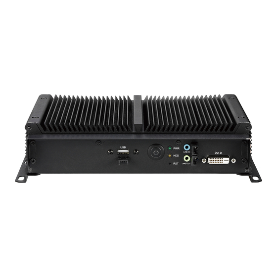
Line-in and line-out ports used to connect audio devices such as speakers and headphones. USB 2.0 Reset Switch DVI-D DVI-D Power Switch Used to connect a DVI-D interface monitor. Copyright © 2017 NEXCOM International Co., Ltd. All Rights Reserved. CE-HW-01/02 User Manual... -
Page 19: Rear
Serial DB9 port used to connect RS232/422/485 compatible devices. DVI-I LAN 1 to LAN 4 USB 2.0 24V DC Input Ports 24V DC Input USB 3.0 Used to plug a DC power cord. Copyright © 2017 NEXCOM International Co., Ltd. All Rights Reserved. CE-HW-01/02 User Manual... -
Page 20: Mechanical Dimensions
Chapter 1: Product Introduction Mechanical Dimensions 262.20 274.20 274.20 Copyright © 2017 NEXCOM International Co., Ltd. All Rights Reserved. CE-HW-01/02 User Manual... -
Page 21: Chapter 2: Jumpers And Connectors
This chapter describes how to set the jumpers and connectors on the dry environments. A grounding strap is warranted whenever danger of motherboard. Note that information in this chapter applies to CE-HW-01/02. static electricity exists. Before You Begin Precautions ▪... -
Page 22: Jumper Settings
Refer to the illustrations below for examples of what the 2-pin and 3-pin jumpers look like when they are short (on) and open (off). Two-Pin Jumpers: Open (Left) and Short (Right) Three-Pin Jumpers: Pins 1 and 2 are Short Copyright © 2017 NEXCOM International Co., Ltd. All Rights Reserved. CE-HW-01/02 User Manual... -
Page 23: Locations Of The Jumpers And Connectors
Chapter 2: Jumpers and Connectors Locations of the Jumpers and Connectors Top View USB1 USB2 LAN1A LAN1D LAN1C LAN1B CN11 SATA1 CN10 Copyright © 2017 NEXCOM International Co., Ltd. All Rights Reserved. CE-HW-01/02 User Manual... -
Page 24: Bottom View
Chapter 2: Jumpers and Connectors Bottom View Copyright © 2017 NEXCOM International Co., Ltd. All Rights Reserved. CE-HW-01/02 User Manual... -
Page 25: Jumpers
Connector location: JP4 Connector location: JP2 Settings Settings 1-2 On Normal 1-2 On VCC3 2-3 On RTC Clear 3-4 On VCC5 1-2 On: default 1-2 On: default Copyright © 2017 NEXCOM International Co., Ltd. All Rights Reserved. CE-HW-01/02 User Manual... -
Page 26: At/Atx Power Select
Chapter 2: Jumpers and Connectors AT/ATX Power Select Connector type: 1x3 3-pin header, 2.0mm pitch Connector location: JP1 Settings 1-2 On AT Mode 2-3 On ATX Mode Copyright © 2017 NEXCOM International Co., Ltd. All Rights Reserved. CE-HW-01/02 User Manual... -
Page 27: Connector Pin Definitions
LAN1_MDI0P LAN1_MDI0N LAN1_MDI1P LAN1_MDI1N LAN1_TCTG LAN1_TCT DVI1_HPD LAN1_MDI2P LAN1_MDI2N DVI1_DATA0_N DVI1_DATA0_P LAN1_MDI3P LAN1_MDI3N VGA_CLK LAN1_LEDACT# 3VSB VGA_DATA LAN1_LINK1G# LAN1_LINK100# DVI1_CLK_P DVI1_CLK_N RED_VGA GREEN_VGA BLUE_VGA HS_VGA VGA_GND VGA_GND Copyright © 2017 NEXCOM International Co., Ltd. All Rights Reserved. CE-HW-01/02 User Manual... -
Page 28: Lan2 Port
LAN2_MDI0N LAN3_MDI0P LAN3_MDI0N LAN2_MDI1P LAN2_MDI1N LAN3_MDI1P LAN3_MDI1N LAN2_TCTG LAN2_TCT LAN3_TCTG LAN3_TCT LAN2_MDI2P LAN2_MDI2N LAN3_MDI2P LAN3_MDI2N LAN2_MDI3P LAN2_MDI3N LAN3_MDI3P LAN3_MDI3N LAN2_LEDACT# 3VSB LAN3_LEDACT# 3VSB LAN2_LINK1G# LAN2_LINK100# LAN3_LINK1G# LAN3_LINK100# Copyright © 2017 NEXCOM International Co., Ltd. All Rights Reserved. CE-HW-01/02 User Manual... -
Page 29: Lan4 Port
USB2N0 LAN4_MDI1P LAN4_MDI1N USB2P0 LAN4_TCTG LAN4_TCT USB3RN1 USB3RP1 LAN4_MDI2P LAN4_MDI2N USB3TN1 LAN4_MDI3P LAN4_MDI3N USB3TP1 LAN4_LEDACT# 3VSB USB2N1 USB2P1 LAN4_LINK1G# LAN4_LINK100# USB3RN2 USB3RP2 USB3TN2 USB3TP2 CHASSIS_GND CHASSIS_GND CHASSIS_GND Copyright © 2017 NEXCOM International Co., Ltd. All Rights Reserved. CE-HW-01/02 User Manual... -
Page 30: Dual Usb 2.0 Port
Connector location: USB1 Connector location: CN2 Definition Definition Definition Definition USB2N2 SP1_DCD SP1_RXD USB2P2 SP1_TXD SP1_DTR USB2N3 ISO_GND SP1_DSR USB2P3 SP1_RTS SP1_CTS CHASSIS_GND CHASSIS_GND SP1_RI CHASSIS_GND CHASSIS_GND CHASSIS_GND CHASSIS_GND Copyright © 2017 NEXCOM International Co., Ltd. All Rights Reserved. CE-HW-01/02 User Manual... -
Page 31: Dvi-D Connector
Definition Definition Definition Definition DVI2_DATA2_N DVI2_DATA2_P AGND LINE_OUT_L LINE_OUT_JD DVI2_CLK LINE_OUT_R LINE_IN_L DVI2_DATA AGND LINE_IN_JD DVI2_DATA1_N DVI2_DATA_1_P LINE_IN_R CHASSIS_GND CHASSIS_GND CHASSIS_GND CHASSIS_GND DVI2_HPD DVI2_DATA0_N DVI2_DATA0_P DVI2_CLK_P DVI2_CLK_N Copyright © 2017 NEXCOM International Co., Ltd. All Rights Reserved. CE-HW-01/02 User Manual... -
Page 32: Internal Connectors
Connector type: 1x10 10-pin header, 1.0mm pitch Connector location: J10 Connector location: J11 Definition Definition Definition Definition EC_SMB_CLK EC_SMB_DATA VCC3 VCC3 LPC_LAD0 LPC_LAD1 LPC_LAD2 LPC_LAD3 LPC_FRAME# LPC_CLK1_DEBUG PLTRST_3P3# Copyright © 2017 NEXCOM International Co., Ltd. All Rights Reserved. CE-HW-01/02 User Manual... -
Page 33: Lvds Channel A Connector
VCC5_VDD VCC5_VDD VCC5_VDD VCC3_VDD LVDSA_DAT1N VCC3_VDD LVDSB_DAT5N LVDSA_DAT0N LVDSA_DAT1P LVDSB_DAT4N LVDS_DAT5P LVDSA_DAT0P VCC3_VDD LVDSB_DAT4P VCC3_VDD LVDSA_CLK1N LVDSB_CLK2N LVDSA_DAT2N LVDSA_CLK1P LVDSB_DAT6N LVDSB_CLK2P LVDSA_DAT2P LVDSB_DAT6P LVDSA_DAT3N LVDSB_DAT7N LVDSA_DAT3P LVDSB_DAT7P Copyright © 2017 NEXCOM International Co., Ltd. All Rights Reserved. CE-HW-01/02 User Manual... -
Page 34: Pwr/Hdd Led Connector
Connector type: 1x4 4-pin header, 1.25mm pitch Connector type: 1x4 4-pin header, 1.25mm pitch Connector location: J1 Connector location: J2 Definition Definition Definition Definition PWRLED# PWRLED 5VSB USB2N6 HDD_LED# HDD_LED USB2P6 Copyright © 2017 NEXCOM International Co., Ltd. All Rights Reserved. CE-HW-01/02 User Manual... -
Page 35: Usb Connector
Connector type: 1x4 4-pin header, 1.25mm pitch Connector type: 1x6 6-pin header, 1.25mm pitch Connector location: J3 Connector location: J5 Definition Definition Definition Definition 5VSB USB2N7 3VSB USB2P7 EC_I2C_DATA EC_I2C_CLK Copyright © 2017 NEXCOM International Co., Ltd. All Rights Reserved. CE-HW-01/02 User Manual... -
Page 36: Touch Control Board Connector
Connector type: 1x8 8-pin header, 1.25mm pitch Connector type: 1x3 3-pin header, 1.0mm pitch Connector location: J7 Connector location: J9 Definition Definition Definition Definition VCC3 EC_I2C_DATA FAN_12V EC_I2C_CLK EC_LED_PWM FAN_12V_FB ATXBT# RSTBTN# Copyright © 2017 NEXCOM International Co., Ltd. All Rights Reserved. CE-HW-01/02 User Manual... -
Page 37: Sata Connector
Connector type: Standard Serial ATA 7P (1.27mm, SATA-M-180) Connector type: 1x2 2-pin header, JST 2.5mm pitch Connector location: SATA1 Connector location: CN4 Definition Definition Definition SATA_TXP2 SATA_TXN2 SATA_RXN2 SATA_RXP2 Copyright © 2017 NEXCOM International Co., Ltd. All Rights Reserved. CE-HW-01/02 User Manual... -
Page 38: Lvds Inverter Connector
Connector type: 1x7 7-pin header, 1.25mm pitch Connector type: 1x4 4-pin header, 1.25mm pitch Connector location: J6 Connector location: J4 Definition Definition Definition Definition USB2N4 BKLTCTRL USB2P4 INV_GND INV_GND BKLTEN INV_GND INV_GND Copyright © 2017 NEXCOM International Co., Ltd. All Rights Reserved. CE-HW-01/02 User Manual... -
Page 39: Battery Connector
Connector type: 1x2 2-pin header, JST 1.25mm pitch Connector type: SIM card slot Connector location: J8 Connector location: CN5 Definition Definition Definition Definition UIM_PWR UIM_RESET UIM_CLK UIM_VPP UIM_DATA Copyright © 2017 NEXCOM International Co., Ltd. All Rights Reserved. CE-HW-01/02 User Manual... -
Page 40: Mini-Pcie Slot
3VSB 1.5V SMB_CLK 1.5V PCIE_TXN SMB_DATA CLKREQ# UIM_PWR PCIE_TXP UIM_DATA USB2N5 PCIE_CLK# UIM_CLK USB2P5 PCIE_CLK UIM_RESET 3VSB UIM_VPP 3VSB DISABLE# PCIE_RESET# 1.5V PCIE_RXP 3VSB PCIE_RXN PCIE_mSATA_SEL 3VSB Copyright © 2017 NEXCOM International Co., Ltd. All Rights Reserved. CE-HW-01/02 User Manual... -
Page 41: Ngff M.2 Sata Connector
NGFF M.2 SATA Connector Connector location: CN10 Definition Definition Definition Definition PCIE_M2_CONFIG3 VCC3 SATA_RXN0 VCC3 SATA_TXN0 SATA_TXP0 PCIE_M2_DAS_DSS# PCIE_M2_Z01 PCIE_M2_CONFIG0 PCIE_M2_Z02 PCIE_M2_CONFIG1 VCC3 VCC3 PCIE_M2_DEVSLP VCC3 PCIE_M2_CONFIG2 SATA_RXP0 Copyright © 2017 NEXCOM International Co., Ltd. All Rights Reserved. CE-HW-01/02 User Manual... -
Page 42: Block Diagram
USB 2.0 Dual Connector (Rear) USB 2.0 4 USB 2.0 Internal JST Connector (Front) USB 2.0 5/6 SATA Connector Mini-PCIe USB 2.0 Internal JST Connector *2 4 Port LAN Connector mSATA Copyright © 2017 NEXCOM International Co., Ltd. All Rights Reserved. CE-HW-01/02 User Manual... -
Page 43: Chapter 3: System Setup
Prior to removing the chassis cover, make sure the unit’s power CAUTION! CAUTION! CAUTION! is off and disconnected from the power sources to prevent electric shock or system damage. 1. Remove the screws around the chassis cover. Copyright © 2017 NEXCOM International Co., Ltd. All Rights Reserved. CE-HW-01/02 User Manual... - Page 44 Chapter 3: System Setup 2. Lift up the back cover. 3. Install the SATA M.2 module into the M.2 slot. M.2 Slot SATA M.2 Module Copyright © 2017 NEXCOM International Co., Ltd. All Rights Reserved. CE-HW-01/02 User Manual...
- Page 45 Chapter 3: System Setup 4. Secure the module with mounting screws. Copyright © 2017 NEXCOM International Co., Ltd. All Rights Reserved. CE-HW-01/02 User Manual...
-
Page 46: Installing A So-Dimm Memory Module
Chapter 3: System Setup Installing a SO-DIMM Memory Module 1. Remove the screws around the chassis cover. Copyright © 2017 NEXCOM International Co., Ltd. All Rights Reserved. CE-HW-01/02 User Manual... - Page 47 Chapter 3: System Setup 2. Lift up the back cover. 3. Locate the DIMM1 slot on the mainboard and install a SO-DIMM module into the slot. DIMM1 Copyright © 2017 NEXCOM International Co., Ltd. All Rights Reserved. CE-HW-01/02 User Manual...
- Page 48 Chapter 3: System Setup 4. To add a second SO-DIMM module, install the module into the DIMM2 slot. DIMM2 Copyright © 2017 NEXCOM International Co., Ltd. All Rights Reserved. CE-HW-01/02 User Manual...
-
Page 49: Installing A Sim Card
Chapter 3: System Setup Installing a SIM Card 1. Remove the screws around the chassis cover. Copyright © 2017 NEXCOM International Co., Ltd. All Rights Reserved. CE-HW-01/02 User Manual... - Page 50 Chapter 3: System Setup 2. Lift up the back cover. 3. Open the cover of the SIM card slot on the mainboard. Copyright © 2017 NEXCOM International Co., Ltd. All Rights Reserved. CE-HW-01/02 User Manual...
- Page 51 Chapter 3: System Setup 4. Install the SIM card. 5. Close the cover of the SIM card slot. Copyright © 2017 NEXCOM International Co., Ltd. All Rights Reserved. CE-HW-01/02 User Manual...
-
Page 52: Installing A Mini Pcie Module
Chapter 3: System Setup Installing a Mini PCIe Module Mini PCIe Module 1. Remove the screws around the chassis cover. Copyright © 2017 NEXCOM International Co., Ltd. All Rights Reserved. CE-HW-01/02 User Manual... - Page 53 Chapter 3: System Setup 2. Lift up the back cover. 3. Install the Mini PCIe module into the Mini PCIe slot. Mini PCIe Mini PCIe Slot Module Copyright © 2017 NEXCOM International Co., Ltd. All Rights Reserved. CE-HW-01/02 User Manual...
- Page 54 If you are installing a half-size Mini PCIe module, before proceeding with the installation, please assemble the module bracket first by following the instructions below: Half-size Mini PCIe Module Antennas RF Cables Copyright © 2017 NEXCOM International Co., Ltd. All Rights Reserved. CE-HW-01/02 User Manual...
- Page 55 1. Align the mounting holes on the Mini PCIe module to the mounting 2. Tighten screws onto the mounting holes to secure the bracket. holes on the module bracket. Mounting Module Holes Bracket Copyright © 2017 NEXCOM International Co., Ltd. All Rights Reserved. CE-HW-01/02 User Manual...
-
Page 56: Installing The Half-Size Mini Pcie Module
Installing the Half-Size Mini PCIe Module 1. Install the half-size Mini PCIe module into the Mini PCIe slot. 2. Secure the module with mounting screws. Mini PCIe Mini PCIe Slot Module Copyright © 2017 NEXCOM International Co., Ltd. All Rights Reserved. CE-HW-01/02 User Manual... -
Page 57: Chapter 4: Bios Setup
4: BIos s haPter etuP This chapter describes how to use the BIOS setup program for CE-HW-01/02. The settings made in the setup program affect how the computer performs. The BIOS screens provided in this chapter are for reference only and may It is important, therefore, first to try to understand all the setup options, and change if the BIOS is updated in the future. -
Page 58: Default Configuration
Powering on the computer and immediately pressing <Del> allows you to enter Setup. Load optimized default values. Press the key to enter Setup: Saves and exits the Setup program. Press <Enter> to enter the highlighted sub-menu Copyright © 2017 NEXCOM International Co., Ltd. All Rights Reserved. CE-HW-01/02 User Manual... - Page 59 When “” appears on the left of a particular field, it indicates that a submenu which contains additional options are available for that field. To display the submenu, move the highlight to that field and press Copyright © 2017 NEXCOM International Co., Ltd. All Rights Reserved. CE-HW-01/02 User Manual...
-
Page 60: Bios Setup Utility
00 to 23. Minute displays minutes from 00 to 59. Second displays PCH Information seconds from 00 to 59. Name LynxPoint-LP ▼ Version 2.17.1246. Copyright (C) 2015 American Megatrends, Inc. Copyright © 2017 NEXCOM International Co., Ltd. All Rights Reserved. CE-HW-01/02 User Manual... -
Page 61: Advanced
Windows series operating systems. If you are using an operating system other than Windows, this problem may occur. To avoid this problem, enable this field to limit the return value to 3 or lesser than 3. Copyright © 2017 NEXCOM International Co., Ltd. All Rights Reserved. CE-HW-01/02 User Manual... - Page 62 Enables or disables the SATA controller. CPU C States Enable CPU C States Support for power saving. It is recommended to keep C3, C6 and C7 all enabled for better power saving. Copyright © 2017 NEXCOM International Co., Ltd. All Rights Reserved. CE-HW-01/02 User Manual...
- Page 63 The XHCI and EHCI ownership change should be claimed by the XHCI and EHCI driver respectively. Device Reset Time-out Selects the USB mass storage device’s start unit command timeout. Copyright © 2017 NEXCOM International Co., Ltd. All Rights Reserved. CE-HW-01/02 User Manual...
- Page 64 Enters the sub-menu of serial port 0 configuration. Onboard Serial Port Mode Configures the serial port mode to RS232, RS422 or RS485. Terminal 120 Ohm Enables or disables serial port terminal resistance. Copyright © 2017 NEXCOM International Co., Ltd. All Rights Reserved. CE-HW-01/02 User Manual...
- Page 65 Mode. FAN Speed 30% under Temp Configures the temperature for the fan speed to operate at 30% efficiency. System Temperature Detects and displays the current system temperature. Copyright © 2017 NEXCOM International Co., Ltd. All Rights Reserved. CE-HW-01/02 User Manual...
-
Page 66: Chipset
ESC: Exit Restore on AC Power Loss Select AC power state when power is re-applied after a power failure. Version 2.17.1246. Copyright (C) 2015 American Megatrends, Inc. Copyright © 2017 NEXCOM International Co., Ltd. All Rights Reserved. CE-HW-01/02 User Manual... - Page 67 Control detection of the Azalia device. Disabled Azalia will be unconditionally disabled Enabled Azalia will be unconditionally enabled Auto Azalia will be enabled if present, disabled otherwise. Copyright © 2017 NEXCOM International Co., Ltd. All Rights Reserved. CE-HW-01/02 User Manual...
- Page 68 GFx. Internal Graphics Keep IGD enabled based on the setup options. DVMT Total Gfx Mem Select DVMT5.0 Total Graphic Memory size used by the Internal Graphics Device. Copyright © 2017 NEXCOM International Co., Ltd. All Rights Reserved. CE-HW-01/02 User Manual...
-
Page 69: Boot
Options for including SATA device check during POST routine. The options are Last Boot HDD Only and All Sata Devices. This menu item is only available when Fast Boot is enabled. Copyright © 2017 NEXCOM International Co., Ltd. All Rights Reserved. CE-HW-01/02 User Manual... -
Page 70: Security
Adjust the boot sequence of the system. Boot Option #1 is the first boot device that the system will boot from, next will be #2 and so forth. Hard Drive BBS Priorities Adjust the boot sequence of legacy devices. Copyright © 2017 NEXCOM International Co., Ltd. All Rights Reserved. CE-HW-01/02 User Manual... -
Page 71: Save & Exit
<Enter>. You may be prompted to confirm again before exiting. Restore Defaults To restore the BIOS to default settings, select this field then press <Enter>. A dialog box will appear. Confirm by selecting Yes. Copyright © 2017 NEXCOM International Co., Ltd. All Rights Reserved. CE-HW-01/02 User Manual... -
Page 72: Appendix A: Power Consumption
Test Data Sys#1 System CE-HW-01/02 Modes +24V Sleep Mode 0.11A Total Watts 2.66W Idle Mode 0.66A Total Watts 15.77W Full-Loading Mode 1.62A Total Watts 38.88W Copyright © 2017 NEXCOM International Co., Ltd. All Rights Reserved. CE-HW-01/02 User Manual... -
Page 73: Appendix B: Watchdog
To set up watchdog time interval to 4 seconds, here are the values that should be filled in each address. 4sec = 400ms (decimal) = 190 (hexadecimal) Address 0x50 0x51 0x52 0x53 Data 0x00 0x00 0x01 0x90 Copyright © 2017 NEXCOM International Co., Ltd. All Rights Reserved. CE-HW-01/02 User Manual... -
Page 74: 1.3 Read Watchdog Time Interval Description
Please note different address cannot read continuously, you should run read Read 0x62 port (check 0x03 output EC will return 0x03. command steps all over again till the last address location. on display) Copyright © 2017 NEXCOM International Co., Ltd. All Rights Reserved. CE-HW-01/02 User Manual... -
Page 75: 1.5 Start Watchdog Description
Write 0x29 to Send stop watchdog >o 0x66 0x29 0x66 command Wait OBF set If setup successfully, Read 0x62 port (check 0x02 output EC will return 0x02. on display) Copyright © 2017 NEXCOM International Co., Ltd. All Rights Reserved. CE-HW-01/02 User Manual...
Need help?
Do you have a question about the CE-HW-01 and is the answer not in the manual?
Questions and answers