
Related Manuals for Nexcom VTC 7252 Series


Summary of Contents for Nexcom VTC 7252 Series
- Page 1 NEXCOM International Co., Ltd. Mobile Computing Solutions Vehicle Telematics Computer VTC 7252 Series User Manual NEXCOM International Co., Ltd. www.nexcom.com Published March 2022...
-
Page 2: Table Of Contents
COM1 RS232 Connector ..............17 COM2 RS232 Connector ..............17 Chapter 2: External Connectors Pinout Description COM3 RS232/RS422/RS485 Connector ..........18 Reset Button ..................5 DIO Connector ................18 LED Indicators ..................5 Copyright © 2021 NEXCOM International Co., Ltd. All Rights Reserved. VTC 7252-7C4IP User Manual... - Page 3 Chapter 4: System Setup Appendix D: Signal Connection of DI/DO Removing the Chassis Cover ..............34 GPIO Pinout Description ................64 Installing a Storage Drive ...............36 Digital Input ..................65 Copyright © 2021 NEXCOM International Co., Ltd. All Rights Reserved. VTC 7252-7C4IP User Manual...
- Page 4 WLAN and mSATA Setting ..............74 Appendix F: Pin Definition for the Multiport Cable Pinout Description .................76 Appendix G: Com Port Table .........77 Appendix H: Power Consumption ......78 Copyright © 2021 NEXCOM International Co., Ltd. All Rights Reserved. VTC 7252-7C4IP User Manual...
-
Page 5: Preface
The product(s) described in this manual complies with all applicable European Union (CE) directives if it has a CE marking. For computer systems VTC 7252-7C4IP is a trademark of NEXCOM International Co., Ltd. All to remain CE compliant, only CE-compliant parts may be used. Maintaining other product names mentioned herein are registered trademarks of their CE compliance also requires proper cable and cabling techniques. -
Page 6: Rohs Compliance
0.1% or 1,000ppm, and Polybrominated diphenyl Ethers (PBDE) < 0.1% or 1,000ppm. In order to meet the RoHS compliant directives, NEXCOM has established an engineering and manufacturing task force in to implement the introduction of green products. The task force will ensure that we follow the standard... -
Page 7: Warranty And Rma
▪ Replace with 3rd party products if needed. encountered and note anything abnormal or, print out any on-screen ▪ If RMA goods can not be repaired, NEXCOM will return it to the customer messages, and describe the problems on the “NEXCOM RMA Service without any charge. - Page 8 Always power off the system before inserting or removing the SIM only with the same or equivalent type recommended by the manufacturer. card. Discard used batteries according to the manufacturer’s instructions. viii Copyright © 2021 NEXCOM International Co., Ltd. All Rights Reserved. VTC 7252-7C4IP User Manual...
- Page 9 ACCORDING TO THE MANUFACTURER’S INSTRUCTIONS. rating marked on the product. ▪ All cautions and warnings on the equipment should be noted. Copyright © 2021 NEXCOM International Co., Ltd. All Rights Reserved. VTC 7252-7C4IP User Manual...
-
Page 10: Technical Support And Assistance
Preface Technical Support and Assistance Conventions Used in this Manual 1. For the most updated information of NEXCOM products, visit NEXCOM’s Warning: website at www.nexcom.com. Information about certain situations, which if not observed, can cause personal injury. This will prevent injury to yourself 2. -
Page 11: Global Service Contact Information
Tel: +886-2-8226-7786 Tel: +886-2-8976-3077 Beitun District, Fax: +886-2-8226-7782 Email: sales@diviotec.com Taichung City, 406, Taiwan, R.O.C. Email: services@tmrtek.com www.diviotec.com Tel: +886-4-2249-1179 www.tmrtek.com Fax: +886-4-2249-1172 Email: jacobhuang@nexaiot.com www.nexaiot.com Copyright © 2021 NEXCOM International Co., Ltd. All Rights Reserved. VTC 7252-7C4IP User Manual... - Page 12 9F, Tamachi Hara Bldg., LongGang District, 4-11-5, Shiba Minato-ku, ShenZhen, 518112, China Tokyo, 108-0014, Japan Tel: +86-755-8364-7768 Tel: +81-3-5419-7830 Fax: +86-755-8364-7738 Fax: +81-3-5419-7832 Email: steveyang@nexcom.com.tw Email: sales@nexcom-jp.com www.nexcom.cn www.nexcom-jp.com Copyright © 2021 NEXCOM International Co., Ltd. All Rights Reserved. VTC 7252-7C4IP User Manual...
-
Page 13: Package Contents
Mini Card Heatsink For VTC7252-7C4IP VER:A SHYUNG 5050301015X00 SHUHNΦ20x18mm AL5052 5060200181X00 Thermal Pad E-LIN 25x25x2mm S3S K=2.0w/mk (H)Round Head Screw w/Spring+Flat Washer Long 50311F0270X00 Fei:P3x7L P3x7 iso/SW6x0.5 NI xiii Copyright © 2021 NEXCOM International Co., Ltd. All Rights Reserved. VTC 7252-7C4IP User Manual... -
Page 14: Ordering Information
802.3af/at (total 60W), 2 x mini-PCIe slot, 2 x M.2 slot, 2 x SIM socket, 2 x USB 3.1, 2 x RS232 (full), 1 x full RS232/422/485, 3 x DI & 3 x DO Copyright © 2021 NEXCOM International Co., Ltd. All Rights Reserved. VTC 7252-7C4IP User Manual... -
Page 15: Chapter 1: Product Introduction
2 x Micro SIM Reset CFast Button USB 3.1 USB 2.0 LAN1 LAN2 PoE1 to PoE4 Input COM3 COM2 COM1 Antenna GNSS Antenna Indicators Connectors Connector Multiport Audio Copyright © 2021 NEXCOM International Co., Ltd. All Rights Reserved. VTC 7252-7C4IP User Manual... -
Page 16: Hardware Specifications
▪ 1 x M.2 2230 Key E (USB 2.0, 2 x PCIe 3.0) for Wi-Fi. (BOM option) 1 x Full size mini-PCIe socket (USB 2.0, PCIe 3.0) - 3 x DI, and 3 x DO - GND Copyright © 2021 NEXCOM International Co., Ltd. All Rights Reserved. VTC 7252-7C4IP User Manual... - Page 17 ▪ E-Mark (E13) Operating System ▪ IP65 Compliance ▪ Windows 10 ▪ Linux Dimensions ▪ 256 x 256.4 x 66.5 (W x D x H) (mm) Copyright © 2021 NEXCOM International Co., Ltd. All Rights Reserved. VTC 7252-7C4IP User Manual...
-
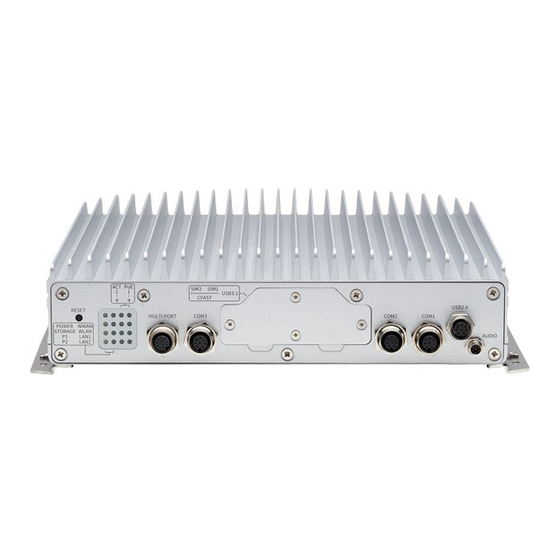
Page 18: Connector Numbering
2 of the manual. Front View Rear View Copyright © 2021 NEXCOM International Co., Ltd. All Rights Reserved. VTC 7252-7C4IP User Manual... -
Page 19: Chapter 2: External Connectors Pinout Description
WWAN PoE ACT1 PoE PWR1 Storage WLAN PoE ACT2 PoE PWR2 RST_BTN# Program 1 LAN1 PoE ACT3 PoE PWR3 Program 2 LAN2 PoE ACT4 PoE PWR4 Copyright © 2021 NEXCOM International Co., Ltd. All Rights Reserved. VTC 7252-7C4IP User Manual... -
Page 20: M12 Multiport Connector
Connector Number: 3 Connector Number: 4 12 11 Definition Definition Definition Definition DCD (TX-) RX (TX+) TX (RX+) DTR (RX+) CAN1 L CAN1 H CAN2 L CAN2 H Copyright © 2021 NEXCOM International Co., Ltd. All Rights Reserved. VTC 7252-7C4IP User Manual... -
Page 21: Cfast Card Slot
SATA-TXP USB_5N SATA-TXN USB_5P SATA-RXN SATA-RXP USB3_RX5N USB3_RX5P USB3_TX5N USB3_TX5P USB_6N USB_6P USB3_RX6N USB3_RX6P PC10 PC11 USB3_TX6N USB3_TX6P PC12 PC13 CFAST_VCC3 PC14 CFAST_VCC3 PC15 PC16 PC17 Copyright © 2021 NEXCOM International Co., Ltd. All Rights Reserved. VTC 7252-7C4IP User Manual... -
Page 22: Micro Sim1/Sim2 Slots
Micro SIM1/SIM2 Slots M12 COM2 Connector Connector number: 7 Connector Number: 8 Definition Definition Definition Definition UIM_PWR DCD (TX-) RX (TX+) UIM_RST TX (RX+) DTR (RX+) UIM_CLK UIM_DAT Copyright © 2021 NEXCOM International Co., Ltd. All Rights Reserved. VTC 7252-7C4IP User Manual... -
Page 23: M12 Com1 Connector
M12 USB 2.0 Connector Connector Number: 9 Connector Number: 10 Definition Definition Definition Definition DCD (TX-) RX (TX+) USB_3N USB_3P TX (RX+) DTR (RX+) USB20_POWER USB_4N USB_4P USB20_POWER Copyright © 2021 NEXCOM International Co., Ltd. All Rights Reserved. VTC 7252-7C4IP User Manual... -
Page 24: M12 Audio Connector
Connector number: 12 4 3 2 Definition Definition Definition Definition MIC_Jdetect VGA_RED VGA_GREEN MIC_L Line out_R VGA_BLUE Line out_Jdetect Line out_L VGA_+5V VGA_DATA VGA_HS VGA_VS VGA_CLK Copyright © 2021 NEXCOM International Co., Ltd. All Rights Reserved. VTC 7252-7C4IP User Manual... -
Page 25: M12 Lan1 & Lan2 Connector
Connector Number: 13 & 14 Connector Number: 15 to 18 Definition Definition Definition Definition LAN_MDI0P LAN_MDI0N LAN_MDI0P LAN_MDI0N LAN_MDI1P LAN_MDI1N LAN_MDI1P LAN_MDI1N LAN_MDI2P LAN_MDI2N LAN_MDI2P LAN_MDI2N LAN_MDI3P LAN_MDI3N LAN_MDI3P LAN_MDI3N Copyright © 2021 NEXCOM International Co., Ltd. All Rights Reserved. VTC 7252-7C4IP User Manual... -
Page 26: Dc Input
Chapter 2: External Connectors Pinout Description DC Input Connector Number: 19 Definition Definition GND_IN GND_IN IGNITION Copyright © 2021 NEXCOM International Co., Ltd. All Rights Reserved. VTC 7252-7C4IP User Manual... -
Page 27: Chapter 3: Jumpers And Connectors
Humid environment tend to have less static electricity than ▪ Use correct screws and do not over tighten screws. dry environments. A grounding strap is warranted whenever danger of static electricity exists. Copyright © 2021 NEXCOM International Co., Ltd. All Rights Reserved. VTC 7252-7C4IP User Manual... -
Page 28: Jumper Settings
(on) and open (off). Two-Pin Jumpers: Open (Left) and Short (Right) Three-Pin Jumpers: Pins 1 and 2 are Short Copyright © 2021 NEXCOM International Co., Ltd. All Rights Reserved. VTC 7252-7C4IP User Manual... - Page 29 The figure below is the carrier board used in the VTC 7252-7C4IP system. It shows the locations of the jumpers and connectors. CN11 CN16 CN18 CN19 Copyright © 2021 NEXCOM International Co., Ltd. All Rights Reserved. VTC 7252-7C4IP User Manual...
-
Page 30: Jumper And Dip Switch Settings
Input Voltage Control Selection Connector location: SW1 Connector location: SW4 RTC (Pin1) SRTC/ME (Pin2) POWERSW (Pin1) 12V24V (Pin2) Result Normal Normal 12VDC Clear CMOS Clear ME 24VDC 9~36VDC (Default) Copyright © 2021 NEXCOM International Co., Ltd. All Rights Reserved. VTC 7252-7C4IP User Manual... -
Page 31: Internal Connectors
Connector location: J3 Connector location: J2 Definition Definition Definition Definition SP_CTS1 SP_DSR1 SP_CTS2 SP_DSR2 SP_DTR1 SP_RXD1 SP_DTR2 SP_RXD2 SP_RI1 SP_RTS1 SP_RI2 SP_RTS2 SP_TXD1 SP_DCD1 SP_TXD2 SP_DCD2 Copyright © 2021 NEXCOM International Co., Ltd. All Rights Reserved. VTC 7252-7C4IP User Manual... -
Page 32: Com3 Rs232/Rs422/Rs485 Connector
Connector size: 1 x 10 = 10-pin header Connector location: J1 Connector location: J24 Definition Definition Definition Definition CM3_CTS# CM3_DSR# CM3_DTR#_RX- CM3_RX_TX+ CM3_RI#_PW CM3_RTS# CM3_TX_RX+ CM3_DCD#_TX- Copyright © 2021 NEXCOM International Co., Ltd. All Rights Reserved. VTC 7252-7C4IP User Manual... -
Page 33: Audio Phone Jack
Front_out_L / Surr_out_L Front_out_JD / Surr_out_JD HDMI_GND HDMI_HPD Front_out_R / Surr_out_R MIC_L / MIC_R HDMI_P5V MIC_JD AGND HDMI_SDA HDMI_SCL HDMI_CLK_N HDMI_CLK_P HDMI_TX0N HDMI_TX0P HDMI_TX1N HDMI_TX1P HDMI_TX2N HDMI_TX2P Copyright © 2021 NEXCOM International Co., Ltd. All Rights Reserved. VTC 7252-7C4IP User Manual... -
Page 34: Sata Connector 1
Connector size: 1 x 7 = 7-pin header Connector location: CN3 Connector location: CN11 Definition Definition Definition Definition SATA-TXP0 SATA-TXP1 SATA-TXN0 SATA_PCIE_DETP0 SATA-TXN1 SATA_PCIE_DETP1 SATA-RXN0 SATA-RXP0 SATA-RXN1 SATA-RXP1 Copyright © 2021 NEXCOM International Co., Ltd. All Rights Reserved. VTC 7252-7C4IP User Manual... -
Page 35: Gps Wire To Board Connector
Connector size: 1 x 6 = 6-pin header Connector size: 1 x 4 = 4-pin header Connector location: J13 Connector location: J4 Definition Definition Definition Definition 3.3V_BAT ODOMETER DIRECTION 3.3V Copyright © 2021 NEXCOM International Co., Ltd. All Rights Reserved. VTC 7252-7C4IP User Manual... -
Page 36: Gps Battery Connector
Connector size: 1 x 2 = 2-pin header Connector size: 1 x 3 = 3-pin header Connector location: J14 Connector location: J23 Definition Definition Definition ODOMETER DIRECTION VBAT Copyright © 2021 NEXCOM International Co., Ltd. All Rights Reserved. VTC 7252-7C4IP User Manual... -
Page 37: Rtc Battery Connector
Connector size: 1 x 10 = 10-pin header Connector location: J15 Connector location: J17 Definition Definition Definition PLTRST# VBAT LPC_CLK LPC_FRAME# LPC_AD3 LPC_AD2 LPC_AD1 LPC_AD0 LPC_SERIRQ VCC3 Copyright © 2021 NEXCOM International Co., Ltd. All Rights Reserved. VTC 7252-7C4IP User Manual... -
Page 38: Usb Connectors
Connector size: 1 x 3 = 3-pin header Connector location: J5, J6, J7, J8, J9 and J10 Connector location: JP3 Definition Definition Definition USB_P USB_N POWER Copyright © 2021 NEXCOM International Co., Ltd. All Rights Reserved. VTC 7252-7C4IP User Manual... -
Page 39: Mcu Download Port
Connector size: 1 x 4 = 4-pin header Connector location: JP2 Connector location: J22 Definition Definition Definition Definition 3.3V MCU_RST CAN2_H CAN2_L MCU_TRST MCU_TDI CAN1_H MCU_TCK MCU_TMS CAN1_L MCU_TDO Copyright © 2021 NEXCOM International Co., Ltd. All Rights Reserved. VTC 7252-7C4IP User Manual... -
Page 40: Can1 Download Connector
Connector size: 1 x 6 = 6-pin header Connector size: 1 x 6 = 6-pin header Connector location: J21 Connector location: J20 Definition Definition Definition Definition VCC3 VCC3 Copyright © 2021 NEXCOM International Co., Ltd. All Rights Reserved. VTC 7252-7C4IP User Manual... -
Page 41: V2X Power Connector
Connector size: 1 x 2 = 2-pin header Connector size: 2 x 4 = 8-pin header Connector location: J19 Connector location: CN7 Definition Definition Definition 5VDC 12VDC PUSH_BTN_PWRIN EXT_RX EXT_TX PUSH_BT_SLEEPIN PUSH_BTN_RSTIN Copyright © 2021 NEXCOM International Co., Ltd. All Rights Reserved. VTC 7252-7C4IP User Manual... -
Page 42: Power Button Connector
Chapter 3: Jumpers and Connectors Power Button Connector Connector size: 1 x 2 = 2-pin header Connector location: CN19 Definition HW_BT# Copyright © 2021 NEXCOM International Co., Ltd. All Rights Reserved. VTC 7252-7C4IP User Manual... -
Page 43: Key E Socket With Usb 2.0 + 2 X Pcie 3.0 (For Wi-Fi/Bt)
M2E_SUSCLK PCIE0_REFCLKN (NC_BOM Option) PERST0#_M2_3P3 CLKREQ0#_M2_3P3 M2E_DISABLE2# M2E_DISABLE1# M2E_LED2# PCIE1_TXP PCIE1_TXN I2C_ALERT#_M2_3P3 PCIE1_RXP PERST1#_M2_3P3 PCIE1_RXN CLKREQ#_M2_3P3 PCIE0_TXP PCIE1_REFCLKP +V3.3A PCIE0_TXN TPU_SYS_RSTN_EN PCIE1_REFCLKN +V3.3A PMIC0_EN_M2_OD_3P3 PCIE0_RXP PMIC1_EN_M2_OD_3P3 Copyright © 2021 NEXCOM International Co., Ltd. All Rights Reserved. VTC 7252-7C4IP User Manual... -
Page 44: (Bom Optional)
Connector location: CN8 Definition Definition Definition Definition +V1.5S RI (NC) +V3.3A PCIE_TXN +V1.5S PCIE_TXP PCIE_CLKREQ# USB_D- USB_D+ PCIE_CLKN +V3.3A PCIE_CLKP +V3.3A MINIPCIE2_DIS# +V1.5S P2_RST# PCIE_RXN +V3.3A +V3.3A PCIE_RXP Copyright © 2021 NEXCOM International Co., Ltd. All Rights Reserved. VTC 7252-7C4IP User Manual... -
Page 45: Full-Size Mini-Pcie Socket With Usb 2.0 + Pcie 3.0/Sata 3.0 (For Wi-Fi/Bt/Msata/C-V2X/Dsrc)
BIOS setup menu for CN18. Definition Definition Definition Definition +V3.3A +V1.5S +V1.5S PCIE_TXN PCIE_CLKREQ# PCIE_TXP USB_D- PCIE_CLKN USB_D+ PCIE_CLKP +V3.3A +V3.3A MINIPCIE2_DIS# P2_RST# +V1.5S PCIE_RXN +V3.3A PCIE_RXP MSATA_DET# +V3.3A Copyright © 2021 NEXCOM International Co., Ltd. All Rights Reserved. VTC 7252-7C4IP User Manual... -
Page 46: Full-Size Mini-Pcie Socket With Usb 2.0 + Pcie 3.0/Sata 3.0 (For Wi-Fi/Bt/Msata)
Connector location: CN18 Definition Definition Definition Definition +V3.3A +V1.5S +V1.5S PCIE_TXN PCIE_CLKREQ# PCIE_TXP USB_D- PCIE_CLKN USB_D+ PCIE_CLKP +V3.3A +V3.3A MINIPCIE2_DIS# P2_RST# +V1.5S PCIE_RXN +V3.3A PCIE_RXP MSATA_DET# +V3.3A Copyright © 2021 NEXCOM International Co., Ltd. All Rights Reserved. VTC 7252-7C4IP User Manual... -
Page 47: 3042/3050/3052 Key B Socket With Usb 2.0 + Usb 3.2 Gen 2×1 (For Lte/5G Nr)
M2B1_SM1_C PLA_S2# USB3_RXN UIM1_RST USB3_RXP UIM1_CLK UIM1_DAT SIM1_DETECT USB3_TXN UIM1_PWR P1_3.5G_RST# M2A_SUSCLK USB3_TXP EM9190_P2 M2A_CONFIG1 +V3.3A SIM2_DETECT +V3.3A PCIE_RXN UIM2_DAT +V3.3A (NC_BOM Option) (NC_BOM Option) M2A_CONFIG2 Copyright © 2021 NEXCOM International Co., Ltd. All Rights Reserved. VTC 7252-7C4IP User Manual... -
Page 48: Chapter 4: System Setup
1. Remove the screws on the front panel. 2. Remove the screws on the rear panel. Copyright © 2021 NEXCOM International Co., Ltd. All Rights Reserved. VTC 7252-7C4IP User Manual... - Page 49 3. Remove the mounting bracket screws on the bottom of the enclosure. 4. After removing the brackets, loosen the screws on the bottom then remove the chassis top cover. Copyright © 2021 NEXCOM International Co., Ltd. All Rights Reserved. VTC 7252-7C4IP User Manual...
-
Page 50: Installing A Storage Drive
2. Align the mounting holes on the storage drives to the mounting holes bracket. on the bracket, then turn to the bottom side of the bracket and use the provided screws to secure the storage drives in place. Copyright © 2021 NEXCOM International Co., Ltd. All Rights Reserved. VTC 7252-7C4IP User Manual... -
Page 51: Installing A Wwan Module (M.2)
45 degrees angle until the gold-plated connector on the edge of the module completely disappears inside the slot. Then fasten a screw into the mounting hole to secure the module. Copyright © 2021 NEXCOM International Co., Ltd. All Rights Reserved. VTC 7252-7C4IP User Manual... -
Page 52: Installing A Wi-Fi Module (M.2)
Then fasten a screw into the mounting hole to secure the module. Copyright © 2021 NEXCOM International Co., Ltd. All Rights Reserved. VTC 7252-7C4IP User Manual... -
Page 53: Installing A Wi-Fi/Msata Module (Mini-Pcie)
Then fasten a screw into the mounting hole to secure the module. mSATA Module Wi-Fi Module Please be noted that you have to select the mSATA setting in the BIOS setup menu for CN18. Copyright © 2021 NEXCOM International Co., Ltd. All Rights Reserved. VTC 7252-7C4IP User Manual... -
Page 54: Installing A So-Dimm Memory Module
Apply firm even pressure to each end of the module until it slips down into the socket. The contact fingers on the edge of the module will almost completely disappear inside the socket. Copyright © 2021 NEXCOM International Co., Ltd. All Rights Reserved. VTC 7252-7C4IP User Manual... -
Page 55: Inserting Sim Cards
Please take note of the Micro SIM card installation direction as printed on the chassis. Installation direction for top slot Installation direction for top slot Copyright © 2021 NEXCOM International Co., Ltd. All Rights Reserved. VTC 7252-7C4IP User Manual... -
Page 56: Inserting A Cfast Card
1. Remove the SIM/CFast card cover on the front panel and insert the CFast card. Please take note of the CFast card installation direction as printed on the chassis. Installation direction for top slot Copyright © 2021 NEXCOM International Co., Ltd. All Rights Reserved. VTC 7252-7C4IP User Manual... -
Page 57: Installing Heatsink For Lte/5G And Msata Modules
2. Before adding heatsink for LTE/5G or mSATA module, remove the cover slop upwards from the chassis before opening the bottom cover. screws on the front panel. Copyright © 2021 NEXCOM International Co., Ltd. All Rights Reserved. VTC 7252-7C4IP User Manual... - Page 58 3. If using LTE/5G or mSATA module, fix the heatsink by using screws. 4. If LTE/5G and mSATA modules are used simultaneously, fix two heat- sinks by using screws. Copyright © 2021 NEXCOM International Co., Ltd. All Rights Reserved. VTC 7252-7C4IP User Manual...
- Page 59 6. Make sure the thermal pad is attached on the module firmly. heatsinks by using screws and attach thermal pads on the top of the heatsinks. Copyright © 2021 NEXCOM International Co., Ltd. All Rights Reserved. VTC 7252-7C4IP User Manual...
- Page 60 7. In order to protect the water seal strip on the rear panel, make sure 8. Fasten the screws on the front panel. the bottom cover slopes downward of the chassis before closing the bottom cover. Copyright © 2021 NEXCOM International Co., Ltd. All Rights Reserved. VTC 7252-7C4IP User Manual...
-
Page 61: Appendix A: Software Demo Utility For I/O Ports Of Function Control
NEXCOM’s software demo utility enables users to test and control different I/O port functions on VTC 7252. This section shows how to use the utility. There are also source code files of the utility in the CD. Users can refer to the source codes to develop their applications. - Page 62 ▪ If the setting is 24V: 24V is shown. ▪ If the setting is 9V~36V: 9V~36V is shown. 1.3 Low Battery Voltage Protection Sets the Low Battery Voltage Protection Startup/Shutdown voltage level during 12V/24V. Copyright © 2021 NEXCOM International Co., Ltd. All Rights Reserved. VTC 7252-7C4IP User Manual...
-
Page 63: System 2
2.3 Watchdog Timer Enables or disables the WDT function. There are several selections of time. The timer of WDT can also be cleared by the Set WDT button. Copyright © 2021 NEXCOM International Co., Ltd. All Rights Reserved. VTC 7252-7C4IP User Manual... -
Page 64: I/O
3.2 GPO Configures GPO as high voltage level or low voltage level. 3.3 GPI Active Mode Reads the status (High or Low) of GPI active mode. Copyright © 2021 NEXCOM International Co., Ltd. All Rights Reserved. VTC 7252-7C4IP User Manual... - Page 65 3.7 Programmable LED Defines the programmable LEDs as ON or OFF. 3.5 Wake on LAN Enables or disables the Wake On LAN function on LAN (Intel i219). Copyright © 2021 NEXCOM International Co., Ltd. All Rights Reserved. VTC 7252-7C4IP User Manual...
-
Page 66: Module
Selects whether the SIM card setting on WWAN is from SIM card 1 or SIM card 2. The setting can also be cleared by the Set button. Copyright © 2021 NEXCOM International Co., Ltd. All Rights Reserved. VTC 7252-7C4IP User Manual... - Page 67 Selects the slot type (SATA/USB/PCIe) on the CN18 mini PCIe socket. 4.4 Bluetooth Enables or disables the BT function on the CN18 mini PCIe socket. The setting can also be cleared by the Set button. Copyright © 2021 NEXCOM International Co., Ltd. All Rights Reserved. VTC 7252-7C4IP User Manual...
-
Page 68: Poe
1. Press the Power On button or Power Off button to turn on or turn off 2. Lower voltage alarm PoE power ouput. 2. Show the power output (watt) of each PoE port and total power output. Copyright © 2021 NEXCOM International Co., Ltd. All Rights Reserved. VTC 7252-7C4IP User Manual... -
Page 69: Can Utility
CAN-bus. 7.3 Self Test Mode In Self Test Mode, a full node test is possible without any other active node on the bus. Copyright © 2021 NEXCOM International Co., Ltd. All Rights Reserved. VTC 7252-7C4IP User Manual... - Page 70 7.7 Other Info send those CAN information. Shows the statistics of sent messages. Shows the statistics of the sent error messages. Shows the statistics of received messages. Copyright © 2021 NEXCOM International Co., Ltd. All Rights Reserved. VTC 7252-7C4IP User Manual...
-
Page 71: G-Sensor
X-Axis data, Y-Axis data and Z-Axis data can be get by pressing the Set button. 8.3 Sensor Register Index Selects the registers inside the sensor to read or write the data. Copyright © 2021 NEXCOM International Co., Ltd. All Rights Reserved. VTC 7252-7C4IP User Manual... - Page 72 Appendix A: Software Demo Utility for I/O Ports of Function Control 8.4 Register Table Shows the value of all registers in the sensor, once the Refresh button is pressed. Copyright © 2021 NEXCOM International Co., Ltd. All Rights Reserved. VTC 7252-7C4IP User Manual...
-
Page 73: Appendix B: Gnss Feature
Qualification tests are performed as stipulated in the ISO16750 lowest noise figure (NEO-M8N/Q) standard: “Road vehicles – Environmental conditions and testing for electrical and electronic equipment”. Copyright © 2021 NEXCOM International Co., Ltd. All Rights Reserved. VTC 7252-7C4IP User Manual... - Page 74 C compliant) Baud Rate: 9600 Digital I/O Configurable timepulse 1 EXTINT input for Wakeup Timepulse Configurable 0.25 Hz to 10 MHz Protocols NMEA, UBX binary, RTCM Copyright © 2021 NEXCOM International Co., Ltd. All Rights Reserved. VTC 7252-7C4IP User Manual...
-
Page 75: Appendix C: Gnss With Dead Reckoning Feature
3D sensing also enables flexibility in orientation of the receiver with respect to the vehicle frame. With future flash firmware update. Copyright © 2021 NEXCOM International Co., Ltd. All Rights Reserved. VTC 7252-7C4IP User Manual... -
Page 76: Technical Specifications
Dependent on signal conditions but measurements are delivered with time-stamp corresponding to measurement time Maximum navigation Higher bandwidths are used for navigation rate 20 Hz Assuming Airborne < 4 g platform (High Rate output) Copyright © 2021 NEXCOM International Co., Ltd. All Rights Reserved. VTC 7252-7C4IP User Manual... - Page 77 J4 Pin Definition J13 Pin Definition Definition Definition Definition Definition 1PPS 3.3V GPS LED DR_ODOMETER_M DR_DIRECTIO_M 3.3V COM Port for GNSS: COM 4 Baud Rate: 9600 Copyright © 2021 NEXCOM International Co., Ltd. All Rights Reserved. VTC 7252-7C4IP User Manual...
-
Page 78: Appendix D: Signal Connection Of Di/Do
Appendix D: Signal Connection of DI/DO d: s dI/do PPendIx IGnal onneCtIon of GPIO Pinout Description 12 11 Definition Definition CAN1 L CAN1 H CAN2 L CAN2 H Copyright © 2021 NEXCOM International Co., Ltd. All Rights Reserved. VTC 7252-7C4IP User Manual... -
Page 79: Digital Input
External Internal Sourcing (Default) Internal External 1: GPI1 2: GPI2 3: GPI3 1: GPI1 2: GPI2 3: GPI3 10: GND 12 11 10: GND 12 11 Copyright © 2021 NEXCOM International Co., Ltd. All Rights Reserved. VTC 7252-7C4IP User Manual... -
Page 80: Digital Output
5: GPO1 Note: Example of GPO 1 and GPO 2 as a pair, and GPO 3 as a single. 6: GPO2 7: GPO3 10: GND 12 11 Copyright © 2021 NEXCOM International Co., Ltd. All Rights Reserved. VTC 7252-7C4IP User Manual... - Page 81 The figure below shows how to connect an external input source to one of the output channels. External Sourcing Internal External 5: GPO1 6: GPO2 7: GPO3 10: GND 12 11 Copyright © 2021 NEXCOM International Co., Ltd. All Rights Reserved. VTC 7252-7C4IP User Manual...
-
Page 82: Appendix E: Vehicle Power Management Setup
F4: Save & Exit F4: Save & Exit ESC: Exit ESC: Exit Version 2.20.1275. Copyright (C) 2019 American Megatrends, Inc. Version 2.20.1275. Copyright (C) 2019 American Megatrends, Inc. Copyright © 2021 NEXCOM International Co., Ltd. All Rights Reserved. VTC 7252-7C4IP User Manual... - Page 83 F4: Save & Exit F4: Save & Exit ESC: Exit ESC: Exit Version 2.20.1275. Copyright (C) 2019 American Megatrends, Inc. Version 2.20.1275. Copyright (C) 2019 American Megatrends, Inc. Copyright © 2021 NEXCOM International Co., Ltd. All Rights Reserved. VTC 7252-7C4IP User Manual...
-
Page 84: Power-On Delay Setting
+/-: Change Opt. F1: General Help F2: Previous Values F3: Optimized Defaults F4: Save & Exit ESC: Exit Version 2.20.1275. Copyright (C) 2019 American Megatrends, Inc. Copyright © 2021 NEXCOM International Co., Ltd. All Rights Reserved. VTC 7252-7C4IP User Manual... - Page 85 F4: Save & Exit F4: Save & Exit ESC: Exit ESC: Exit Version 2.20.1275. Copyright (C) 2019 American Megatrends, Inc. Version 2.20.1275. Copyright (C) 2019 American Megatrends, Inc. Copyright © 2021 NEXCOM International Co., Ltd. All Rights Reserved. VTC 7252-7C4IP User Manual...
-
Page 86: Power-Off Delay Setting
+/-: Change Opt. F1: General Help F2: Previous Values F3: Optimized Defaults F4: Save & Exit ESC: Exit Version 2.20.1275. Copyright (C) 2019 American Megatrends, Inc. Copyright © 2021 NEXCOM International Co., Ltd. All Rights Reserved. VTC 7252-7C4IP User Manual... - Page 87 F4: Save & Exit F4: Save & Exit ESC: Exit ESC: Exit Version 2.20.1275. Copyright (C) 2019 American Megatrends, Inc. Version 2.20.1275. Copyright (C) 2019 American Megatrends, Inc. Copyright © 2021 NEXCOM International Co., Ltd. All Rights Reserved. VTC 7252-7C4IP User Manual...
-
Page 88: Wlan And Msata Setting
F4: Save & Exit F4: Save & Exit ESC: Exit ESC: Exit Version 2.20.1275. Copyright (C) 2021 American Megatrends, Inc. Version 2.20.1275. Copyright (C) 2021 American Megatrends, Inc. Copyright © 2021 NEXCOM International Co., Ltd. All Rights Reserved. VTC 7252-7C4IP User Manual... -
Page 89: Appendix F: Pin Definition For The Multiport Cable
Appendix F: Pin Definition for the Multiport Cable f: P PPendIx efInItIon for the ultIPort aBle 12 11 Copyright © 2021 NEXCOM International Co., Ltd. All Rights Reserved. VTC 7252-7C4IP User Manual... -
Page 90: Pinout Description
Appendix F: Pin Definition for the Multiport Cable Pinout Description Copyright © 2021 NEXCOM International Co., Ltd. All Rights Reserved. VTC 7252-7C4IP User Manual... -
Page 91: Appendix G: Com Port Table
Appendix G: COM Port Table G: C PPendIx aBle COM Port Function COM 1 RS232 COM 2 RS232 COM 3 RS232 / 422 / 485 COM 4 GNSS COM 6 Copyright © 2021 NEXCOM International Co., Ltd. All Rights Reserved. VTC 7252-7C4IP User Manual... -
Page 92: Appendix H: Power Consumption
Pass/Fail Criteria: 1. Start all of the functions on VTC 7252-7C4IP and measure power consumption. 2. Set the system into suspend mode and measure power consumption. Copyright © 2021 NEXCOM International Co., Ltd. All Rights Reserved. VTC 7252-7C4IP User Manual... - Page 93 87.12 5.01 120.24 2.44 87.84 3.53 127.08 12.97 155.64 17.59 211.08 Full State + Loading 6.51 156.24 7.86 188.64 (+ PoE 60W) 3.93 155.52 5.22 187.92 Copyright © 2021 NEXCOM International Co., Ltd. All Rights Reserved. VTC 7252-7C4IP User Manual...
- Page 94 12V wake up 0.07 0.84 WWAN 0.057 1.368 Full State IGN OFF 24V wake up IGNITION OFF 0.079 1.896 WWAN 0.084 3.024 36V wake up 0.103 3.708 WWAN Copyright © 2021 NEXCOM International Co., Ltd. All Rights Reserved. VTC 7252-7C4IP User Manual...
Need help?
Do you have a question about the VTC 7252 Series and is the answer not in the manual?
Questions and answers