
Related Manuals for Nexcom VTC 6100


Summary of Contents for Nexcom VTC 6100
-
Page 1: User Manual
NEXCOM International Co., Ltd. Mobile Computing Solutions Vehicle Telematics Computer VTC 6100 User Manual NEXCOM International Co., Ltd. www.nexcom.com Published March 2009... -
Page 2: Table Of Contents
COM Express Row C and Row D ............20 Physical Features ..................6 CompactFlash Connector..............22 Front Panel ...................6 GPIO Connector .................23 Rear Panel ....................8 RS232 Connector: COM1, COM2 ............23 Mechanical Dimensions .................12 Copyright © 2009 NEXCOM International Co., Ltd. All Rights Reserved. VTC 6100 User Manual... - Page 3 Appendix E: Power Consumption Chapter 3: System Setup Power Consumption ................103 Removing the Chassis Cover ..............38 Installing a GPRS/UMTS/HSDPA Module ..........39 Installing a Wireless LAN Module ............42 Copyright © 2009 NEXCOM International Co., Ltd. All Rights Reserved. VTC 6100 User Manual...
-
Page 4: Preface
Acknowledgements The product(s) described in this manual complies with all applicable Euro- VTC 6100 is a trademark of NEXCOM International Co., Ltd. All other pean Union (CE) directives if it has a CE marking. For computer systems to product names mentioned herein are registered trademarks of their respec- remain CE compliant, only CE-compliant parts may be used. -
Page 5: Rohs Compliance
0.1% or 1,000ppm, and Polybrominated diphenyl Ethers (PBDE) < 0.1% or 1,000ppm. In order to meet the RoHS compliant directives, NEXCOM has established an engineering and manufacturing task force in to implement the introduction of green products. The task force will ensure that we follow the standard... -
Page 6: Warranty And Rma
Replace with 3rd party products if needed. the RMA number apply process. If RMA goods can not be repaired, NEXCOM will return it to the cus- tomer without any charge. Customers can send back the faulty products with or without acces- sories (manuals, cable, etc.) and any components from the card, such as... -
Page 7: Safety Information
There is a danger of explosion if battery is incorrectly replaced. Replace only with the same or equivalent type recommended by the manufactur- er. Discard used batteries according to the manufacturer’s instructions. Copyright © 2009 NEXCOM International Co., Ltd. All Rights Reserved. VTC 6100 User Manual... -
Page 8: Safety Precautions
11. All cautions and warnings on the equipment should be noted. 19. The computer is provided with CD drives that comply with the ap- propriate safety standards including IEC 60825. viii Copyright © 2009 NEXCOM International Co., Ltd. All Rights Reserved. VTC 6100 User Manual... -
Page 9: Technical Support And Assistance
Technical Support and Assistance Conventions Used in this Manual Warning: Information about certain situations, which if not 1. For the most updated information of NEXCOM products, visit NEX- observed, can cause personal injury. This will prevent injury to COM’s website at www.nexcom.com. -
Page 10: Global Service Contact Information
Z.I. des Amandiers, 17, Rue des entrepreneurs Tel: +44-1908-267121 78420 Carrières sur Seine, France Fax: +44-1908-262042 Tel: +33 (0)1 71 51 10 20 http://www.nexcom.eu Fax: +33 (0)1 71 51 10 21 http://www.nexcom.eu Copyright © 2009 NEXCOM International Co., Ltd. All Rights Reserved. VTC 6100 User Manual... - Page 11 Room 1206, Hongde Building, No. 20 Yunnan Rd. Nanjing, 210018, China Tel: +86-25-8324-9606 Fax: +86-25-8324-9685 http://www.nexcom.cn Japan 10F, Nakagin-Shiroyama Building, 8-16-13. Ginza Chuou-ku, Tokyo 104-0061, Japan Tel: +81-3-3524-4250 Fax: +81-3-3524-4252 http://www.nexcom-jp.com Copyright © 2009 NEXCOM International Co., Ltd. All Rights Reserved. VTC 6100 User Manual...
- Page 12 Preface ackage ontents Before continuing, verify that the VTC 6100 package that you received is complete. Your VTC 6100 package should have all the items listed in the following table. Item Name Specification 4NCPM00302X00 POWER CON 3P PHOENIX CONTACT 5060100017X00 DAMPER 6mm/OUTSIDE DIA .12mm H: 9mm TPS(BLACK)
- Page 13 WITH MALE/FEMALE (FEMALE)16mmx(MALE)5mmxM3 5060100012X00 HIGH-END DAMPER INSIDE 11.1mm H: 10.8mm TPS(BLACK) I HEAD BOLTS SCREW LONG 50311F0107X00 I3x14 AXISx 10mm SCREWx 4mm (BLACK) 602DCD0177X00 CD driver xiii Copyright © 2009 NEXCOM International Co., Ltd. All Rights Reserved. VTC 6100 User Manual...
-
Page 14: Ordering Information
The following provides ordering information for VTC 6100. • VTC 6100 - with Atom™ N270 1.6GHz, 1GB DDR2 memory, GPS module and GPS antenna Copyright © 2009 NEXCOM International Co., Ltd. All Rights Reserved. VTC 6100 User Manual... -
Page 15: Chapter 1: Product Introduction
Thanks to the extremely-low power consumption nature from Intel Atom processor, the VTC6100 mechanical design is even more compact yet reach wider operating temperature range than ever. Copyright © 2009 NEXCOM International Co., Ltd. All Rights Reserved. VTC 6100 User Manual... -
Page 16: Key Features
2 Mini PCI Express slots ible) - 1 x (PCIe + USB) for WLAN card - 1 x PCIe for HSDPA module or GPRS module • 1 PCI-104 slot Copyright © 2009 NEXCOM International Co., Ltd. All Rights Reserved. VTC 6100 User Manual... - Page 17 Crash Hazard: MIL-STD-810F, Method 516.5, Procedure V, Ground Dimensions equipment = 75g • 260mm(W) x 176mm(D) x 50mm(H) (10.24” x 7” x 1.97”) OS Support • Vista, XP, XPe, Linux 2.6 Copyright © 2009 NEXCOM International Co., Ltd. All Rights Reserved. VTC 6100 User Manual...
- Page 18 60 sec. User can detect this situation via software. • If the ignition is off and the system is still on after 3 minutes, VTC 6100 will shut down automatically. • If the ignition is off, the user can detect this status via the software.
-
Page 19: Com Express Cpu Module And Carrier Board
Chapter 1: Product Introduction COM Express CPU Module and Carrier Board The VTC 6100 system uses the ICES 270 COM Express CPU module and the ICEB 6100 carrier board. ICES 270 COM Express CPU Module ICES 270 is a COM Express CPU module that uses the Intel ®... -
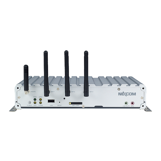
Page 20: Physical Features
VTC 6100. antenna mounting holes Normal PC Mode 3. Mode C. When there is power input, you can turn on VTC 6100 only by pressing the power button. Ignition signal will not power on/off VTC 6100. 4. Mode D. When there is power input, VTC 6100 will turn on automati- cally. - Page 21 WLAN/HSDPA Status SIM Card Socket VTC 6100 can be internally integrated with a 3.5G Mini Card module. The SIM card bracket is on the carrier board. When using the GPRS/UMTS/HS- DPA function, insert the SIM card into the SIM card socket. Make sure to turn off VTC 6100 before inserting the SIM card.
-
Page 22: Rear Panel
Connector pin definition (CN1) Pin No. Function Description DC IN 6V-36V GPIO DVI-D 5V/12V/SMBUS VIN(6V~36V) IGNITION MIC-IN ** Use power cable (+) with fuse for system protection LINE-OUT Copyright © 2009 NEXCOM International Co., Ltd. All Rights Reserved. VTC 6100 User Manual... - Page 23 Connector pin definition Definition Definition DCD (RS232) RXD (RS232) TX-/RX- (RS485) TX+/RX+ (RS485) TXD (RS232) DTR (RS232) DSR (RS232 ) RTS (RS232) CTS (RS232) RI (RS232) Copyright © 2009 NEXCOM International Co., Ltd. All Rights Reserved. VTC 6100 User Manual...
- Page 24 +5 VDC (0.5A) and +12VDC (0.5A) power output and SMBus (w/ VTK 33M-01 connection) LCDD_GND LCDD_GND LCDD07(CLK) LCDD03(OUT1) LCDD06(CLK#) LCDD02(OUT1#) LVDS_GND LCDD_GND LCDD05(OUT2) Power on push button LCDD04(OUT2#) Panel_backlight LCDD_GND Panel-Gnd USB_0# Contact_DET# USB_0 USB_VCC Copyright © 2009 NEXCOM International Co., Ltd. All Rights Reserved. VTC 6100 User Manual...
- Page 25 Audio Jacks (MIC-IN and LINE-OUT) • MIC-IN jack receives monophonic input from an external microphone. • LINE-OUT jack is the stereo output for connecting external speakers. Copyright © 2009 NEXCOM International Co., Ltd. All Rights Reserved. VTC 6100 User Manual...
-
Page 26: Mechanical Dimensions
Chapter 1: Product Introduction Mechanical Dimensions 260.0 176.0 Copyright © 2009 NEXCOM International Co., Ltd. All Rights Reserved. VTC 6100 User Manual... -
Page 27: Chapter 2: Jumpers And Connectors
This chapter describes how to set the jumpers on the motherboard. Note tronic components. Humid environment tend to have less static electric- that the following procedures are generic for all VTC 6100 series. ity than dry environments. A grounding strap is warranted whenever danger of static electricity exists. -
Page 28: Jumper
(on) and open (off). Two-Pin Jumpers: Open (Left) and Short (Right) Three-Pin Jumpers: Pins 1 and 2 Are Short Copyright © 2009 NEXCOM International Co., Ltd. All Rights Reserved. VTC 6100 User Manual... -
Page 29: Locations Of The Jumpers And Connectors
VTC 6100 system. It shows the loca- tions of the jumpers and connectors. CN17 Blue Tooth 3.5G CN16 WLAN CN12 COM1 CON1 LAN1 USB2 CN11 Copyright © 2009 NEXCOM International Co., Ltd. All Rights Reserved. VTC 6100 User Manual... -
Page 30: Jumper Settings
CF (IDE0) Primary Master/Slave Select (JP4) DC Input Voltage Select (JP1) Status Function Description Status Function Description Short Slave 1-2 (default) Short (default) IGNITION 2-3 (default) Short (default) Master Short VIN_M Copyright © 2009 NEXCOM International Co., Ltd. All Rights Reserved. VTC 6100 User Manual... -
Page 31: Temp Sensor (Jp8)
MCU COM Port (JP3) PCI-104 VI/O Select Voltage (J13) Function Description Status Function Description 1-4(*) Short* +3.3V Short MCU Download (JP6) Function Description +V3.3ALW MRST C2CK Copyright © 2009 NEXCOM International Co., Ltd. All Rights Reserved. VTC 6100 User Manual... -
Page 32: Connectors
GBE0_MDI2+ LPC_AD3 AC_SDOUT I2C_CK PCIE0_CK_REF+ RSVD GBE0_LINK# GPI1 GPO3 I2C_DAT PCIE0_CK_REF- GBE0_MDI1- THRM# GBE0_MDI1+ LPC_CLK USB6- RSVD USB6+ RSVD GBE0_MDI0- PWRBTN# USB_6_7_OC# USB_4_5_OC# USB4- USB5- RSVD Copyright © 2009 NEXCOM International Co., Ltd. All Rights Reserved. VTC 6100 User Manual... - Page 33 VCC_12V B104 VCC_12V CB_RESET# A105 VCC_12V B105 VCC_12V A106 VCC_12V B106 VCC_12V A107 VCC_12V B107 VCC_12V A108 VCC_12V B108 VCC_12V A109 VCC_12V B109 VCC_12V A110 B110 Copyright © 2009 NEXCOM International Co., Ltd. All Rights Reserved. VTC 6100 User Manual...
-
Page 34: Com Express Row C And Row D
IDE_D0 SDVO_CLK- PCI_AD14 PCI_PAR IDE_D2 IDE_REQ PCI_C/BE1# PCI_SERR# IDE_D13 IDE_IOW# PCI_PERR# PCI_STOP# IDE_D1 IDE_ACK# PCI_LOCK# PCI_TRDY# PCI_DEVSEL# PCI_FRAME# IDE_D14 IDE_IRQ PCI_IRDY# PCI_AD16 PCI_C/BE2# PCI_AD18 PCI_AD17 PCI_AD20 Copyright © 2009 NEXCOM International Co., Ltd. All Rights Reserved. VTC 6100 User Manual... - Page 35 C106 VCC_12V D106 VCC_12V PEG_RX0+ PEG_TX0+ C107 VCC_12V D107 VCC_12V PEG_RX0- PEG_TX0- C108 VCC_12V D108 VCC_12V TYPE0# PEG_LANE_RV# C109 VCC_12V D109 VCC_12V PEG_RX1+ PEG_TX1+ C110 D110 Copyright © 2009 NEXCOM International Co., Ltd. All Rights Reserved. VTC 6100 User Manual...
-
Page 36: Compactflash Connector
Data 3 Data 10 Data 4 Data 5 Data 6 Data 7 HDC CS100 Disk Address 2 Disk Address 1 Disk Address 0 Data 0 Data 1 Copyright © 2009 NEXCOM International Co., Ltd. All Rights Reserved. VTC 6100 User Manual... -
Page 37: Gpio Connector
Connector location: COM1 (CN9), COM2 (CN7) CN10 BOX-2.0mm-M-180 Connector Pin Definition Connector Pin Definition Definition Definition Description Description GIN1 GIN2 GIN3 GIN4 GOUT4 GOUT1 GOUT2 GOUT3 Copyright © 2009 NEXCOM International Co., Ltd. All Rights Reserved. VTC 6100 User Manual... -
Page 38: Rs232/485 Connector: Com3
Connector Pin Definition Definition Definition Definition Definition DCD (RS232) RXD (RS232) +3.3V TX-/RX- (RS485) TX+/RX+ (RS485) TXD (RS232) DTR (RS232) DSR (RS232) RTS (RS232) CTS (RS232) RI (RS232) Copyright © 2009 NEXCOM International Co., Ltd. All Rights Reserved. VTC 6100 User Manual... -
Page 39: Mcu Programmer Pin Header
Connector location: JP6 Connector location: CON1 PIN-2.54mm-M-180 Connector Pin Definition Connector Pin Definition Definition Definition GREEN Definition Definition BLUE +3.3ALW MRST C2CK DDCDAT Hsync Vsync DDCCLK Copyright © 2009 NEXCOM International Co., Ltd. All Rights Reserved. VTC 6100 User Manual... -
Page 40: Lvds Connector + Usb0
USB_VCC (+5V) USB_GND USB_GND Panel_backlight(+12V) BOX-2.0mm-M-180 Connector Pin Definition Definition Definition LVDS_CLK LVDS_DAT Panel_VDD LVDS_1(OUT0) LVDS_9(OUT3) LVDS_0(OUT0#) LVDS_8(OUT3#) Panel_VDD LVDS_GND LVDS_GND LVDS_7(CLK) LVDS_3(OUT1) LVDS_6(CLK#) LVDS_2(OUT1#) LVDS_GND LVDS_GND Copyright © 2009 NEXCOM International Co., Ltd. All Rights Reserved. VTC 6100 User Manual... -
Page 41: Lan Connector
Connector location: LAN1 Connector Pin Definition Connector Pin Definition Definition Definition Definition Definition DATA- DATA+ N/C1 N/C2 N/C3 N/C4 LAN Speed LED +3.3V LAN Link LED +3.3V Copyright © 2009 NEXCOM International Co., Ltd. All Rights Reserved. VTC 6100 User Manual... -
Page 42: Usb Connector Usb 2
LVDS Power Connector Connector location: USB2 Connector location: J5 Connector Pin Definition Definition Definition Panel_backlight Panel_VDD Connector Pin Definition Definition Definition LVDS_PANEL LVDS_BIASON DATA1- DATA1+ DATA- DATA+ Copyright © 2009 NEXCOM International Co., Ltd. All Rights Reserved. VTC 6100 User Manual... -
Page 43: External 12V & 5V Power And Smbus Connector
External 12V & 5V Power and SMBUS Connector Mic-in Connector location: CN2 Connector location: CN11 and CN15 Connector Pin Definition Connector Pin Definition Definition Definition Definition Definition MIC_JD MIC_OUT SMBCLK SMBDATA Copyright © 2009 NEXCOM International Co., Ltd. All Rights Reserved. VTC 6100 User Manual... -
Page 44: Line-Out
Connector location: J13 Connector Pin Definition Definition Definition Connector Pin Definition LINE_OUT_L SURR_JD Pin No. Status Function Description LINE_OUT_R 1-3, 2-4 (default) Short +3.3V 3-5, 4-6 Short Copyright © 2009 NEXCOM International Co., Ltd. All Rights Reserved. VTC 6100 User Manual... -
Page 45: Pci-104 Connector
Chapter 2: Jumpers and Connectors PCI-104 Connector Power Button Connector location: CN16 Connector location: SW1 Connector Pin Definition Reset Button Connector location: SW2 Copyright © 2009 NEXCOM International Co., Ltd. All Rights Reserved. VTC 6100 User Manual... -
Page 46: Mcu Com Port
Chapter 2: Jumpers and Connectors MCU COM Port ACC_ON LED Connector location: JP3 Connector location: JP7 Connector Pin Definition Function Description Connector Pin Definition Function Description +3.3V LED Copyright © 2009 NEXCOM International Co., Ltd. All Rights Reserved. VTC 6100 User Manual... -
Page 47: Temp Sensor
Temp Sensor DC Power Input Connector Connector location: JP8 Connector location: CN1 Connector Pin Definition Connector Pin Definition Function Description SENSOR+ Function Description VIN (6V~36V) IGNITION Copyright © 2009 NEXCOM International Co., Ltd. All Rights Reserved. VTC 6100 User Manual... -
Page 48: Power On And Ide Active Led
LED I/O Port Address and Data Connector Pin Definition Function Description Function Description POWER LED I/O PORT Address: 0EE0; Bit0: 1 (Light), 0 (Dark) HD LED UMTS STATUS Copyright © 2009 NEXCOM International Co., Ltd. All Rights Reserved. VTC 6100 User Manual... -
Page 49: Serial Ata
Serial ATA Power Input Connector location: CN6 Connector location: J10 Connector Pin Definition Connector Pin Definition Definition Definition Definition Definition +V12S SATA_TXP0 - +V5S SATA_TXN0 SATA_RXN0 SATA_RXP0 Copyright © 2009 NEXCOM International Co., Ltd. All Rights Reserved. VTC 6100 User Manual... -
Page 50: Mini-Pcie Socket (For 3.5G Module) Pcie Interface
REFCLK- USB_D+ MSM26_ REFCLK+ USIM RST +V3.3S LED_ WWAN# +V3.3S LED_ WWAN# LED_ WLAN# DISABLE# LED_ W_DIS- WPAN# ABLE# PERST# +V1.5S PERn0 +3.3S PERp0 +V3.3S +V3.3S Copyright © 2009 NEXCOM International Co., Ltd. All Rights Reserved. VTC 6100 User Manual... -
Page 51: Sim Card Connector
Connector location: J7 JST-1mm-M-90 Definition Definition Connector Pin Definition USB_6P_L USB_6N_L Definition Definition BT_AUDIO_EN_R POWER VOLTAGE RESET SIGNAL BT_3.3V CLOCK SIGNAL VPP:PROGRAM VOLTAGE Contact present switch Copyright © 2009 NEXCOM International Co., Ltd. All Rights Reserved. VTC 6100 User Manual... -
Page 52: Chapter 3: System Setup
Remove these screws and put them in a safe place for later use. Bottom View 2. Lift the cover upward then remove it from the chassis. Front View Rear View Copyright © 2009 NEXCOM International Co., Ltd. All Rights Reserved. VTC 6100 User Manual... -
Page 53: Installing A Gprs/Umts/Hsdpa Module
1. The Mini PCI Express slot shown below is used to install a 3.5G com- disappears inside the slot. munication module such as GPRS, UMTS or HSDPA module. GPRS/UMTS/ HSDPA module Mini PCI Express slot Mini PCI Express slot Copyright © 2009 NEXCOM International Co., Ltd. All Rights Reserved. VTC 6100 User Manual... - Page 54 3. Push the module down then secure it with mounting screws. 4. Attach one end of the RF cable onto the module. Attach RF cable to the module Copyright © 2009 NEXCOM International Co., Ltd. All Rights Reserved. VTC 6100 User Manual...
- Page 55 6. Mount the other end of the cable to the antenna mounting hole lo- onto the module. cated at the front panel of the chassis. RF cable mounted at the front panel Copyright © 2009 NEXCOM International Co., Ltd. All Rights Reserved. VTC 6100 User Manual...
-
Page 56: Installing A Wireless Lan Module
1. The Mini PCI Express slot shown below is used to install a wireless LAN ule completely disappears inside the slot. module. Wireless LAN module Mini PCI Express slot Mini PCI Express slot Copyright © 2009 NEXCOM International Co., Ltd. All Rights Reserved. VTC 6100 User Manual... - Page 57 3. Push the module down then secure it with mounting screws. 4. Attach one end of the RF cable onto the module. Attach RF cable to the module Copyright © 2009 NEXCOM International Co., Ltd. All Rights Reserved. VTC 6100 User Manual...
- Page 58 6. Mount the other end of the cable to the antenna mounting hole lo- onto the module. cated at the front panel of the chassis. RF cable mounted at the front panel Copyright © 2009 NEXCOM International Co., Ltd. All Rights Reserved. VTC 6100 User Manual...
-
Page 59: Installing A Bluetooth Module
2. Install the provided mounting stud as shown in the illustration below. 1. The USB header shown below is used to install a Bluetooth module. Mounting stud header Copyright © 2009 NEXCOM International Co., Ltd. All Rights Reserved. VTC 6100 User Manual... - Page 60 5. Mount the other end of the cable to the Bluetooth mounting hole located at the front panel of the chassis. Bluetooth module Cable connector Copyright © 2009 NEXCOM International Co., Ltd. All Rights Reserved. VTC 6100 User Manual...
-
Page 61: Installing A Compactflash Card
2. With the CompactFlash card’s label facing up, position the card to the socket. 1. Locate for the CompactFlash socket on the board. CompactFlash CompactFlash card socket Copyright © 2009 NEXCOM International Co., Ltd. All Rights Reserved. VTC 6100 User Manual... - Page 62 Chapter 3: System Setup 3. Insert the card until it is completely seated in the socket. Copyright © 2009 NEXCOM International Co., Ltd. All Rights Reserved. VTC 6100 User Manual...
-
Page 63: Installing The Pci-104 Module
1. Locate for the PCI-104 slot on the board. the module’s mounting holes to the mounting studs on the board. PCI-104 module Mounting hole PCI-104 slot Mounting stud Mounting stud Copyright © 2009 NEXCOM International Co., Ltd. All Rights Reserved. VTC 6100 User Manual... - Page 64 Chapter 3: System Setup 3. Secure the module with mounting screws. Copyright © 2009 NEXCOM International Co., Ltd. All Rights Reserved. VTC 6100 User Manual...
-
Page 65: Installing A Sata Hard Drive
Refer to their respective sections in this chapter for in- structions on installing a CF card or a Mini PCI Express module. Mounting screws Copyright © 2009 NEXCOM International Co., Ltd. All Rights Reserved. VTC 6100 User Manual... - Page 66 Head bolt screw HDD bracket HDD bracket Metal bracket Screwdriver Top View HDD bracket HDD bracket Screwdriver Bottom View Copyright © 2009 NEXCOM International Co., Ltd. All Rights Reserved. VTC 6100 User Manual...
- Page 67 6. Locate for the SATA connector and the power connector. on the board. Tighten the head bolt screws to secure the drive to the chassis. Mounting stud Power connector SATA connector Head bolt screw Copyright © 2009 NEXCOM International Co., Ltd. All Rights Reserved. VTC 6100 User Manual...
-
Page 68: Iceb 6000 I/O Address Function
SATA power connector Cable connected to on the board Cable connected Cable connected the SATA connector to the SATA drive to the SATA drive on the board Copyright © 2009 NEXCOM International Co., Ltd. All Rights Reserved. VTC 6100 User Manual... -
Page 69: Installing The Sodimm
The gold-plated connector on the edge of the module Remove the heatspreader’s mounting screws. will almost completely disappear inside the socket. Heatspreader SODIMM socket SODIMM Copyright © 2009 NEXCOM International Co., Ltd. All Rights Reserved. VTC 6100 User Manual... - Page 70 3. Push the module down until the clips on both sides of the socket lock into position. You will hear a distinctive “click”, indicating the module is correctly locked into position. Clip Copyright © 2009 NEXCOM International Co., Ltd. All Rights Reserved. VTC 6100 User Manual...
-
Page 71: Installing The Usb Cable Holder
The USB cable holder is used to stabilize the USB cable so as to prevent it from getting loose when accidentally pulled or moved. 1. Attach the cable holder to the mounting hole by using the provided screw. Cable holder Copyright © 2009 NEXCOM International Co., Ltd. All Rights Reserved. VTC 6100 User Manual... -
Page 72: Rackmount Brackets
Fasten screws to Secure the mount the system bracket to to the wall the system Rackmount bracket Copyright © 2009 NEXCOM International Co., Ltd. All Rights Reserved. VTC 6100 User Manual... -
Page 73: I/O Address Function
Bit 2 Ignition (read only) 0: OFF 1: ON Bit 3 Status of Vehicle Battery 0: Vehicle Battery is OK 1: Vehicle Battery is Low Voltage Copyright © 2009 NEXCOM International Co., Ltd. All Rights Reserved. VTC 6100 User Manual... - Page 74 Status of Fan R 0: Action 1: Inaction Bit 6 Status of Fan L 0: Well 1: Failed Bit 7 Status of Fan L 0: Action 1: Inaction Copyright © 2009 NEXCOM International Co., Ltd. All Rights Reserved. VTC 6100 User Manual...
- Page 75 External +12V power 0: Disable 1: Enable (default) Bit 3 External +5V power 0: Disable 1: Enable (default) Auto clear WDT timer when reading/writing I/O port 0EE5H. Copyright © 2009 NEXCOM International Co., Ltd. All Rights Reserved. VTC 6100 User Manual...
-
Page 76: Appendix B: Ices 270 Com Express Cpu Module
- Drive a standard progressive scan analog monitor with pixel resolution • DDR2 400/533 SO-DIMM up to 1600x1200 @ 85 Hz, 2048x1536 @60Hz • 10/100/1000 Ethernet controller • LVDS/SDVO interface Copyright © 2009 NEXCOM International Co., Ltd. All Rights Reserved. VTC 6100 User Manual... - Page 77 Supports Suspend to RAM (S3) • PATA PCI/PCIe • 32-bit PCI V2.3 interface • PCI express x 1 - 5 Lanes (via dip switch for 5x1 or 1x1+ 1x4) Copyright © 2009 NEXCOM International Co., Ltd. All Rights Reserved. VTC 6100 User Manual...
- Page 78 Environment • Operating temperature: -20°C ~ 60°C • Storage temperature: -20°C ~ 85°C • Relative humidity: 10% to 90% (operating, non-condensing) 5% to 95% (non-operating, non-condensing) Copyright © 2009 NEXCOM International Co., Ltd. All Rights Reserved. VTC 6100 User Manual...
-
Page 79: Mechanical Dimensions
Appendix B: ICES 270 COM Express CPU Module Mechanical Dimensions Copyright © 2009 NEXCOM International Co., Ltd. All Rights Reserved. VTC 6100 User Manual... -
Page 80: Pci Routing
AD22 AD23 INTA# IRQA IRQB IRQC IRQD INTB# IRQB IRQC IRQD IRQA INTC# IRQC IRQD IRQA IRQB INTD# IRQD IRQA IRQB IRQC COM Express Module Connector Copyright © 2009 NEXCOM International Co., Ltd. All Rights Reserved. VTC 6100 User Manual... -
Page 81: Connectors
THRM# GBE0_MDI1+ LPC_CLK PCIE_TX1- PCIE_RX1- USB6- USB7- RSVD VGA_GRN WAKE0# USB6+ USB7+ RSVD VGA_BLU GBE0_MDI0- PWRBTN# GPI2 WAKE1# USB_6_7_OC# USB_4_5_OC# GPO0 VGA_HSYNC USB4- USB5- RSVD VGA_VSYNC Copyright © 2009 NEXCOM International Co., Ltd. All Rights Reserved. VTC 6100 User Manual... - Page 82 A105 VCC_12V B105 VCC_12V A106 VCC_12V B106 VCC_12V A107 VCC_12V B107 VCC_12V A108 VCC_12V B108 VCC_12V GPI0 GPO1 A109 VCC_12V B109 VCC_12V PCIE_TX4+ PCIE_RX4+ A110 B110 Copyright © 2009 NEXCOM International Co., Ltd. All Rights Reserved. VTC 6100 User Manual...
- Page 83 PEG_TX11- IDE_D1 IDE_ACK# PEG_RX4+ PEG_TX4+ PCI_LOCK# PCI_TRDY# PEG_RX4- PEG_TX4- PCI_DEVSEL# PCI_FRAME# PEG_RX12+ PEG_TX12+ IDE_D14 IDE_IRQ RSVD PCI_IRDY# PCI_AD16 PEG_RX12- PEG_TX12- PCI_C/BE2# PCI_AD18 PCI_AD17 PCI_AD20 PEG_RX13+ PEG_TX13+ Copyright © 2009 NEXCOM International Co., Ltd. All Rights Reserved. VTC 6100 User Manual...
- Page 84 VCC_12V C106 VCC_12V D106 VCC_12V PEG_RX0+ SDVOB_RED+ C107 VCC_12V D107 VCC_12V PEG_RX0- SDVOB_RED- C108 VCC_12V D108 VCC_12V PEG_LANE_RV# C109 VCC_12V D109 VCC_12V SDVOB_ C110 D110 GREEN+ Copyright © 2009 NEXCOM International Co., Ltd. All Rights Reserved. VTC 6100 User Manual...
- Page 85 Connector size: 1 x 3 = 3 Pins Connector location: FAN1 FAN1 SW_DIP-2 Status Config WAFER-2.54mm-M-180 1 and 2 PCIE 4X1 Definition 1 and 2 PCIE 1X4 +12V FAN_SENSOR Copyright © 2009 NEXCOM International Co., Ltd. All Rights Reserved. VTC 6100 User Manual...
-
Page 86: Appendix C: Iceb 6100 Carrier Board
1 reset switch • 1 SIM card socket • 1 USB 2.0 • 4 LEDs for Standby, HDD, WLAN/HSDPA and GPO • 1 line-out • 1 mic-in Copyright © 2009 NEXCOM International Co., Ltd. All Rights Reserved. VTC 6100 User Manual... -
Page 87: Jumpers And Connectors
Appendix C: ICEB 6100 Carrier Board Jumpers and Connectors LED1 CN15 CN14 LED2 USB1 CN17 Blue Tooth 3.5G CN16 WLAN CN12 COM1 CON1 LAN1 USB2 CN11 Copyright © 2009 NEXCOM International Co., Ltd. All Rights Reserved. VTC 6100 User Manual... - Page 88 CF (IDE0) Primary Master/Slave Select (JP4) DC Input Voltage Select (JP1) Status Function Description Status Function Description Short Slave 1-2 (default) Short (default) IGNITION 2-3 (default) Short (default) Master Short VIN_M Copyright © 2009 NEXCOM International Co., Ltd. All Rights Reserved. VTC 6100 User Manual...
- Page 89 MCU COM Port (JP3) PCI-104 VI/O Select Voltage (J13) Function Description Status Function Description 1-4(*) Short* +3.3V Short MCU Download (JP6) Function Description +V3.3ALW MRST C2CK Copyright © 2009 NEXCOM International Co., Ltd. All Rights Reserved. VTC 6100 User Manual...
- Page 90 GBE0_MDI2+ LPC_AD3 AC_SDOUT I2C_CK PCIE0_CK_REF+ RSVD GBE0_LINK# GPI1 GPO3 I2C_DAT PCIE0_CK_REF- GBE0_MDI1- THRM# GBE0_MDI1+ LPC_CLK USB6- RSVD USB6+ RSVD GBE0_MDI0- PWRBTN# USB_6_7_OC# USB_4_5_OC# USB4- USB5- RSVD Copyright © 2009 NEXCOM International Co., Ltd. All Rights Reserved. VTC 6100 User Manual...
- Page 91 VCC_12V B104 VCC_12V CB_RESET# A105 VCC_12V B105 VCC_12V A106 VCC_12V B106 VCC_12V A107 VCC_12V B107 VCC_12V A108 VCC_12V B108 VCC_12V A109 VCC_12V B109 VCC_12V A110 B110 Copyright © 2009 NEXCOM International Co., Ltd. All Rights Reserved. VTC 6100 User Manual...
- Page 92 IDE_D0 SDVO_CLK- PCI_AD14 PCI_PAR IDE_D2 IDE_REQ PCI_C/BE1# PCI_SERR# IDE_D13 IDE_IOW# PCI_PERR# PCI_STOP# IDE_D1 IDE_ACK# PCI_LOCK# PCI_TRDY# PCI_DEVSEL# PCI_FRAME# IDE_D14 IDE_IRQ PCI_IRDY# PCI_AD16 PCI_C/BE2# PCI_AD18 PCI_AD17 PCI_AD20 Copyright © 2009 NEXCOM International Co., Ltd. All Rights Reserved. VTC 6100 User Manual...
- Page 93 C106 VCC_12V D106 VCC_12V PEG_RX0+ PEG_TX0+ C107 VCC_12V D107 VCC_12V PEG_RX0- PEG_TX0- C108 VCC_12V D108 VCC_12V TYPE0# PEG_LANE_RV# C109 VCC_12V D109 VCC_12V PEG_RX1+ PEG_TX1+ C110 D110 Copyright © 2009 NEXCOM International Co., Ltd. All Rights Reserved. VTC 6100 User Manual...
- Page 94 Data 3 Data 10 Data 4 Data 5 Data 6 Data 7 HDC CS100 Disk Address 2 Disk Address 1 Disk Address 0 Data 0 Data 1 Copyright © 2009 NEXCOM International Co., Ltd. All Rights Reserved. VTC 6100 User Manual...
- Page 95 Connector location: COM1 (CN9), COM2 (CN7) CN10 BOX-2.0mm-M-180 Connector Pin Definition Connector Pin Definition Definition Definition Description Description GIN1 GIN2 GIN3 GIN4 GOUT4 GOUT1 GOUT2 GOUT3 Copyright © 2009 NEXCOM International Co., Ltd. All Rights Reserved. VTC 6100 User Manual...
- Page 96 Connector Pin Definition Definition Definition Definition Definition DCD (RS232) RXD (RS232) +3.3V TX-/RX- (RS485) TX+/RX+ (RS485) TXD (RS232) DTR (RS232) DSR (RS232) RTS (RS232) CTS (RS232) RI (RS232) Copyright © 2009 NEXCOM International Co., Ltd. All Rights Reserved. VTC 6100 User Manual...
- Page 97 Connector location: JP6 Connector location: CON1 PIN-2.54mm-M-180 Connector Pin Definition Connector Pin Definition Definition Definition GREEN Definition Definition BLUE +3.3ALW MRST C2CK DDCDAT Hsync Vsync DDCCLK Copyright © 2009 NEXCOM International Co., Ltd. All Rights Reserved. VTC 6100 User Manual...
- Page 98 USB_VCC (+5V) USB_GND USB_GND Panel_backlight(+12V) BOX-2.0mm-M-180 Connector Pin Definition Definition Definition LVDS_CLK LVDS_DAT Panel_VDD LVDS_1(OUT0) LVDS_9(OUT3) LVDS_0(OUT0#) LVDS_8(OUT3#) Panel_VDD LVDS_GND LVDS_GND LVDS_7(CLK) LVDS_3(OUT1) LVDS_6(CLK#) LVDS_2(OUT1#) LVDS_GND LVDS_GND Copyright © 2009 NEXCOM International Co., Ltd. All Rights Reserved. VTC 6100 User Manual...
- Page 99 Connector location: LAN1 Connector Pin Definition Connector Pin Definition Definition Definition Definition Definition DATA- DATA+ N/C1 N/C2 N/C3 N/C4 LAN Speed LED +3.3V LAN Link LED +3.3V Copyright © 2009 NEXCOM International Co., Ltd. All Rights Reserved. VTC 6100 User Manual...
- Page 100 LVDS Power Connector Connector location: USB2 Connector location: J5 Connector Pin Definition Definition Definition Panel_backlight Panel_VDD Connector Pin Definition Definition Definition LVDS_PANEL LVDS_BIASON DATA1- DATA1+ DATA- DATA+ Copyright © 2009 NEXCOM International Co., Ltd. All Rights Reserved. VTC 6100 User Manual...
- Page 101 External 12V & 5V Power and SMBUS Connector Mic-in Connector location: CN2 Connector location: CN11 and CN15 Connector Pin Definition Connector Pin Definition Definition Definition Definition Definition MIC_JD MIC_OUT SMBCLK SMBDATA Copyright © 2009 NEXCOM International Co., Ltd. All Rights Reserved. VTC 6100 User Manual...
- Page 102 Connector location: J13 Connector Pin Definition Definition Definition Connector Pin Definition LINE_OUT_L SURR_JD Pin No. Status Function Description LINE_OUT_R 1-3, 2-4 (default) Short +3.3V 3-5, 4-6 Short Copyright © 2009 NEXCOM International Co., Ltd. All Rights Reserved. VTC 6100 User Manual...
- Page 103 Appendix C: ICEB 6100 Carrier Board PCI-104 Connector Power Button Connector location: CN16 Connector location: SW1 Connector Pin Definition Reset Button Connector location: SW2 Copyright © 2009 NEXCOM International Co., Ltd. All Rights Reserved. VTC 6100 User Manual...
- Page 104 Appendix C: ICEB 6100 Carrier Board MCU COM Port ACC_ON LED Connector location: JP3 Connector location: JP7 Connector Pin Definition Function Description Connector Pin Definition Function Description +3.3V LED Copyright © 2009 NEXCOM International Co., Ltd. All Rights Reserved. VTC 6100 User Manual...
- Page 105 Temp Sensor DC Power Input Connector Connector location: JP8 Connector location: CN1 Connector Pin Definition Connector Pin Definition Function Description SENSOR+ Function Description VIN (6V~36V) IGNITION Copyright © 2009 NEXCOM International Co., Ltd. All Rights Reserved. VTC 6100 User Manual...
- Page 106 LED I/O Port Address and Data Connector Pin Definition Function Description Function Description POWER LED I/O PORT Address: 0EE0; Bit0: 1 (Light), 0 (Dark) HD LED UMTS STATUS Copyright © 2009 NEXCOM International Co., Ltd. All Rights Reserved. VTC 6100 User Manual...
- Page 107 Serial ATA Power Input Connector location: CN6 Connector location: J10 Connector Pin Definition Connector Pin Definition Definition Definition Definition Definition +V12S SATA_TXP0 - +V5S SATA_TXN0 SATA_RXN0 SATA_RXP0 Copyright © 2009 NEXCOM International Co., Ltd. All Rights Reserved. VTC 6100 User Manual...
- Page 108 REFCLK- USB_D+ MSM26_ REFCLK+ USIM RST +V3.3S LED_ WWAN# +V3.3S LED_ WWAN# LED_ WLAN# DISABLE# LED_ W_DIS- WPAN# ABLE# PERST# +V1.5S PERn0 +3.3S PERp0 +V3.3S +V3.3S Copyright © 2009 NEXCOM International Co., Ltd. All Rights Reserved. VTC 6100 User Manual...
- Page 109 Connector location: J7 JST-1mm-M-90 Definition Definition Connector Pin Definition USB_6P_L USB_6N_L Definition Definition BT_AUDIO_EN_R POWER VOLTAGE RESET SIGNAL BT_3.3V CLOCK SIGNAL VPP:PROGRAM VOLTAGE Contact present switch Copyright © 2009 NEXCOM International Co., Ltd. All Rights Reserved. VTC 6100 User Manual...
-
Page 110: Appendix D: Vehicle Power Management Setup
Appendix D: BIOS Setup d: V ppendix ehicle ower AnAgeMent etup External Power Output Setting External +12V and +5V Turn Off Simultaneously External +12V and +5V Turn On Simultaneously Copyright © 2009 NEXCOM International Co., Ltd. All Rights Reserved. VTC 6100 User Manual... - Page 111 Appendix D: BIOS Setup External +12V Turn On Only External +5V Turn On Only Copyright © 2009 NEXCOM International Co., Ltd. All Rights Reserved. VTC 6100 User Manual...
- Page 112 If the input voltage setting is 6V~36V, ignore the startup/shutdown set- shutdown voltage to 21V. ting. If the input voltage setting is 6V~36V, ignore the startup/shutdown set- ting. Copyright © 2009 NEXCOM International Co., Ltd. All Rights Reserved. VTC 6100 User Manual...
- Page 113 23V. If the input voltage setting is 6V~36V, ignore the startup/shutdown set- If the input voltage setting is 6V~36V ignore the startup/shutdown set- ting. ting. Copyright © 2009 NEXCOM International Co., Ltd. All Rights Reserved. VTC 6100 User Manual...
- Page 114 Appendix D: BIOS Setup Power-on Delay Setting Enable Power-on Delay Delay time can be set at 10sec/30sec/1min./5min./10min./15min./30min./ Disable Power-on Delay 1hour. Copyright © 2009 NEXCOM International Co., Ltd. All Rights Reserved. VTC 6100 User Manual...
- Page 115 Appendix D: BIOS Setup Power-off Delay Setting Disable Power-off Delay Copyright © 2009 NEXCOM International Co., Ltd. All Rights Reserved. VTC 6100 User Manual...
- Page 116 Appendix D: BIOS Setup Enable Power-off Delay Delay time can be set at 20sec/1min./5min./10min./30min./1hour/6hour/ 18hour. Copyright © 2009 NEXCOM International Co., Ltd. All Rights Reserved. VTC 6100 User Manual...
-
Page 117: Appendix E: Power Consumption
Idle Mode 100% Burn-in Mode 1.11A / 12V 1.32A / 12V 0.8A / 12V 0.1A /12V * Device: 80GB HDD, 1GB memory, mouse, keyboard, VGA monitor Copyright © 2009 NEXCOM International Co., Ltd. All Rights Reserved. VTC 6100 User Manual...
Need help?
Do you have a question about the VTC 6100 and is the answer not in the manual?
Questions and answers