
Related Manuals for Nexcom VTC 7260


Summary of Contents for Nexcom VTC 7260
- Page 1 NEXCOM International Co., Ltd. Mobile Computing Solutions Vehicle Telematics Computer VTC 7260 User Manual NEXCOM International Co., Ltd. www.nexcom.com Published July 2022...
-
Page 2: Table Of Contents
RS232 Connector (VTC 7260-x non-PoE Version) .......21 VTC 7260-x LED Description ..............4 GbE/Mgt. Connector .................22 VTC 7260-xC4 Overview .................5 Key Features ...................6 Hardware Specifications ................6 Copyright © 2022 NEXCOM International Co., Ltd. All Rights Reserved. VTC 7260 Series User Manual... - Page 3 M.2 2230 E-Key Connector (PCIe3.0 x2 + USB2.0 interface) for Wi-Fi Module or Hailo AI Card ..........33 Appendix C: GPS Feature Locations of the Jumpers and Connectors for the VTC 7260 ....34 uBlox-NEO M8 Overview ...............58 Bottom View ..................34 Technical Specifications .................58 Internal Connectors ................35...
- Page 4 BIOS Screen with TPM Module ..............75 BIOS Screen with No TPM Module ............75 Appendix H: Power Consumption ......76 Appendix I: Cable Information Multi-port DB15 External Cable.............78 Copyright © 2022 NEXCOM International Co., Ltd. All Rights Reserved. VTC 7260 Series User Manual...
-
Page 5: Preface
Acknowledgements The product(s) described in this manual complies with all applicable VTC 7260 are trademarks of NEXCOM International Co., Ltd. All other European Union (CE) directives if it has a CE marking. For computer systems product names mentioned herein are registered trademarks of their to remain CE compliant, only CE-compliant parts may be used. -
Page 6: Rohs Compliance
0.1% or 1,000ppm, and Polybrominated diphenyl Ethers (PBDE) < 0.1% or 1,000ppm. In order to meet the RoHS compliant directives, NEXCOM has established an engineering and manufacturing task force in to implement the introduction of green products. The task force will ensure that we follow the standard... -
Page 7: Warranty And Rma
▪ Replace with 3rd party products if needed. encountered and note anything abnormal or, print out any on-screen ▪ If RMA goods can not be repaired, NEXCOM will return it to the customer messages, and describe the problems on the “NEXCOM RMA Service without any charge. - Page 8 Always power off the system before inserting or removing the SIM only with the same or equivalent type recommended by the manufacturer. card. Discard used batteries according to the manufacturer’s instructions. viii Copyright © 2022 NEXCOM International Co., Ltd. All Rights Reserved. VTC 7260 Series User Manual...
- Page 9 ACCORDING TO THE MANUFACTURER’S INSTRUCTIONS. rating marked on the product. ▪ All cautions and warnings on the equipment should be noted. Copyright © 2022 NEXCOM International Co., Ltd. All Rights Reserved. VTC 7260 Series User Manual...
-
Page 10: Technical Support And Assistance
Preface Technical Support and Assistance Conventions Used in this Manual 1. For the most updated information of NEXCOM products, visit NEXCOM’s Warning: website at www.nexcom.com. Information about certain situations, which if not observed, can cause personal injury. This will prevent injury to yourself 2. -
Page 11: Global Service Contact Information
Tel: +886-2-8226-7786 Tel: +886-2-8976-3077 Beitun District, Fax: +886-2-8226-7782 Email: sales@diviotec.com Taichung City, 406, Taiwan, R.O.C. Email: services@tmrtek.com www.diviotec.com Tel: +886-4-2249-1179 www.tmrtek.com Fax: +886-4-2249-1172 Email: jacobhuang@nexaiot.com www.nexaiot.com Copyright © 2022 NEXCOM International Co., Ltd. All Rights Reserved. VTC 7260 Series User Manual... - Page 12 LongGang District, 4-11-5, Shiba Minato-ku, ShenZhen, 518112, China Tokyo, 108-0014, Japan Tel: +86-755-8364-7768 Tel: +81-3-5419-7830 Fax: +86-755-8364-7738 Fax: +81-3-5419-7832 Email: steveyang@nexcom.com.tw Email: sales@nexcom-jp.com www.nexcom.cn www.nexcom-jp.com Copyright © 2022 NEXCOM International Co., Ltd. All Rights Reserved. VTC 7260 Series User Manual...
-
Page 13: Package Contents
Preface Package Contents Before continuing, please verify the VTC 7260 package that you received is complete. Your VTC 7260 package should have all the items listed in the following table. Item Name Description 4NCPM00302X00 Terminal Blocks 3P Terminal Blocks 3P Phoenix Contact:1777992 5.08mm Male Dip Green... -
Page 14: Vtc 7260 Product Skus
Preface VTC 7260 Product SKUs There’s two series of VTC 7260. One is the product without PoE function, the other is the product with 4 PoE function built-in. 1. The SKU with PoE function, you can order: - VTC 7260-5C4 (P/N: tbd): Intel® Tiger-lake UP3 Core i5-1145GRE, 4 x 2.5GigE PoE +1 x GbE... -
Page 15: Chapter 1: Product Introduction
Symbol “I” means Ignition that is connected to the car’s IGN. optional I/Os function if needed. To power up the machine, the Ignition (I) must be kept on HIGH-level. Copyright © 2022 NEXCOM International Co., Ltd. All Rights Reserved. VTC 7260 Series User Manual... -
Page 16: Physical Features
Symbol “I” means Ignition that is connected to the car’s IGN. optional I/Os function if needed. To power up the machine, the Ignition (I) must be kept on HIGH-level. Copyright © 2022 NEXCOM International Co., Ltd. All Rights Reserved. VTC 7260 Series User Manual... -
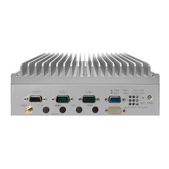
Page 17: Vtc 7260-Xc4 Led Description
▪ Solid green: Power feed to PD node ▪ Off: No power-feed to PD node POE4 POE4-port power indicator ▪ Solid green: Power feed to PD node Copyright © 2022 NEXCOM International Co., Ltd. All Rights Reserved. VTC 7260 Series User Manual... -
Page 18: Vtc 7260-X Led Description
▪ Soild red: A fatal error occurred ▪ Please refer to ATC8110 Commands list at ST_SYSTEM_GET_33_02_ Prog. 1~4 User programmed indicator PROGRAM_LED_STATUS for Linux Copyright © 2022 NEXCOM International Co., Ltd. All Rights Reserved. VTC 7260 Series User Manual... -
Page 19: Vtc 7260-Xc4 Overview
-40°C~70°C and is compliant with MILSTD-810G military standard for anti-vibration/shock. For the regulation, VTC 7260-xC4 is compliant with CE/FCC classA, UKCA and EMARK (E13) Copyright © 2022 NEXCOM International Co., Ltd. All Rights Reserved. -
Page 20: Key Features
Key M 2242/2280 slot on VTC7260. To purchase, please contact supported NEXCOM sales. ▪ 1 x M.2 2230 Key E socket (PCIe 3.0 x2 & USB 2.0), Wi-Fi or Hailo AI card in option Copyright © 2022 NEXCOM International Co., Ltd. All Rights Reserved. VTC 7260 Series User Manual... - Page 21 500mA max (@25C) ▪ 1 x USB 2.0, host type-A connector ▪ Source or external can be selected by DIP switch (default: source type) Copyright © 2022 NEXCOM International Co., Ltd. All Rights Reserved. VTC 7260 Series User Manual...
- Page 22 ▪ Linux (Ubuntu 18.04) Phoenix), 4 x PR-SMA for WLAN External Cable I/O ports, side-plate ▪ DB15 multi-port adapter cable, 20cm ▪ 2 x SIM slots (SIM1-1, SIM2-1) Copyright © 2022 NEXCOM International Co., Ltd. All Rights Reserved. VTC 7260 Series User Manual...
-
Page 23: Vtc 7260-X Overview
Moreover, its 10-year product life-cycle policy can satisfy with the long-term support suitable for any from in-vehicle applications. With the compact, rugged, and fanless design, VTC 7260-x can widely and easily be installed in any limited cabinet space, and reduce the maintenance efforts while operating 24/7 services. -
Page 24: Key Features
Key M 2242/2280 slot on VTC7260. To purchase, please contact supported NEXCOM sales. ▪ 1 x M.2 2230 Key E socket (PCIe 3.0 x2 & USB 2.0), Wi-Fi or Hailo AI card in option Copyright © 2022 NEXCOM International Co., Ltd. All Rights Reserved. VTC 7260 Series User Manual... - Page 25 ▪ Source or external can be selected by DIP switch (default: source type) ▪ 1 x USB 2.0, host type-A connector Serial Port ▪ 2 x full RS232/422/485, selectable Copyright © 2022 NEXCOM International Co., Ltd. All Rights Reserved. VTC 7260 Series User Manual...
- Page 26 ▪ Linux (Ubuntu 18.04) Phoenix), 4 x PR-SMA for WLAN External Cable I/O ports, side-plate ▪ DB15 multi-port adapter cable, 20cm ▪ 2 x SIM slots (SIM1-1, SIM2-1) Copyright © 2022 NEXCOM International Co., Ltd. All Rights Reserved. VTC 7260 Series User Manual...
-
Page 27: Connector Numbering
2 of the manual. VTC 7260 Front View VTC 7260 Rear View Copyright © 2022 NEXCOM International Co., Ltd. All Rights Reserved. VTC 7260 Series User Manual... -
Page 28: Chapter 2: External Connectors Pinout Description
2: e haPter xternal onneCtors Inout esCrIPtIon Power Button Reset Button Connector number: 1 Connector number: 2 Definition Definition Definition HW_BT# HW_BT# RST_BTN# PWRLED_A PWRLED_C Copyright © 2022 NEXCOM International Co., Ltd. All Rights Reserved. VTC 7260 Series User Manual... -
Page 29: Usb 2.0 And Usb 3.2 Port
RS232 DCD#/RS422 TX-/ RS232 RX/RS422 TX+/ RS485 DATA- RS485 DATA+ USB_1P RS232 TX/RS422 RX+ RS232 DTR#/RS422 RX- USB0_N DSR# USB0_P RTS# CTS# USB3_RXN USB3_RXP USB3_TXN USB3_TXP Copyright © 2022 NEXCOM International Co., Ltd. All Rights Reserved. VTC 7260 Series User Manual... -
Page 30: Multiport Connector
Note: You need to connect the multi-port DB15 adapter cable to access GPI, GPO, CAN2.0B and DR signal. Please refer to Appendix I for details. Copyright © 2022 NEXCOM International Co., Ltd. All Rights Reserved. VTC 7260 Series User Manual... -
Page 31: Mic-In Connector
Line-out Connector Connector number: 8 Connector number: 9 Definition Definition Definition Definition MIC RIGHT FRONT OUT RIGHT MIC DETECT FRONT OUT DETECT FRONT LIFT MIC LIFT Copyright © 2022 NEXCOM International Co., Ltd. All Rights Reserved. VTC 7260 Series User Manual... -
Page 32: Sim1-1 And Sim2-1 Socket
SIM1-1 and SIM2-1 Socket Connector number: 10 SIM1-1 Definition Definition Definition UIM_PWR UIM_RST UIM_DAT Ground UIM_CLK SIM2-1 Definition Definition UIM_PWR UIM_RST UIM_DAT UIM_CLK SIM SELECT Copyright © 2022 NEXCOM International Co., Ltd. All Rights Reserved. VTC 7260 Series User Manual... -
Page 33: Two Dual Usb 3.2 Port
Connector number: 12 Definition Definition Definition Definition USB_5N LAN_MDI_0P_R LAN_MDI_0N_R USB_5P LAN_MDI_1P_R LAN_MDI_1N_R USB3_RX5N USB3_RX5P LAN_MDI_2P_R LAN_MDI_2N_R USB3_TX5N LAN_MDI_3P_R LAN_MDI_3N_R USB3_TX5P USB_6N USB_6P USB3_RX6N USB3_RX6P USB3_TX6N USB3_TX6P Copyright © 2022 NEXCOM International Co., Ltd. All Rights Reserved. VTC 7260 Series User Manual... -
Page 34: Hdmi Connector
Connector number: 14 Definition Definition Definition Definition HDMI_TX2P VGA_RED VGA_GREEN HDMI_TX2N HDMI_TX1P VGA_BLUE HDMI_TX1N HDMI_TX0P HDMI_TX0N HDMI_CLK_P HDMI_CLK_N VGA_DATA VGA_HS VGA_VS HDMI_SCL HDMI_SDA VGA_CLK HDMI_P5V HDMI_HPD Copyright © 2022 NEXCOM International Co., Ltd. All Rights Reserved. VTC 7260 Series User Manual... -
Page 35: Dp Connector
DDIA_0_DP RS232 DCD# RS232 RX DDIA_0_DN DDIA_1_DP RS232 TX RS232 DTR# DDIA_1_DN DSR# DDIA_2_DP RTS# CTS# DDIA_2_DN DDIA_3_DP DDIA_3_DN DDIA_CONFIG1 DDIA_CONFIG2 DDIA_AUXP DDIA_AUXN DDIA_HPD DP_VCC3 Copyright © 2022 NEXCOM International Co., Ltd. All Rights Reserved. VTC 7260 Series User Manual... -
Page 36: Gbe/Mgt. Connector
Chapter 2: External Connectors Pinout Description GbE/Mgt. Connector Connector number: 17 Definition Definition LAN_MDI_0P_R LAN_MDI_0N_R LAN_MDI_1P_R LAN_MDI_1N_R LAN_MDI_2P_R LAN_MDI_2N_R LAN_MDI_3P_R LAN_MDI_3N_R Copyright © 2022 NEXCOM International Co., Ltd. All Rights Reserved. VTC 7260 Series User Manual... -
Page 37: Chapter 3: Jumpers And Connectors
Humid environment tend to have less static electricity than dry environments. A grounding strap is warranted whenever danger of ▪ Use correct screws and do not over tighten screws. static electricity exists. Copyright © 2022 NEXCOM International Co., Ltd. All Rights Reserved. VTC 7260 Series User Manual... -
Page 38: Jumper Settings
(on) and open (off). Two-Pin Jumpers: Open (Left) and Short (Right) Three-Pin Jumpers: Pins 1 and 2 are Short Copyright © 2022 NEXCOM International Co., Ltd. All Rights Reserved. VTC 7260 Series User Manual... -
Page 39: Locations Of The Jumpers And Connectors For The Motherboard
VTC 7260-x/VTC 7260-xC4 Jumper/Switch/Expand slot on PCBA This chapter describes the location and pinout assignment of the jumpers, slots, switched on VTC 7260 PCBA. The user can find out the slots designed to be installed with the Wi-Fi modules, LTE/5G modules or Hailo AI card, etc. -
Page 40: Jumper And Dip Switch Settings
Default Setting: Pin1 and Pin2 are set to ON. Default Setting: Pin1 and Pin2 are set to ON and the DC power input is 9~36V DC. Copyright © 2022 NEXCOM International Co., Ltd. All Rights Reserved. VTC 7260 Series User Manual... -
Page 41: Gpio Pull High Selection Switch
1 OFF 2 OFF CAN None Terminator Resistor 1-4 OFF GPI-4 Float 5-8 ON GPO1-4 Pull High Voltage by Vin (Default) 5-8 OFF GPO1-4 Float Copyright © 2022 NEXCOM International Co., Ltd. All Rights Reserved. VTC 7260 Series User Manual... -
Page 42: Internal Connectors
Definition UIM1 POWER UIM1 RESET UIM1 CLK VBAT UIM1 DATA SIM1_DET CN25 Connector Pin Definition Definition Definition UIM2 POWER UIM2 RESET UIM2 CLK UIM2 DATA Copyright © 2022 NEXCOM International Co., Ltd. All Rights Reserved. VTC 7260 Series User Manual... -
Page 43: Gps Battery Connector
Connector type: 1x2 2-pin header Connector type: 1x6 6-pin header Connector location: J2 Connector location: J3 Definition Definition Definition GPS_BAT VCC3_GPS GPS_RTC GPS_TXD GPS_RXD VCC3_GPS Copyright © 2022 NEXCOM International Co., Ltd. All Rights Reserved. VTC 7260 Series User Manual... -
Page 44: Gps Dr Connector
Connector type: 1x4 4-pin header Connector type: 1x4 4-pin header Connector location: J4 Connector location: J5/J11 Definition Definition Definition Definition 1PPS USB2_DP ODOMETER DIRECTION USB2_DN USB_5V Copyright © 2022 NEXCOM International Co., Ltd. All Rights Reserved. VTC 7260 Series User Manual... -
Page 45: Com3/Com4 Connector
Connector type: 1x4 4-pin header Connector location: J8/J9 Connector location: J10 Definition Definition Definition Definition LINE_IN_R LINE_IN_JD COM(3/4)_CTS COM(3/4)_DSR LINE_IN_L COM(3/4)_DTR COM(3/4)_RXD COM(3/4)_RI# COM(3/4)_RTS COM(3/4)_TXD COM(3/4)_DCD Copyright © 2022 NEXCOM International Co., Ltd. All Rights Reserved. VTC 7260 Series User Manual... -
Page 46: Sata Connector
Chapter 3: Jumpers and Connectors SATA Connector Connector type: SATA Connector location: CN4 Definition Definition SATA_TXP0 SATA_TXN0 SATA_RXN0 SATA_RXP0 Copyright © 2022 NEXCOM International Co., Ltd. All Rights Reserved. VTC 7260 Series User Manual... -
Page 47: M.2 2230 E-Key Connector (Pcie3.0 X2 + Usb2.0 Interface) For Wi-Fi Module Or Hailo Ai Card
M2_PCIE1_TXN KEY(Notch location) KEY(Notch location) KEY(Notch location) KEY(Notch location) M2_PCIE1_RXP PCIE_RESET1# KEY(Notch location) KEY(Notch location) M2_PCIE1_RXN M2_PCIE_CLKREQ1 KEY(Notch location) M2_PCIE1_CLKP VDD_3V3 M2_PCIE0_TXP M2_PCIE1_CLKN VDD_3V3 M2_PCIE0_TXN Copyright © 2022 NEXCOM International Co., Ltd. All Rights Reserved. VTC 7260 Series User Manual... -
Page 48: Locations Of The Jumpers And Connectors For The Vtc 7260
Chapter 3: Jumpers and Connectors Locations of the Jumpers and Connectors for the VTC 7260 Bottom View CN24 CN26 CN21 CN20 CN22 CN23 CN25 Copyright © 2022 NEXCOM International Co., Ltd. All Rights Reserved. VTC 7260 Series User Manual... -
Page 49: Internal Connectors
Chapter 3: Jumpers and Connectors Internal Connectors CAN Terminator Resistor Selection Switch Connector location: CN22/CN25 Definition Definition UIMA POWER UIMB RESET UIMA CLK UIMA DATA SIMA_DET Copyright © 2022 NEXCOM International Co., Ltd. All Rights Reserved. VTC 7260 Series User Manual... -
Page 50: M.2 2280 M-Key Connector (Pcie4.0 X4 Interface) For Nvme Storage
KEY(Notch location) KEY(Notch location) M2_PCIE2_TXN KEY(Notch location) KEY(Notch location) M2_PCIE2_TXP KEY(Notch location) KEY(Notch location) KEY(Notch location) SIM1_SELECT M2_PCIE1_RXN M2_PCIE1_RXP PEDET VDD_3V3 VDD_3V3 M2_PCIE1_TXN VDD_3V3 M2_PCIE1_TXP Copyright © 2022 NEXCOM International Co., Ltd. All Rights Reserved. VTC 7260 Series User Manual... -
Page 51: Mini-Pcie Connector (Pcie3.0 + Usb3.2/2.0 Interface) For Lte Modules
NC/1.5V NC/1.5V USB3.0_TX1N/PCIE_TXN PCIE_CLKREQ# UIM1_PWR USB3.0_TX1P/PCIE_TXP UIM1_DATA USB_0N BUF_PCIE_CLKN UIM1_CLK USB_0P BUF_PCIE_CLKP UIM1_RESET V3.5G_P_A(+3.3V) V3.5G_P_A(+3.3V) LTE_LED# 3.5G_DIS#_A 3.5G_RST#_A NC/1.5V USB3.0_RX1N/PCIE_RXN V3.5G_P_A (+3.3V) USB3.0_RX1P/PIE_RXP V3.5G_P_A (+3.3V) Copyright © 2022 NEXCOM International Co., Ltd. All Rights Reserved. VTC 7260 Series User Manual... -
Page 52: Mini-Pcie Connector (Sata 3.0 Interface) For Msata
Mini-PCIe Connector (SATA 3.0 interface) for mSATA Connector location: CN24 Definition Definition Definition Definition +V3.3_MINI (+3.3V) SATA1_TXN SATA1_TXP +V3.3_MINI (+3.3V) +V3.3_MINI (+3.3V) SATA1_RXP +V3.3_MINI (+3.3V) SATA1_RXN +V3.3_MINI (+3.3V) Copyright © 2022 NEXCOM International Co., Ltd. All Rights Reserved. VTC 7260 Series User Manual... -
Page 53: Chapter 4: System Setup
M/B after removing the top case. prevent electric shock or system damage. 1. To install the expansion slots on the top side of VTC 7260 M/B. • Open the top case by losing the 6 screws as shown below. - Page 54 Chapter 4: System Setup • The user can install what the modules per below the rule table. Copyright © 2022 NEXCOM International Co., Ltd. All Rights Reserved. VTC 7260 Series User Manual...
- Page 55 Chapter 4: System Setup • 2. To install the expansion slots on the bottom side of VTC 7260 M/B. The user can find one expansion slot, marked with E on the M/B after removing the bottom case. • Open the bottom case by losing the 6 screws as shown below.
- Page 56 Chapter 4: System Setup • The user can install the modules per below the rule table. Copyright © 2022 NEXCOM International Co., Ltd. All Rights Reserved. VTC 7260 Series User Manual...
-
Page 57: Install The Micro-Sim Card
SIM door. SIM2-1, after the SIM door is removed. 3. Please screw tight to cover the SIM slots after the SIM cards are installed. SIM door Copyright © 2022 NEXCOM International Co., Ltd. All Rights Reserved. VTC 7260 Series User Manual... - Page 58 4. Please see the following diagram to install the SIM cards for each of those two LTE/5G modules. SIM1-1 & SIM1-2 are connected to LTE/5G module installed on KeyB M.2 slot; SIM2-1 & SIM2-2 are connected to LTE/5G module installed on mPCIe slot. Copyright © 2022 NEXCOM International Co., Ltd. All Rights Reserved. VTC 7260 Series User Manual...
-
Page 59: Installing A 2.5" Ssd Storage
1. Open the bottom case to see a 2.5” SSD bay installed on the back. Remove the 2.5” SSD power & data signal cable as shown. 2.5” SSD data signal cable 2.5” SSD power cable Copyright © 2022 NEXCOM International Co., Ltd. All Rights Reserved. VTC 7260 Series User Manual... - Page 60 2. To take out the 2.5” SSD kit, loosen the four screws as shown. 3. To take out the 2.5” SSD body, loosen the four screws as shown. Copyright © 2022 NEXCOM International Co., Ltd. All Rights Reserved. VTC 7260 Series User Manual...
-
Page 61: Appendix A: Power Connection
Short the IGN pin to the power “+” to keep IGN always on high voltage level Note: It is strongly recommended that an AWG#18 or above for Note: Optional power adapter of 270W P/N, 740027002X00 the power connection. Copyright © 2022 NEXCOM International Co., Ltd. All Rights Reserved. VTC 7260 Series User Manual... -
Page 62: Appendix B: Software Demo Utility For I/O Ports Of Function Control
Displays basic information of the system. 1.2 Power Type Shows one of the following power types for input voltage: ▪ 12VDC ▪ 24VDC ▪ 9~36VDC Copyright © 2022 NEXCOM International Co., Ltd. All Rights Reserved. VTC 7260 Series User Manual... - Page 63 1.3 Low Battery Voltage Protection Enables or disables low battery voltage protection function. Once it is enabled, a total of 4 voltage level types can be selected. Copyright © 2022 NEXCOM International Co., Ltd. All Rights Reserved. VTC 7260 Series User Manual...
-
Page 64: System 2
Enables or disables the RTC Wake Up function. Once this function is enabled, the timer can be configured. 2.3 Watchdog Timer Enables or disables the watchdog function. WDT timeout timer can be configured. Copyright © 2022 NEXCOM International Co., Ltd. All Rights Reserved. VTC 7260 Series User Manual... -
Page 65: I/O
Appendix B: Software Demo Utility for I/O Ports of Function Control 3. I/O 3.1 GPO Configures GPO as high voltage level or low voltage level. 3.2 GPI Reads the status (voltage level) of GPI. Copyright © 2022 NEXCOM International Co., Ltd. All Rights Reserved. VTC 7260 Series User Manual... - Page 66 Appendix B: Software Demo Utility for I/O Ports of Function Control 3.3 Wake on LAN Enables or disables the Wake On LAN function on LAN. 3.4 Programmable LED Turns the LED light on or off. Copyright © 2022 NEXCOM International Co., Ltd. All Rights Reserved. VTC 7260 Series User Manual...
-
Page 67: Module
Appendix B: Software Demo Utility for I/O Ports of Function Control 4. Module 4.1 WWAN Enables or disables the WWAN function and the wake-up function. 4.2 SIM Cards Selects the SIM card for WWAN. Copyright © 2022 NEXCOM International Co., Ltd. All Rights Reserved. VTC 7260 Series User Manual... - Page 68 Appendix B: Software Demo Utility for I/O Ports of Function Control 4.3 Wi-Fi Enables or disables the Wi-Fi function. 4.4 Bluetooth Enables or disables the Bluetooth function. 4.5 GPS Enables or disables the GPS function. Copyright © 2022 NEXCOM International Co., Ltd. All Rights Reserved. VTC 7260 Series User Manual...
-
Page 69: G-Sensor
Selects the registers inside G-Sensor to read or write the data. 5.2 Register Table Shows the value of all registers in G-Sensor, once the Refresh button is pressed. Copyright © 2022 NEXCOM International Co., Ltd. All Rights Reserved. VTC 7260 Series User Manual... -
Page 70: Poe
Appendix B: Software Demo Utility for I/O Ports of Function Control 6. PoE Copyright © 2022 NEXCOM International Co., Ltd. All Rights Reserved. VTC 7260 Series User Manual... -
Page 71: Event
The Event tab shows the following alarm messages: 1. Over voltage alarm 2. Lower voltage alarm 3. Over temperature alarm 4. Lower temperature alarm 5. Fan error alarm Copyright © 2022 NEXCOM International Co., Ltd. All Rights Reserved. VTC 7260 Series User Manual... -
Page 72: Appendix C: Gps Feature
Qualification tests are performed as stipulated in the ISO16750 lowest noise figure (NEO-M8N/Q) standard: “Road vehicles – Environmental conditions and testing for electrical and electronic equipment”. Copyright © 2022 NEXCOM International Co., Ltd. All Rights Reserved. VTC 7260 Series User Manual... - Page 73 C compliant) Baud Rate: 9600 Digital I/O Configurable timepulse 1 EXTINT input for Wakeup Timepulse Configurable 0.25 Hz to 10 MHz Protocols NMEA, UBX binary, RTCM Copyright © 2022 NEXCOM International Co., Ltd. All Rights Reserved. VTC 7260 Series User Manual...
-
Page 74: Ublox-Neo M9N Overview
The receiver also provides higher navigation rate and improved security features compared to previous u-blox GNSS generations. The NEO-M9N-00B module is available in the 12.2 x 16.0 mm NEO form factor LCC package. Copyright © 2022 NEXCOM International Co., Ltd. All Rights Reserved. VTC 7260 Series User Manual... - Page 75 24 pin LCC (Leadless Chip Carrier): 12.2 x 16.0 x 2.4 mm, 1.6 g AssistNow Offline (up to 35 days) AssistNow Autonomous (up to 6 days) OMA SUPL & 3GPP compliant Copyright © 2022 NEXCOM International Co., Ltd. All Rights Reserved. VTC 7260 Series User Manual...
- Page 76 UBX-M9140 chip and I/O interface Product variants NEO-M9N u-blox M9 concurrent GNSS LCC module, upgradeable firmware in flash, USB interface, flash memory, SAW filter, LNA Copyright © 2022 NEXCOM International Co., Ltd. All Rights Reserved. VTC 7260 Series User Manual...
-
Page 77: Appendix D: Gps With Dead Reckoning Feature
3D sensing also enables flexibility in orientation of the receiver with respect to the vehicle frame. With future flash firmware update. Copyright © 2022 NEXCOM International Co., Ltd. All Rights Reserved. VTC 7260 Series User Manual... -
Page 78: Technical Specifications
Dependent on signal conditions but measurements are delivered with time-stamp corresponding to measurement time Maximum navigation Higher bandwidths are used for navigation rate 20 Hz Assuming Airborne < 4 g platform (High Rate output) Copyright © 2022 NEXCOM International Co., Ltd. All Rights Reserved. VTC 7260 Series User Manual... - Page 79 J8 Pin Definition J9 Pin Definition Definition Definition Definition Definition 1PPS GPS_BAT GPS_LED# DR_ODOMETER_M DR_DIRECTIO_M GPS_TX GPS_RX VCC3_GPS COM Port for GPS: COM 4 Baud Rate: 9600 Copyright © 2022 NEXCOM International Co., Ltd. All Rights Reserved. VTC 7260 Series User Manual...
-
Page 80: Appendix E: Signal Connection Of Di/Do
Appendix E: Signal Connection of DI/DO e: s dI/do PPendIx IGnal onneCtIon of GPIO Pinout Description Definition Definition GPO3 GPI1 GPO0 GPI2 GPO1 GPI3 GPO2 GPI0 Copyright © 2022 NEXCOM International Co., Ltd. All Rights Reserved. VTC 7260 Series User Manual... -
Page 81: Digital Input
The figure below shows how to connect an external source to one of the input channels. Internal External Internal External External External Port Port Switch Register Switch Register ON (Short) ON (Short) OFF (Open) OPEN OFF (Open) HIGH Copyright © 2022 NEXCOM International Co., Ltd. All Rights Reserved. VTC 7260 Series User Manual... -
Page 82: Digital Output
The figure below shows how to connect an external source to one of the output channels. output channels. Internal External Internal External Port Port Register Register HIGH HIGH Copyright © 2022 NEXCOM International Co., Ltd. All Rights Reserved. VTC 7260 Series User Manual... -
Page 83: Appendix F: Vehicle Power Management Setup
F3: Optimized Defaults F4: Save & Exit F4: Save & Exit ESC: Exit ESC: Exit Version 2.22.1282. Copyright (C) 2022 AMI Version 2.22.1282. Copyright (C) 2022 AMI Copyright © 2022 NEXCOM International Co., Ltd. All Rights Reserved. VTC 7260 Series User Manual... - Page 84 If the input voltage is 24V: the startup voltage to 25V and the shutdown If the input voltage is 24V: the startup voltage to 25V and the shutdown voltage to 22V. voltage to 23V. Copyright © 2022 NEXCOM International Co., Ltd. All Rights Reserved. VTC 7260 Series User Manual...
-
Page 85: Power-On Delay Setting
Enter: Select +/-: Change Opt. F1: General Help F2: Previous Values F3: Optimized Defaults F4: Save & Exit ESC: Exit Version 2.22.1282. Copyright (C) 2022 AMI Copyright © 2022 NEXCOM International Co., Ltd. All Rights Reserved. VTC 7260 Series User Manual... - Page 86 01 hour +/-: Change Opt. F1: General Help F2: Previous Values F3: Optimized Defaults F4: Save & Exit ESC: Exit Version 2.22.1282. Copyright (C) 2022 AMI Copyright © 2022 NEXCOM International Co., Ltd. All Rights Reserved. VTC 7260 Series User Manual...
-
Page 87: Power-Off Delay Setting
Enter: Select +/-: Change Opt. F1: General Help F2: Previous Values F3: Optimized Defaults F4: Save & Exit ESC: Exit Version 2.22.1282. Copyright (C) 2022 AMI Copyright © 2022 NEXCOM International Co., Ltd. All Rights Reserved. VTC 7260 Series User Manual... - Page 88 18 hour +/-: Change Opt. F1: General Help F2: Previous Values F3: Optimized Defaults F4: Save & Exit ESC: Exit Version 2.22.1282. Copyright (C) 2022 AMI Copyright © 2022 NEXCOM International Co., Ltd. All Rights Reserved. VTC 7260 Series User Manual...
-
Page 89: Appendix G: Tpm Setup
Version 2.20.1271. Copyright (C) 2019 American Megatrends, Inc. Version 2.20.1271. Copyright (C) 2019 American Megatrends, Inc. The user can select SHA-1 or SHA256 as the encryption method used by the TPM module Copyright © 2022 NEXCOM International Co., Ltd. All Rights Reserved. VTC 7260 Series User Manual... -
Page 90: Appendix H: Power Consumption
Full-run state + loading 2.17 52.08 2.27 54.48 1.53 55.08 1.62 58.32 10.67 128.04 11.1 133.2 Full-run state + loading (PoE w/ 60W) 4.82 115.68 4.95 118.8 Copyright © 2022 NEXCOM International Co., Ltd. All Rights Reserved. VTC 7260 Series User Manual... - Page 91 0.055 0.66 WWAN 0.008 0.192 Full state IGN OFF 24V wake up IGNITION OFF WWAN 0.035 0.84 0.008 0.288 36V wake up WWAN 0.028 1.008 Copyright © 2022 NEXCOM International Co., Ltd. All Rights Reserved. VTC 7260 Series User Manual...
-
Page 92: Appendix I: Cable Information
Appendix I: Cable Information I: C PPendIx aBle nformatIon Multi-port DB15 External Cable 200±15 60REF 50REF Pin Assignment Label Description Copyright © 2022 NEXCOM International Co., Ltd. All Rights Reserved. VTC 7260 Series User Manual...
Need help?
Do you have a question about the VTC 7260 and is the answer not in the manual?
Questions and answers