
Related Manuals for Smartgen HGMS61


Summary of Contents for Smartgen HGMS61
- Page 1 HGMS61 SPLIT TYPE GENSET CONTROLLER USER MANUAL HGMS61D Display Module HGMS61M Master Control Module SMARTGEN (ZHENGZHOU) TECHNOLOGY CO., LTD.
- Page 2 SmartGen Technology at the address above. Any reference to trademarked product names used within this publication is owned by their respective companies. SmartGen Technology reserves the right to change the contents of this document without prior notice. Table 1 - Software Version Date...
- Page 3 Indicates a procedure or practice, which, if not strictly observed, could result in Caution damage or destruction of equipment. Indicates a procedure or practice, which could result in injury to personnel or loss of life if not followed correctly. Warning HGMS61 Genset Controller User Manual Page 3 of 47...
-
Page 4: Table Of Contents
13.1 CUMMINS ISB/ISBE ......................... 38 13.2 CUMMINS QSL9 ........................38 13.3 CUMMINS QSM11 (IMPORT) ....................39 13.4 CUMMINS QSX15-CM570 ....................... 39 13.5 CUMMINS GCS-MODBUS ......................40 13.6 CUMMINS QSM11 ........................40 HGMS61 Genset Controller User Manual Page 4 of 47... - Page 5 PERKINS ..........................43 13.14 SCANIA ..........................43 13.15 VOLVO EDC3 ........................44 13.16 VOLVO EDC4 ........................44 13.17 VOLVO-EMS2 ........................45 13.18 YUCHAI ..........................45 13.19 WEICHAI ..........................46 FAULT FINDING ..........................47 HGMS61 Genset Controller User Manual Page 5 of 47...
-
Page 6: Overview
1 OVERVIEW HGMS61 Genset Controller adopts split structure of “Master Control and Display”, integrating digital, intelligent and network techniques, is used for automatic control and monitoring system of genset. It can carry out functions of automatic start/stop, data measurement, alarm protection and “four remote”... - Page 7 — Add rubber gasket between shell and controller screen of the waterproof can reach IP65; — HGMS61D is fixed by metal fixing clips and HGMS61M is fixed with screws; — Modular design and pluggable terminal, compact structure and easy installation. HGMS61 Genset Controller User Manual Page 7 of 47...
-
Page 8: Specification
Digital Output 4 16 A AC250V volt-free output (relay output) Digital Input 1~4 Low on threshold voltage: 1.2V, Max. input voltage: 60V Isolated, half-duplex, 9600 baud rate, RS485 maximum communication length 1000m HGMS61 Genset Controller User Manual Page 8 of 47... - Page 9 Insulation Intensity voltage terminal. The leakage current is not more than 3mA within 1min. GB/T 37089 Reciprocating internal combustion engine driven Standard alternating current generating sets—Controller HGMS61D: 0.5kg Weight HGMS61M: 0.8kg HGMS61 Genset Controller User Manual Page 9 of 47...
-
Page 10: Operation
Down cursor or decrease value in setting menu. Return to homepage when pressing this key in main interface; Home/Return Return to the previous interface when pressing this key in parameters setting interface. HGMS61 Genset Controller User Manual Page 10 of 47... -
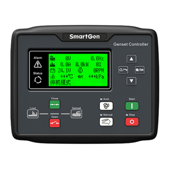
Page 11: Controller Panel
Status indicator: won’t illuminate when genset is in standby mode; flashes 1 time per second in start or stop process and always illuminates when runs normally; for J1939 engines, press start key in auto mode or stop mode, ECU power will output and status indicator always illuminates. HGMS61 Genset Controller User Manual Page 11 of 47... -
Page 12: Automatic Start/Stop Operation
When entering “Genset at Rest”, genset will automatically judge if it has stopped. When genset has stopped, enter into standby mode; if genset fails to stop, controller will alarm (“Fail to Stop” alarm will be displayed on LCD). HGMS61 Genset Controller User Manual Page 12 of 47... -
Page 13: Manual Start/Stop Operation
5s, the controller will send Failed To Charge warning and it well be displayed on LCD. 6 Battery Under Voltage When the battery voltage of genset is lower than threshold, controller will HGMS61 Genset Controller User Manual Page 13 of 47... - Page 14 “Warn”, it will send a warning alarm. When the controller receives warning signal from ECU via CAN it will 17 ECU Warn send a warning alarm. HGMS61 Genset Controller User Manual Page 14 of 47...
-
Page 15: Shutdown Alarms
LCD. When low fuel level input is active, controller will send a stop alarm 14 Low Fuel Level signal and it will be displayed on LCD. HGMS61 Genset Controller User Manual Page 15 of 47... - Page 16 21 ECU Shutdown send a shutdown alarm. If the controller does not receive the data via J1939 after starting the 22 ECU Comm. Failure engine, it will send a shutdown alarm. HGMS61 Genset Controller User Manual Page 16 of 47...
-
Page 17: Connections
Input HGMS61MCAN: connect CANBUS, 0.5mm Speed Sensor Input impedance-120Ω shielding wire is recommended, its Or ECU CAN Input single-end connect with ground. 0.5mm HGMS61M: connect to speed sensor, shielding wire HGMS61 Genset Controller User Manual Page 17 of 47... - Page 18 Connect Terminal 6 (B+ OUT) to this terminal B+ IN 2.5mm through a power switch to supply for positive post of HGMS61M. B+ OUT1 1.5mm Supply power to positive post of HGMS61D. 2.5mm Negative post of controller power. HGMS61 Genset Controller User Manual Page 18 of 47...
- Page 19 This terminal inside is connected with Main Terminal Mains N Wire Input 1.0mm Connect to Terminal N of charger. Note: USB ports in controller rear panel are programmable parameter ports; user can directly program via PC. HGMS61 Genset Controller User Manual Page 19 of 47...
-
Page 20: Hgms61D Controller Rear Panel
7.1 PARAMETER CONTENT AND RANGE TABLE Table 11 – Parameter Content and Range Items Range Default Description Time from mains abnormal or remote start Start Delay (0~3600)s signal is active to start genset. HGMS61 Genset Controller User Manual Page 20 of 47... - Page 21 “Gen Abnormal Delay”, Gen Under Voltage generator under voltage is active and it send (30~60000)V Shutdown generator abnormal stop alarm. When set as 30V, the under voltage signal is not detected. HGMS61 Genset Controller User Manual Page 21 of 47...
- Page 22 Failed To Charge warning. When battery voltage is over the value and Battery Over Voltage (12.0~40.0)V 33.0 remains for 20s, battery over voltage signal is active. it only warn but not shutdown. HGMS61 Genset Controller User Manual Page 22 of 47...
- Page 23 Digital Input 4 Delay (0~20.0)s 0: Stop Mode; 1: Manual Mode; 2: Auto Power On Mode (0~2) Mode Module Address (1~254) The communication address of controller. Password (0~9999) 0318 Module password. HGMS61 Genset Controller User Manual Page 23 of 47...
- Page 24 Start time and duration can be set. Auto Start Inhibited (0~1) 0:Disable; 1:Enable. Circulate condition: monthly, weekly and Scheduled Period (0~2) daily can be selected. Won’t start time and duration can be set. HGMS61 Genset Controller User Manual Page 24 of 47...
- Page 25 0:Disabled 1:Enable. When it is enabled, it is Active Power active power/rated power*100; when it is (0~1) Loading Percentage disabled, it is average current of the 3-phase/rated current*100; Charger Voltage (0~1) 0: Controller; 1: ECU Sampling Options HGMS61 Genset Controller User Manual Page 25 of 47...
-
Page 26: Programmable Output 1-4 Table
Including all shutdown alarm and warning alarm. When a warning Common Alarm alarm occurs, the alarm won’t self-lock; When a shutdown alarm occurs, the alarm will self-lock until alarm is reset. HGMS61 Genset Controller User Manual Page 26 of 47... - Page 27 Raising speed time is output while the unit entering into hi-speed Speed Raise Pulse warming up. Dropping speed time is output while the unit entering into stop Speed Drop Pulse idling. HGMS61 Genset Controller User Manual Page 27 of 47...
-
Page 28: Programmable Input 1-4 Table
Items Description This function only suits for HGMS61 CAN with engine type Yuchai-LMB. When unit is standby, pump control will output per 30 Oil Pump Control minutes. If oil pressure is above 100kPa or output delay is more than 1minute, it will stop output; if unit is in pre-heating state, oil pump control will always output. - Page 29 If engine type is common J1939, when input is active, engine Raise Speed Pulse target speed will increase 5RPM. If engine type is common J1939, when input is active, engine Drop Speed Pulse target speed will decrease 5RPM. HGMS61 Genset Controller User Manual Page 29 of 47...
-
Page 30: Sensor Selection
4 User Defined (4-20mA) SGD sensor. 5 User Defined (0-5V) 6 Digital Closed 7 Digital Open Note: it needs special instructions for ordering when the genset use 4-20mA or 0-5V sensors. HGMS61 Genset Controller User Manual Page 30 of 47... -
Page 31: Conditions Of Crank Disconnect
If generator frequency has not been selected, controller will not measure and display the relative parameters (can be applied to the pump set); if speed has not been selected, the rotating speed will be calculated by the generating AC signal. HGMS61 Genset Controller User Manual Page 31 of 47... -
Page 32: Parameter Setting
User may select display language as Chinese, English, Spanish, Russian, Portuguese, Turkey, Polish and French. LCD contrast ratio adjustment Press ) and adjust LCD contrast ratio, which shall make the LCD characters clearer. Adjustment range is 0-9. HGMS61 Genset Controller User Manual Page 32 of 47... -
Page 33: Sensor Setting
Before operation, the following checking should be carried out: — Check and ensure all the connections are correct and wires diameter is suitable. — Ensure that the controller DC power has fuse; battery positive and negative have correctly connected. HGMS61 Genset Controller User Manual Page 33 of 47... - Page 34 — Select the Auto Mode from front panel. After remote start signal is active, genset will start automatically and run in normal status, and then send gen close order to make geset take load. — If there are any other questions, please contact SmartGen’s service. HGMS61 Genset Controller User Manual...
-
Page 35: Typical Application
11 TYPICAL APPLICATION Fig.5 – HGMS61 Typical Application Diagram Fig.6 – HGMS61CAN Typical Application Diagram HGMS61 Genset Controller User Manual Page 35 of 47... -
Page 36: Installation
— Turn the fixing clip screws clockwise until they make contact with the panel. Note: 0.27N·m (2.75kgf·cm) torque is recommended to tighten the fixing clips. 12.2 OVERALL DIMENSION AND PANEL CUTOUT Unit: mm Fig. 9 – HGMS61D Case and Overall Dimensions HGMS61 Genset Controller User Manual Page 36 of 47... - Page 37 Fig.10 – HGMS61M Case and Overall Dimensions HGMS61 controller can be applicable to (8~35) VDC battery voltage. Battery negative must be reliably connected to engine shell. The connection between controller power and battery should not be less than 2.5mm . If a float charger is fitted, please connect output line of the charger with battery directly, and then connect battery positive and negative to power input of controller separately, in case that charger will interfere with the normal running of controller.
-
Page 38: Connections Of Controller With J1939 Engine
CAN communication shielding line(connect SAE J1939 shield-E to ECU terminal only) CAN(H) SAE J1939 signal-C Using impedance 120Ω connecting line CAN(L) SAE J1939 return-D Using impedance 120Ω connecting line Engine type: CUMMINS-CM850 HGMS61 Genset Controller User Manual Page 38 of 47... -
Page 39: Cummins Qsm11 (Import)
CAN communication shielding line(connect SAE J1939 shield-E to ECU terminal only) CAN(H) SAE J1939 signal-C Using impedance 120Ω connecting line CAN(L) SAE J1939 return-D Using impedance 120Ω connecting line Engine type: CUMMINS -CM570 HGMS61 Genset Controller User Manual Page 39 of 47... -
Page 40: Cummins Gcs-Modbus
Programmable output1 Output”. Start relay output Connect with starter coil directly CAN communication shielding line CAN(H) Using impedance 120Ω connecting line CAN(L) Using impedance 120Ω connecting line Engine type: common J1939 HGMS61 Genset Controller User Manual Page 40 of 47... -
Page 41: Cummins Qsz13
Start relay output Connect to starter coil directly CAN communication shielding line CAN(H) CAN(H) Using impedance 120Ω connecting line CAN(L) CAN(L) Using impedance 120Ω connecting line Engine type: J1939 common used HGMS61 Genset Controller User Manual Page 41 of 47... -
Page 42: Deutz Emr2
Terminals of controller SMART (X4 port) Remark X4 3 CAN communication shielding line CAN(H) X4 1 Using impedance 120Ω connecting line CAN(L) X4 2 Using impedance 120Ω connecting line Engine type: MTU-ADEC HGMS61 Genset Controller User Manual Page 42 of 47... -
Page 43: Mtu Adec (Sam Module)
Set configurable output 1 as “Fuel Relay Output” Start relay output Connect to starter coil directly CAN communication shielding line CAN(H) Using impedance 120Ω connecting line CAN(L) Using impedance 120Ω connecting line Engine type: SCANIA HGMS61 Genset Controller User Manual Page 43 of 47... -
Page 44: Volvo Edc3
Start relay output Connect to starter coil directly Connected to negative of battery CAN communication shielding line Using impedance 120Ω connecting line CAN(H) Using impedance 120Ω connecting line CAN(L) Engine type: VOLVO-EDC4 HGMS61 Genset Controller User Manual Page 44 of 47... -
Page 45: Volvo-Ems2
1.34 Using impedance 120Ω connecting line Table 43 – Engine 2 Pins Port Battery Engine 2 pins Remark Battery negative Wire diameter 2.5mm Battery positive Wire diameter 2.5mm Engine type: BOSCH HGMS61 Genset Controller User Manual Page 45 of 47... -
Page 46: Weichai
Output”. Connect to engine ignition lock Start relay output 1.61 CAN communication shielding line CAN(H) 1.35 Using impedance 120Ω connecting line CAN(L) 1.34 Using impedance 120Ω connecting line Engine type: GTSC1 HGMS61 Genset Controller User Manual Page 46 of 47... -
Page 47: Fault Finding
Check if COM port is correct; RS485 Failure Check if A and B of RS485 is connected reversely; Check if PC COM port is damaged; 120Ω resistance between RS485 and AB is Recommended. _________________________________ HGMS61 Genset Controller User Manual Page 47 of 47...
Need help?
Do you have a question about the HGMS61 and is the answer not in the manual?
Questions and answers