Table of Contents
Advertisement
Quick Links
Advertisement
Table of Contents

Subscribe to Our Youtube Channel
Related Manuals for Smartgen HGM9510


Summary of Contents for Smartgen HGM9510
- Page 1 HGM9510 Genset Parallel (With Genset) Unit USER MANUAL Smartgen Technology...
- Page 2 All rights reserved. No part of this publication may be reproduced in any material form (including photocopying or storing in any medium by electronic means or other) without the written permission of the copyright holder. Smartgen Technology reserves the right to change the contents of this document without prior notice. Version history...
-
Page 3: Table Of Contents
HGM9510 GENSET PARALLEL UNIT CONTENTS 1 OVERVIEW ....................... 5 2 MODULES COMPARISON ................6 3 PERFORMANCE AND CHARACTERISTICS ........... 7 4 SPECIFICATION ....................9 5 OPERATION ....................10 INDICATOR LIGHT ......................10 PUSHBUTTONS ......................10 LCD DISPLAY ....................... 11 5.3.1 MAIN DISPLAY ......................11 5.3.2 USER MENU AND PARAMETERS SETTING MENU .......... - Page 4 HGM9510 GENSET PARALLEL UNIT 11.1 STEP 1. SINGLE UNIT DEBUGGING ................49 11.2 STEP 2: MANUAL PARALLEL OPERATION OFF-LOAD ..........49 11.3 STEP 3: MANUAL PARALLEL OPERATION ON-LOAD ..........49 11.4 STEP 4: AUTOMATIC PARALLEL OPERATION ............50 12 TYPICAL APPLICATION ................51 13 INSTALLATION ....................
-
Page 5: Overview
HGM9510 GENSET PARALLEL UNIT 1 OVERVIEW HGM9510 controller is designed for manual/auto parallel system generators with similar or different capacity. Additionally, it is suitable for single unit constant power output and mains paralleling. It allows automatic start/stop, parallel running, data measurement, alarm protection as well as remote control, remote measurement and remote communication function. -
Page 6: Modules Comparison
Micro SD card NOTE: (1) Two of the outputs are fixed: start output and fuel output. (2)HGM9510’s analog sensors are composed by 3 fixed sensors (temperature, pressure, level) and 2 configurable sensors. NOTE: The features of HGM9210/HGM9220/HGM9310/HGM9320/HGM9410/ HGM9420/HGM9520/HGM9610/HGM9620 controllers mentioned in this document may change, please check the corresponding user manual for accurate information. -
Page 7: Performance And Characteristics
HGM9510 GENSET PARALLEL UNIT 3 PERFORMANCE AND CHARACTERISTICS With ARM-based 32-bit SCM, high integration of hardware and more reliable; 480x272 LCD with backlight, multilingual interface (including English, Chinese or other languages) which can be chosen at the site, making commissioning convenient for factory personnel;... - Page 8 HGM9510 GENSET PARALLEL UNIT Start times can accumulate Max. 65535 times Protection: automatic start/stop of the gen-set, ATS(Auto Transfer Switch) control with perfect fault indication and protection function; All output ports are relay output; Parameter setting: parameters can be modified and stored in internal EEPROM memory and cannot be lost even in case of power outage;...
-
Page 9: Specification
HGM9510 GENSET PARALLEL UNIT 4 SPECIFICATION Parameter Details Working Voltage DC8. 0V to 35. 0V, uninterruptible power supply <4W (Standby mode: ≤2W) Overall Consumption AC Input: 3 Phase 4 Wire AC 15V - 360V (ph-N) 3 Phase 3 Wire AC 30V - 620V (ph- ph) -
Page 10: Operation
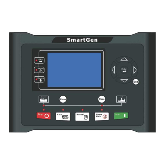
HGM9510 GENSET PARALLEL UNIT 5 OPERATION 5.1 INDICATOR LIGHT NOTE: Selected light indicators description: Warning indicator and Alarm indicator: Alarm Type Warning Indicator Alarm Indicator Warning Slow flashing Slow flashing Trip Alarm Slow flashing Slow flashing Shutdown Alarm Fast flashing... -
Page 11: Lcd Display
WARNING: Default password is 00318, user can change it in case of others change the advanced parameters setting. Please clearly remember the password after changing. If you forget it, please contact Smartgen services and send all information in the controller page of “ABOUT” to 5.3 LCD DISPLAY 5.3.1 MAIN DISPLAY... - Page 12 HGM9510 GENSET PARALLEL UNIT Status of genset and ATS ★Engine, including as below, Engine speed, engine temperature, engine oil pressure, fuel level, flexible sensor 1, flexible sensor 2, battery voltage, charger voltage, engine accumulated run, accumulated start times. NOTE: If connected with J1939 engine via CANBUS port, this page also includes: coolant pressure, coolant level, fuel temperature, fuel pressure, inlet temperature, exhaust temperature, turbo pressure, total fuel consumption and so on.
-
Page 13: User Menu And Parameters Setting Menu
HGM9510 GENSET PARALLEL UNIT Volt difference, freq difference, angle difference, active power percentage, target active power percentage, reactive power percentage, target reactive power percentage, GOV percentage, AVR percentage and MSC status ★Alarm: NOTE: For ECU alarms and shutdown alarms, if the alarm information is displayed, check engine according to it, otherwise, please check the generator manual according to SPN alarm code. - Page 14 HGM9510 GENSET PARALLEL UNIT ★Scheduling and maintenance settings ★Synchronization settings Return >Start Delay Form1: Use to scroll settings, >Return Delay Timers > to enter settings (form 2), to exit >Preheat Delay Engine >Cranking Time Generator settings menu. >Crank Rest Time Load >Safety On Time...
- Page 15 HGM9510 GENSET PARALLEL UNIT > Start Delay Form 4: Press to enter settings (form > Return Delay 00008 to return to previous menu. (form 6). > Preheat Delay > Cranking Time >Crank Rest Time > Safety On Time > Start Idle Time >...
-
Page 16: Auto Start/Stop Operation
HGM9510 GENSET PARALLEL UNIT 5.4 AUTO START/STOP OPERATION Auto mode is selected by pressing the button; a LED besides the button will illuminate to confirm the operation. Automatic Start Sequence: 1. When “Remote Start” is active, “Start Delay” timer is initiated;... -
Page 17: Manual Start/Stop Operation
HGM9510 GENSET PARALLEL UNIT Note: When started via “Remote Start (off Load)” input, same procedures as above but generator close relay deactivated, moreover, genset off load. When started via “Remote Start (Demand)” input,the genset will start, synchronization, parallel and load sharing automatically according to the pre-set priority order. -
Page 18: Automatic Control Procedure
HGM9510 GENSET PARALLEL UNIT Closing Operation: During genset normal running, press if generator voltage and frequency have reached on-load requirements 1) In case of single unit running, generator closing relay outputs; 2) In case of running in parallel: a) If bus has no voltage, then the controller will send a closing signal to other waiting parallel gensets and generator close relay will activate, this prevents other sets in the system from attempting to close their own breakers at the same time. -
Page 19: Protections
HGM9510 GENSET PARALLEL UNIT 6 PROTECTIONS 6.1 WARNING ALARMS Warnings are not shutdown alarms and do not affect the operation of the gen-set. Warning alarms does not lead to shutdown. Warning alarms types are as follows: Type Description When the controller detects that the engine speed has exceeded Over Speed the pre-set value, it will initiate a warning alarm. - Page 20 HGM9510 GENSET PARALLEL UNIT Type Description When the controller detects that the breaker close or open failure occurs, and the action select “Warn”, it will initiate a warning Switch Fail Warn alarm. Temperature Sensor When the controller detects that the temperature sensor is open circuit and the action select “Warn”, it will initiate a warning alarm.
-
Page 21: Shutdown Alarms
HGM9510 GENSET PARALLEL UNIT 6.2 SHUTDOWN ALARMS When controller detects shutdown alarm, it will send signal to open breaker and shuts down generator. Shutdown alarms as following: Type Description When the controller detects an emergency stop alarm signal, it will Emergency Stop initiate a shutdown alarm. - Page 22 HGM9510 GENSET PARALLEL UNIT Type Description When the controller detects that the oil pressure sensor is open Oil Pressure Open circuit and the action select “Shutdown”, it will initiate a shutdown Circuit alarm. When the controller detects that the oil pressure has fallen below Low Oil Pressure the pre-set value, it will initiate a shutdown alarm.
-
Page 23: Trip And Stop Alarms
HGM9510 GENSET PARALLEL UNIT 6.3 TRIP AND STOP ALARMS On initiation of the trip and stop condition the controller will de-energize the ‘Close Generator’ Output to remove the load from the generator. Once this has occurred the controller will start the Cooling delay and allow the engine to cool before shutting down the engine. -
Page 24: Trip Alarm
HGM9510 GENSET PARALLEL UNIT 6.4 TRIP ALARM On initiation of the trip condition the controller will de-energize the ‘Close Generator’ Output without stop the generator. Trip alarm as following, Type Description When the controller detects that the genset current has exceeded the pre-set value and the action select “Trip”, it will initiate a trip... -
Page 25: Wiring Connection
HGM9510 GENSET PARALLEL UNIT 7 WIRING CONNECTION HGM9510 controller’s rear as following: Description of terminal connection: Cable Functions Remark Size DC input B- 2.5mm Connected with negative of starter battery. Connected with positive of starter battery. If wire DC input B+ 2.5mm... - Page 26 HGM9510 GENSET PARALLEL UNIT Cable Functions Remark Size Magnetic Pickup Connected with Speed sensor, shielding line is Shielding 0.5mm recommended. (B-) has already connected with speed sensor 2. Details Aux. input 7 1.0mm Ground connected is active (B-) form 3...
- Page 27 HGM9510 GENSET PARALLEL UNIT Cable Functions Remark Size CT A-phase sensing Outside connected to secondary coil of current 1.5mm input transformer(rated 5A) CT B-phase sensing Outside connected to secondary coil of current 1.5mm input transformer(rated 5A) CT C-phase sensing Outside connected to secondary coil of current 1.5mm...
-
Page 28: Scopes And Definitions Of Programmable Parameters
HGM9510 GENSET PARALLEL UNIT 8 SCOPES AND DEFINITIONS OF PROGRAMMABLE PARAMETERS 8.1 CONTENTS AND SCOPES OF PARAMETERS Form 1 Items Parameters Defaults Description Timer Setting Time from mains abnormal or remote Start Delay (0~3600)s start signal is active to start genset. - Page 29 HGM9510 GENSET PARALLEL UNIT Items Parameters Defaults Description of starter separation conditions and inspecting of engine speed. See the installation instructions. Offer standard judge Rated Speed (0~6000)RPM 1500 over/under/loading speed. Setting value is percentage of rated speed. Controller detects when it is...
- Page 30 HGM9510 GENSET PARALLEL UNIT Items Parameters Defaults Description See form 5 There are 3 conditions of disconnecting starter with engine. Each condition can Crank Disconnect (0~6) be used alone and simultaneously to separating the start motor and genset as soon as possible.
- Page 31 HGM9510 GENSET PARALLEL UNIT Items Parameters Defaults Description can be set. Setting value is percentage of generator Over Freq. (0~200)% rated freq. Delay value (default: 2s) also Shutdown can be set. Setting value is percentage of generator Under Freq. (0~200)% rated freq.
- Page 32 HGM9510 GENSET PARALLEL UNIT Items Parameters Defaults Description rated reactive power. Delay value (default: 5s) and action (default: trip) can be set. Switch Setting Pulse width of mains/generator switch Close Time (0~20.0)s on. When it is 0, means output constantly.
- Page 33 HGM9510 GENSET PARALLEL UNIT Items Parameters Defaults Description this value. Detecting only after safety delay is over. The delay value (default: 3s) also can be set. Warn when oil pressure higher than this value. Detecting only after safety delay Low OP Warn (0~1000)kPa is over.
- Page 34 HGM9510 GENSET PARALLEL UNIT Items Parameters Defaults Description 3:Trip 4: Indication Active Delay (0~20.0)s Time from detecting active to confirm LCD display detailed contents when the Description input is active. Flexible Input Port 6 Contents Setting (0~50) First priority. See form 3...
- Page 35 HGM9510 GENSET PARALLEL UNIT Items Parameters Defaults Description Sync Setting -Basic It is considered Bus no power when Bus Dead Bus Volt (10-50)V voltage is lower than dead Bus voltage. It is considered voltage synchronization when the voltage difference between...
- Page 36 HGM9510 GENSET PARALLEL UNIT Items Parameters Defaults Description signal during the preset delay, it will send corresponding alarm signal Fail to Sync Action (0-1) according to the action type. Action Type: 0:Warn;1:Trip. (Load (0-1) Shedding) Trip NEL Trip 1 Set...
- Page 37 HGM9510 GENSET PARALLEL UNIT Items Parameters Defaults Description Voltage Range (0-10.0) Default volt. range: (-2.5~+2.5)V Sync Gain (0-500) Adjust and control before paralleling. Sync Stability (0-2000) Adjust and control before paralleling. Load Gain (0-500) Adjust and control after paralleling. Load Stability (0-2000) Adjust and control after paralleling.
-
Page 38: Enable Definition Of Programmable Output Ports
HGM9510 GENSET PARALLEL UNIT T = t / ((IA/IT)-1) T:Overcurrent delay (second) t:Timing multiplier ratio IA:Current max. load current(L1/L2/L3) IT:Overcurrent setting value Example: t = 36 IA = 550A IT =500A Conclusion: T = 3600s(1hour) 8.2 ENABLE DEFINITION OF PROGRAMMABLE OUTPUT PORTS... - Page 39 HGM9510 GENSET PARALLEL UNIT threshold. Action from “crank on” to “safety on”. Oil Pre-supply Output Output in start period. If there is no generator frequency Generator Excite during hi-speed running, output for 2 seconds again. Pre-Lubricate Actions in period of pre-heating to safety run.
- Page 40 HGM9510 GENSET PARALLEL UNIT Reserved Reserved Reserved ECU Warning Indicate ECU sends a warning signal. ECU Shutdown Indicate ECU sends a shutdown signal. ECU Com Fail Indicate controller not communicates with ECU. When output type of AVR set as “Relay output”, controller PWM Voltage Raise adjust voltage and reactive power via “Sync Raise Volt”...
-
Page 41: Defined Period Output
HGM9510 GENSET PARALLEL UNIT Generator Reverse Action when controller detects generator have reverse Power power. Over Current Action when over current. NEL1 Trip Details of function description please see the following. NEL2 Trip NEL3 Trip 127~138 Reserved High Temp Warn Action when hi-temperature warning. -
Page 42: Defined Combination Output
HGM9510 GENSET PARALLEL UNIT While S1 and S2 are TRUE synchronously, OUTPUT; While S1 or S2 is FALSE, NOT OUTPUT. Period output S1, can set generator’s one or more period output freely, can set the delayed time and output time after enter into period. -
Page 43: Defined Contents Of Programmable Input Ports
HGM9510 GENSET PARALLEL UNIT Close when probably condition output S3 is active /inactive: close when active (disconnect when inactive); When input port 1 active or input port 2 active, if input port 3 is active, Defined combination output is outputting; If input port 3 inactive, Defined combination output is not outputting;... - Page 44 Simulate Auto key An external button can be connected and pressed as simulate panel. Simulate Start key This is simulate G-close key when HGM9510 controller Simulate G-Load key is applied. This is simulate M-open key when HGM9510 controller Simulate M-Load key is applied.
-
Page 45: Selection Of Sensors
HGM9510 GENSET PARALLEL UNIT NEL Manual Recon Details of function description please see the following. Power management mode will be displayed on the LCD when the input is active. In this mode, the controller will control genset synchronize, power sharing, scheduled... -
Page 46: Conditions Of Crank Dinsconnect Selection
HGM9510 GENSET PARALLEL UNIT Description Remark 0 Not used 1 Custom Res Curve Defined resistance’s range is 2 Custom 4-20mA curve Oil Level Sensor 0~6KΩ, default is SGH sensor. 3 SGD 4 SGH 5~15 Reserved NOTE: User should make special declare when order controller if your genset equip with sensor of 4~20mA. -
Page 47: Parameters Setting
HGM9510 GENSET PARALLEL UNIT 9 PARAMETERS SETTING CAUTION: Please change the controller parameters when generator is in standby mode only (e. g. Start conditions selection, configurable input, configurable output, various delay), otherwise, alarming to stop and other abnormal conditions may happen. -
Page 48: Sensors Setting
HGM9510 GENSET PARALLEL UNIT 10 SENSORS SETTING 10.1 When reselect sensors, the sensor curve will be transferred into the standard value. For example, if temperature sensor is SGX (120° C resistor type), its sensor curve is SGX (120° C resistor type); if select the SGD (120° C resistor type), the temperature sensor curve is SGD curve. -
Page 49: Commissioning
1) Manually close parallel sets, check that the units synchronization is balanced and breaker close impulse current is not too high; 2) During parallel operation off load, check that there is no high circumfluence on HGM9510 current screen; 3) During parallel operation off load, check if the output of active and reactive power is equal to zero;... -
Page 50: Step 4: Automatic Parallel Operation
HGM9510 GENSET PARALLEL UNIT 4) During manual parallel, perform impact load test and damp load test to check if there is power oscillation. 11.4 STEP 4: AUTOMATIC PARALLEL OPERATION When the controller is in auto status, if digital input “remote start on-load (on demand)” is active, it will carry out automatic parallel, start and stop operation. -
Page 51: Typical Application
HGM9510 GENSET PARALLEL UNIT 12 TYPICAL APPLICATION HGM9510 typical application diagram Note: Fuse F1:min. 2A; max. 20A. Fuse F2:max. 32A. Users should select suitable fuse depend on practical application. 3 Phase 3 Wire 2 Phase 3 Wire Single Phase 2 Wire... - Page 52 HGM9510 GENSET PARALLEL UNIT HGM9510 Multi-genset Parallel Application Note: Mains parallel function for HGM9510 controller can be selected via configurable input port. In mains parallel mode, generator will run in parallel with mains and it will only be able to output a fixed amount of power. (Set load mode as Gen control mode).
- Page 53 HGM9510 GENSET PARALLEL UNIT 13 POWER MANAGEMENT MODE Power management mode can be selected via configurable input ports. HGM9510 Genset Parallel Unit ISSUE 2013-08-06 Version 1.1 Page 53 of 65...
- Page 54 HGM9510 GENSET PARALLEL UNIT 14 LOAD SHEDDING Non-essential load ---- NEL for short. The controller can control the NEL1, NEL2 and NEL3 to trip separately. The order of the essentiality is: NEL3 > NEL2 > NEL1 Auto trip: When NEL auto trip is enabled: If the genset power has exceed the NEL trip value, after the trip delay, NEL1 will trip the earliest, and then is NEL2,NEL3;...
-
Page 55: Installation
Battery Voltage Input NOTE: HGM9510 controller can suit for widely range of battery voltage (8~35) VDC. Negative of battery must be connected with the shell of starter stable. The wire’s diameter must be over 2.5mm... - Page 56 HGM9510 GENSET PARALLEL UNIT transformer and input voltage must correct. Otherwise, the current of collecting and active power maybe not correct. NOTE: ICOM port must be connected to negative pole of battery. WARNING! When there is load current, transformer’s secondary side prohibit open circuit.
-
Page 57: Connections Of Controller With J1939 Engine
HGM9510 GENSET PARALLEL UNIT 16 CONNECTIONS OF CONTROLLER WITH J1939 ENGINE 16.1 CUMMINS ISB/ISBE Terminals of controller Connector B Remark Fuel relay output Start relay output Connect with starter coil directly Expand 30A relay, battery ECU power Set configurable output 1 as “ECU... -
Page 58: Cummins Qsm11(Import)
HGM9510 GENSET PARALLEL UNIT 16.3 CUMMINS QSM11(IMPORT) It is suitable for CM570 engine control module. Engine type is QSM11 G1, QSM11 G2. Terminals of controller C1 connector Remark Outside expand relay, when fuel output, Fuel relay output 5&8 making port 5 and port 8 of C1 be... -
Page 59: Cummins Qsm11
HGM9510 GENSET PARALLEL UNIT 16.6 CUMMINS QSM11 Terminals of controller OEM connector of engine Remark Fuel relay output Start relay output Connect with starter coil directly CAN GND communication shielding line(connect with controller’s this terminal only) Using impedance 120Ω connecting line CAN(H) Using impedance 120Ω... -
Page 60: Deutz Emr2
HGM9510 GENSET PARALLEL UNIT 16.9 DEUTZ EMR2 Terminals of controller F connector Remark Expand relay, battery voltage of 14 is Fuel relay output supplied by relay. Fuse is Start relay output Connect to starter coil directly Connect to battery negative pole... -
Page 61: Mtu Adec(Smart Module)
HGM9510 GENSET PARALLEL UNIT 16.12 MTU ADEC(SMART MODULE) It is suitable for MTU engine with ADEC (ECU8) and SMART module. Terminals of controller ADEC (X1port) Remark Fuel relay output X1 10 X1 Terminal 9 Connected to negative of battery Start relay output... -
Page 62: Scania
HGM9510 GENSET PARALLEL UNIT 16.15 SCANIA It is suitable for S6 engine control module. Engine type is DC9, DC12, and DC16. Terminals of controller B1 connector Remark Fuel relay output Start relay output Connect to starter coil directly communication shielding line(connect with controller’s terminal... -
Page 63: Volvo-Ems2
Using impedance 120Ω connecting line CAN(L) 1.34 Engine type: GTSC1 NOTE: If there is any question of connection between controller and ECU communication, please feel free to contact Smartgen’s service. HGM9510 Genset Parallel Unit ISSUE 2013-08-06 Version 1.1 Page 63 of 65... -
Page 64: Usb
HGM9510 GENSET PARALLEL UNIT 17 USB Users can set the controller’s parameters and monitor the controller’s status via the test software which provided by Smatgen company. The connection way between PC and controller as following: HGM9510 Genset Parallel Unit ISSUE 2013-08-06 Version 1.1... -
Page 65: Fault Finding
HGM9510 GENSET PARALLEL UNIT 18 FAULT FINDING Symptoms Possible Solutions Check starting batteries; Controller no response with Check controller connection wirings; power. Check DC fuse. Check the water/cylinder temperature is too high or not; Genset shutdown Check the genset AC voltage;...
Need help?
Do you have a question about the HGM9510 and is the answer not in the manual?
Questions and answers