
Subscribe to Our Youtube Channel
Related Manuals for Teledyne VISION G2 CLASSIC 6


Summary of Contents for Teledyne VISION G2 CLASSIC 6
- Page 1 ® ™ ™ G2 C ISION LASSIC LITE ISSOLUTION ESTERS UIDE 74-108-800-Rev. H—12 June 2019...
- Page 2 About Teledyne Hanson Research Teledyne Hanson Research, a division of Teledyne Instruments, Inc., is a global technology company specializing in analytical test instruments for the pharmaceutical industry. Founded by the innovator of modern dissolution test technology, Teledyne Hanson Research (THR) helps ensure the world’s...
- Page 3 Sales and Support Congratulations on your purchase of the Teledyne Hanson Research Vision G2 dissolution tester. While we are certain you will enjoy this new product, we also understand from time to time you may have a question or technical issue requiring our assistance.
- Page 4 Added three-tier security. Updated document 12 June 2019 to Teledyne format. To confirm that you have received the latest version of this user guide, contact Teledyne Hanson Research Technical Support. Vision G2 Testers User Guide—74-108-800 Rev. H—12 June 2019 3 of 158...
-
Page 5: Table Of Contents
Table of Contents Table of Contents INTRODUCTION .......................... 7 ............................ 7 EFINITIONS ............................. 10 EATURES ...................... 11 ISION ESTER DENTIFICATION ........................ 13 EARNING THE NTERFACE REGULATORY AND SAFETY ...................... 22 ...................... 22 ENERAL AFETY ONSIDERATIONS ......................... 22 ... - Page 6 Table of Contents MAINTENANCE ........................... 120 .................... 120 CHEDULED AINTENANCE VERVIEW O‐R .................... 121 ING NSPECTION AND EPLACEMENT .......................... 121 ELT EPLACEMENT .................. 122 EATER AND EMPERATURE ROBE DJUSTMENT ...................... 123 PINDLE HAFT EIGHT DJUSTMENT ........................ 123 OVING AND TORAGE ...
- Page 7 Table of Contents ........................ 156 SING AN VENT IBRARY .................. 157 XAMPLES OF OW TO SE AN VENT IBRARY Figures and Diagrams A‐1 ................ 11 IGURE DENTIFICATION ISION LASSIC ESTER A‐2 ................... 12 IGURE DENTIFICATION ISION LITE ...
-
Page 8: Introduction
We have applied 60 years of innovation and expertise to the design and manufacture of these quality test systems. At Teledyne Hanson Research, we combine art with science and engineering. We apply elegant design and instrument ergonomics to the rigors and everyday challenges of scientific investigation, research, and analysis. - Page 9 Introduction DissoScan™ The autosampler with one 3-way solenoid valve per syringe to direct fluid flow. The DissoScan provides 2 fluid lines (A and D). One tester can be connected to a DissoScan. Easi-Lock™ The system used by Vision vessels that allows them to be locked into place.
- Page 10 Vision® AutoFilter™ A programmable filter changing instrument which uses 25 mm in-line syringe filters. Vision® AutoPlus™ The redesigned Teledyne Hanson autosampler series (either Maximizer or DissoScan) with stepper motor driven syringes. Vision® G2 Teledyne Hanson Vision® “G2” dissolution instruments represent a significant upgrade from the original Vision testers introduced in 2008.
-
Page 11: Features
Introduction Features The new Vision G2 dissolution testers take the next step in dissolution testing with a streamlined new design and increased functionality. Here are some of the new features Classic 6 Elite 8 Standard Features Fixed drive head ... -
Page 12: Vision G2 Tester Identification
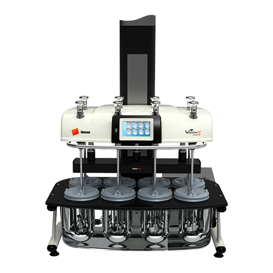
Introduction Vision G2 Tester Identification Figure A-1 Identification: Vision G2 Classic 6 Tester Shaft clamp Power switch Touchscreen Vision heater Spindle shaft Vision G2 Testers User Guide—74-108-800 Rev. H—12 June 2019 11 of 158... - Page 13 Introduction Figure A-2 Identification: Vision G2 Elite 8 Tester Touchscreen Shaft clamp Drive Power switch head handle AutoMag Spindle shaft Vision heater Vision G2 Testers User Guide—74-108-800 Rev. H—12 June 2019 12 of 158...
-
Page 14: Learning The Interface
Introduction Learning the Interface The Vision G2 dissolution tester software was designed to be intuitive and easy to use. A user is able to interact and program the unit using the touchscreen interface. The touchscreen can be used with fingers or with a stylus. The interface has the following forms of input: Buttons: In order to use a button, touch it with your finger or a stylus. - Page 15 Introduction To cancel out of the screen, touch the ESC button. NOTE: Touching the (X) in the input line clears in the whole line. Numeric Keypad: The numeric keypads are used for numeric entry into the unit. Unlike the text keypads, numeric keypads often have limits or specific formats which must be observed when entering information.
- Page 16 Introduction Calendar When setting dates, a calendar screen will be displayed. Touch the arrows located at the bottom of the calendar screen to select the month. Touch the day of the date displayed to select that date. Tab buttons The tab buttons are located on the left side of the screen and allow access to different parts of a section of the software.
- Page 17 Introduction Send button The Send button allows the user to print the displayed logs to the printer or upload them to a USB flash drive. This is a common button on many of the screens of the Vision tester. NOTE: For ease of reading, it is recommended to open logs in a word processor.
- Page 18 Introduction After the initialization sequence completes, the unit remains at the home screen. The home screen displays the motor speed (rpm), motor speed set point, temperature, temperature set point, elapsed test time, and a countdown until the next event. If no test is running, the times will be listed as 0:0000. The motor speed and temperature are displayed on the left side of the screen.
- Page 19 Introduction NOTE: If a Quick Start speed is not set, the Elapsed Time field will not respond when touched. To adjust the temperature, touch the current temperature on the home screen and a numeric keypad will appear. If there is a problem with the external temperature probe, “Probe Error”...
- Page 20 Introduction Touching the Vessels button brings up the Vessels screen, which displays the current temperature in the vessels. On the left side of the Vessels screen, you have the option of raising or lowering the probes using the Raise or Lower arrows (if AutoMag or SuperMag is installed), and/or printing the vessel temperatures using the Print button.
- Page 21 Introduction The menu is accessed by touching the Menu button located in the bottom left corner of the screen. If a protocol is already loaded, the protocol name will appear in the upper left corner of the screen, and when touched it will be opened for editing.
- Page 22 Introduction If security features are enabled, the current user is displayed in the upper right corner of the screen. If no user is logged on, and security features are enabled, Please Log In appears in the corner. If security features are not enabled, a user can log on by touching the same corner of the screen.
-
Page 23: Regulatory And Safety
Regulatory and Safety Regulatory and Safety General Safety Considerations This equipment contains moving parts, which have the potential to pinch or jam. The installation category (overvoltage category) for this instrument is Level II. The Level II category pertains to equipment that receives its electrical power from a local level, such as an electrical wall outlet. -
Page 24: Canadian Emissions Notice
Regulatory and Safety Canadian Emissions Notice This digital apparatus does not exceed the Class A limits for radio noise emissions from digital apparatus set forth in the Radio Interference Regulations of the Canadian Department of Communications. Le présent appareil numérique n’émet pas de bruits radioélectriques dépassant les limites applicables aux appareils numériques de la classe A prescrites dans les réglements sur le brouillage radioélectrique édictés par le Ministére des... -
Page 25: Installation
Installation Installation Location This section provides information on determining if a location is suited to a Vision G2 dissolution tester. Consideration should be made as to the final system layout design prior to placing any equipment on the bench. Environmental Requirements The location should be clean and free of any issues which may influence dissolution testing. -
Page 26: Unpacking And Inspection
DO NOT lift the instrument by the chrome handle. Unpack the Vision tester from the shipping container. a. Note any damage to the shipping container. If container is damaged, contact Teledyne Hanson Research immediately. b. Place shipping container near installation location. - Page 27 Installation g. If installing the Elite 8, the two locking bolts should be removed from the weight using the included hex wrench. There are no locking bolts on the Classic 6, as the drive head is fixed and not adjustable. Fig.
- Page 28 Installation Level the dissolution tester. Place a bubble level in the center of the vessel plate. Adjust the feet of the dissolution tester until the bubble level indicates the vessel plate is level. Fig. C-3 Bubble Level on a Leveled Tester i.
-
Page 29: Electrical Connections
Installation Electrical Connections Power port Fig. C-4 Vision G2 (Classic 6 and Elite 8) Back Panel Ports Power Power port Fig. C-5 Vision Heater Back Panel Ports This section provides instructions on making the power connections to the Vision tester. Ensure the power switch located on the right side of the Vision tester is in the off (O) position. -
Page 30: Vision Heater Installation
Installation Vision Heater Installation Place the Vision heater to the right rear side of the tester. Connect the tubing as shown in figure C-6 or C-7. Ensure hose clamps are on straight. Tighten the clamps 3 to 5 clicks to prevent leaks. NOTE: A pair of pliers is required for proper tightening of the hose clamps. - Page 31 Installation Fig. C-6 Classic 6 Bath to Heater Tubing Connection Fig. C-7 Elite 8 Bath to Heater Tubing Connection Vision G2 Testers User Guide—74-108-800 Rev. H—12 June 2019 30 of 158...
-
Page 32: Priming The Waterbath
Installation Priming the Waterbath Method 1 WARNING: Do not set a temperature during this procedure. Doing so may result in damage to the Vision heater. Fill the waterbath to the line on the sticker located at the center front of the bath. Fig. - Page 33 Installation Insert the end of the syringe assembly into the bath fitting that is mounted to the bottom of the bath. NOTE: Push the end of the syringe assembly down as far as possible. If the end of the assembly is too high, the water will not be pushed into the tubing.
- Page 34 Installation Go to the Temperature Setpoint screen and touch the PUMP button. WARNING: Do not set a temperature during this procedure. Doing so may result in damage to the Vision heater. Wait for consistent flow from the drain hose. When the pump has been primed, the noise from the Vision heater should decrease.
-
Page 35: Draining The Waterbath (Not Required For Installation)
Installation Draining the Waterbath (not required for installation) WARNING: Do not set a temperature during this process. Doing so may result in damage to the Vision heater. Remove a vessel over the bath output fitting. Insert the drain plug into the bath output fitting. This will allow the bath to drain completely. -
Page 36: Guidelines For Cleaning The Waterbath
Installation Connect the drain hose to the heater output. Go to the Temperature Setpoint screen and touch the PUMP button. When the bath is completely drained, touch the PUMP button again to stop the pump. Guidelines for Cleaning the Waterbath This section provides only guidelines for cleaning the waterbaths of the Classic 6 and Elite 8. -
Page 37: Verification Of Manual Controls
Installation Verification of Manual Controls This section provides instructions on how to test the manual controls to ensure the tester can perform basic functions. Turn on (I) the Vision heater with the power switch located on the back. Turn on (I) the tester using the power switch on right side of the drive head. - Page 38 Installation From the home screen, touch the Menu button to bring up the tester menu screen. Touch the Time button to bring up the Edit Alarms Screen. Vision G2 Testers User Guide—74-108-800 Rev. H—12 June 2019 37 of 158...
- Page 39 Installation The Edit Alarms screen will appear. Touch the Time/Date button at the bottom of the screen. The Edit Time/Date screen will appear. Touch the System Date field to set the current date. Enter the date in the DD-MM-YYYY format, and touch OK when done.
- Page 40 Installation Touch the Exit button at the bottom right corner of the screen to return to the main menu. Touch the Config button to bring up the system configuration screens. 10. The first tab is Instrument. Touch the Instrument ID field to edit the instrument ID for the tester.
- Page 41 Installation 11. Touch the IP Address field to edit the IP address. A numeric keypad will appear to allow the entry. The IP address must take the form of ###.###.###.###. To ensure proper communication, the first 3 sections of the IP address must match between the tester and sampler or printer.
-
Page 42: Liquid Line Connections
Installation Liquid Line Connections Sample line connections are made by connecting the six or eight liquid tubes from the Vision AutoPlus/AutoFill or other autosampler to the dissolution tester. These are numbered and color-coded for easy identification. They can be connected with nuts, unions, and ferrules as shown in the figure below: UNION FERRULE... - Page 43 Installation Firmware versions 2.70 and above offer Enhanced Security with three levels of users (administrators, managers and operators) with configurable permissions. Security settings To configure security settings, begin by selecting the Security button from the main menu and the Security Configuration screen will appear.
- Page 44 Installation The following settings are recommended for a manager. The following settings are recommended for an administrator. • Alarm Settings: Allows the configuration and resetting of the alarms for the instrument. • Instrument Config: Allows adjusting the instrument configuration settings such as whether a printer is connected to the instrument.
- Page 45 Installation • Run Tests: Allows the ability to run a protocol. Protocols can still be viewed or edited depending on the permissions provided. • Edit Informatics: Allows the editing of the system time, date, Instrument ID, and network configuration settings. Only users with permission to edit security settings can display the User List.
- Page 46 Installation Type: Toggles the type of user. The options are operator or manager; the default is operator. Status: The user's status. The options are locked or unlocked. An unlocked user has access to the system, a locked user does not and must be unlocked by a manager.
-
Page 47: Drive Head Movement (Elite 8 Only)
Installation Add: Allows a manager to create a new user. The screen that appears is identical to the Edit User Profile screen. Log Out: Logs out the current user Log In: With security enabled, a user can log on either by touching the upper right of the home screen where Please Log In or the name of the user who is logged in is displayed. -
Page 48: Vessel Cover Installation
Installation To release the paddle or basket shaft, grasp the shaft clamp, then rotate the paddle or basket shaft clockwise out of the spindle shaft. If the shaft releases with a slight pop it has been properly tightened. When the tester is in operation, ensure that the key of the shaft clamp and the key on the spindle itself are at the same level so that they will lock together. - Page 49 Installation Slide the cover so that the spindle shaft is located in the center hole and unfold the cover. The cover should rest on the vessel rim such that the notches fit around the raised keys of the vessel rim. ADD Cover for Vision Fig.
- Page 50 Installation Easi-Lock ADD CS Cover Fig. C-16 Easi-Lock ADD CS Cover 74-107-013 To install the ADD vessel cover, with the drive head down (Elite 8) and shafts in place: Open the cover and slide it around the shaft so that the spindle shaft is in the center of the cover.
- Page 51 Installation Easi-Lock CS Cover Fig. C-17 Easi-Lock CS Cover 74-107-012 To install the clam shell cover with the drive head down (Elite 8) and shafts in place: Open the cover and slide it around the shaft so that the spindle shaft is in the center of the cover. If an AutoMag is installed, align the cover with the sample probes.
-
Page 52: Operation
Operation Operation Diagnostics The Diagnostics button on the main menu screen launches the Vision tester diagnostic procedure. When the Diagnostics button is touched, a confirmation pop-up appears asking the user if they wish to run diagnostics. If OK is touched, the diagnostics will run. -
Page 53: Information
Operation Information The Info button allows access to various system logs and other basic information about the Vision tester. Touching Info brings up the Versions screen. Versions screen The Versions screen provides information on the software installed on the Vision tester. This screen is also accessed by touching the About button located at the bottom of the info screen. - Page 54 Operation Instrument Logs screen The Instrument Logs screen can be accessed by touching the Logs button at the bottom of the Info screen, and provides access to the event, test, and error logs by touching the respective tabs at the left side of the screen. All log screens have large, semi-transparent up and down arrows on the right side which allow the user to scroll up and down.
- Page 55 Operation Serial Numbers screen The Serial Numbers screen allows the user to enter the serial numbers of the components connected to the Vision tester. To change the serial number, touch the field and enter the serial number. All serial numbers are limited to 9 characters. If security features are enabled these items may only be edited by a manager.
- Page 56 Operation Basket Shafts: The serial numbers of the basket shafts Baskets: The serial numbers of the baskets Vessels: The serial numbers of the vessels Custom Sets [1-3]: For additional serialized accessories or apparatus which may be used on the unit. These can be changed through the Titles configuration screen.
-
Page 57: Display
Operation Pump Time (hrs.): The number of hours on the water pump, and the hours since it was last replaced. Magazine (cycles): The number of times the magazine has moved up and down and the date since the motor was last replaced. -
Page 58: Configuration
Operation Calibrate ( ): This button begins the screen calibration procedure; it is recommended that a stylus be used for this to ensure the proper precision. NOTE: Do not use sharp objects for the calibration procedure, as the screen can be seriously damaged. Default ( ): This button returns the touchscreen back to the factory default settings for brightness and volume. - Page 59 Operation Instrument ID: The instrument identification which will be displayed on printouts and applicable software packages. The system ID is limited to 25 characters. IP Address: The internet protocol address is a numerical label assigned to each instrument (sampler, tester, network printer) participating in a computer network that uses the Internet Protocol for communication.
- Page 60 Operation Printer Port: For use when printing to PostScript-capable network printers. Allows the user to enter the appropriate port of the target printer (0-65535). Add Signature Line to Footer: This adds a line for a signature and date to the bottom of printed reports (Yes or No). Use Duplex (if available): This allows for printing on both sides of a page if a network printer supports this option.
- Page 61 Operation Digital Temperature Probes: Toggles the Digital Temperature Probes (DTPs) installed between 0, 6, 7, and 8. This option is only visible if Magazine is selected as the sampling probe. Automatic Dosage Delivery: Toggles whether or not Automatic Dosage Delivery (ADD) covers are used on the unit. Titles The Titles configuration is accessed by touching the Titles button at the bottom of the Device Setup screen.
- Page 62 Operation Company: This is the name of the company that owns the Vision tester. Department: The department that controls the Vision tester. Logo: Touch this field to load a custom logo that will appear at the top of the report. How to Load a Custom Logo Prepare a jpeg image that meets the following requirements:...
- Page 63 Operation Header tab Headers are information which applies to each individual test run, rather than a protocol. This tab allows for editing the header field names. Up to 8 header fields are available, each having a maximum length of 25 characters. The default values for headers 1, 2, 3, and 8, respectively, are: User Name: Allows the user to enter their name or if security is enabled the name of the user logged in is automatically...
- Page 64 Operation Protocol ID: A secondary ID for the protocol; this does not need to be unique. Apparatus: lists the apparatus used for the testing (i.e. Paddles, Baskets, Paddle over Disk). Media Type: Lists the media type used for the dissolution test (i.e.
-
Page 65: Time
Operation Firmware Update The firmware update feature is accessed by touching the Update button at the bottom of the screen. The firmware update feature allows an operator to update the firmware of the Vision dissolution tester. The firmware update feature uploads the file “timage.hru” from the root of the USB flash drive. - Page 66 Operation The Alarms button at the bottom also brings up the Edit Alarms screen. There is a tab available for each alarm; the function of each alarm is listed below. The Reset button at the bottom of the screen will clear or turn off the selected alarm.
- Page 67 Operation Recurrence: Toggles between the following values: Disabled: The alarm will occur only once at the time and date set and will not reoccur. Every Day: The alarm occurs every day. Every 0 days: This option brings up an Edit button, which allows the user to enter the number of days between when the alarm occurs.
- Page 68 Operation User Alarms tab User alarms are customizable alarms which the user can set up to display a specific message. The alarms can be used to notify users when to change the bath water, or any other routine task. The user alarms can be set for a specific time and date, and also can be set to recur.
- Page 69 Operation Calibration Alarms tab The Calibration Alarm notifies the user that the calibration or preventive maintenance on the instrument is due. Alarm Type: The type of alarm that is displayed. The options are: Calibration: Displays a calibration due pop-up on the screen Preventive Maintenance: Displays a Preventive Maintenance due pop-up on the screen.
- Page 70 Operation Edit Time/Date screen The Edit Time/Date screen is accessed by touching the Time/Date button located along the bottom of the Edit Alarms screen. It allows the user to set the time and date on the tester. The System Date format is displayed as DD-MMM-YYYY where DD is the day (01-31), MMM is the current month (Jan –...
-
Page 71: Tools
Operation Tools Tools button Touching the Tools button on the main menu displays the Tools screen. This provides access to the Magazine Calibration screen first (only available when an AutoMag or SuperMag is installed and Auto-Probes are configured in the Config menu). This screen allows the user to calibrate the AutoMag or SuperMag and provides access to basic control for movement of the magazine. - Page 72 Operation Calibrate: This button runs the magazine calibration procedure. The AutoMag is calibrated before it leaves the factory. However, if it needs to be recalibrated, use the following procedure from the Magazine Calibration screen: Place the AutoMag calibration tool in the center of the vessel plate.
- Page 73 Operation Touch the Calibrate button. This will bring up a pop- up screen that asks if the calibration tool is in place. Select OK to confirm. The AutoMag or SuperMag will lower, then stall on the calibration tool, then return to the home position. Once this cycle completes, the magazine is calibrated.
- Page 74 Operation Adjust Temp Probe Offset screen Touch the Cal Temp button at the bottom of the screen for the Adjust Temp Probe Offset screen. This screen allows the user to adjust the offsets to each of the temperature probes installed on the tester and within the Vision heater.
- Page 75 Operation Safety: This is for reference and technical support only. The offset cannot be adjusted. Vessel Probes tab Each of the vessel probes are listed and can be adjusted independently. Log Instrument Temperatures screen Log Instrument Temperatures screen is accessed by touching the Log Temp button at the bottom of the screen.
- Page 76 Operation Log: This button will print the temperature of the selected position. If a serial validation printer is installed, the temperatures will print each time the Log button is pressed. If a PostScript network printer is installed, the temperatures will print when operator...
-
Page 77: Protocols
Operation Protocols Protocols can be accessed by touching the Protocols button on the main menu, or from the home screen by touching the [Select Protocol] or protocol name displayed in the upper left corner of the home screen. Protocols are a list of parameters and events that are required to perform a dissolution test. - Page 78 Operation The protocols are listed alphabetically by protocol name in groups of 5 over 5 pages within the interface. The options available for protocols are shown on the buttons on the right side of the screen when all protocols are displayed: Checksum button This button generates a unique checksum for the protocols.
- Page 79 Operation Archive button Allows Backup and Restore functions. Backup: This button saves all existing protocols on a USB flash drive. When this button is touched, the protocol backup pop-up is displayed. The pop-up prompts the user to insert a flash drive into the USB slot if it is not inserted.
- Page 80 Operation Import button This button allows the user to import all previously exported protocols from a flash drive inserted into the USB port. Protocols must have been previously exported to the flash drive in order to import them. Only protocols with differing protocol names will be added.
- Page 81 Operation Select the individual protocol on the following screen. The revision date of each protocol is displayed and cannot be directly edited. If security features are enabled, the last user to edit the protocol is displayed. Protocol screen The following options are available once a protocol is selected, beginning with the tabs along the bottom of the screen: Event Library: Touching this will convert the protocol into an event library, which is used with the Call event.
- Page 82 Operation Tabs available on the Protocol screen are as follows: Labels tab: The Labels tab provides the user a place to list the protocol name, as well as other information on the protocol: Protocol Name: This is the name of the protocol and must be unique.
- Page 83 Operation Dissolution tab The Dissolution tab provides information and settings for the dissolution test. Drive Speed: The target drive speed for the dissolution test. Range is 0, 25-250 rpm. Speed Tolerance: The tolerance for the motor speed for a dissolution test. The default value is ± 4% of the set point. Range is 0 (off), 1-10%.
- Page 84 Operation Sampling tab If the Vision (G2) AutoPlus is being used, the protocol can be exported to it and these settings will be used for the automated sampling. NOTE: A stand-alone tester will only run protocols with the sampling mode set to Manual. Sampling Mode: determines the type of sampling procedure: Collect Only: The AutoPlus collects a sample.
- Page 85 Operation Rinse Volume: The amount of volume pumped before detection or collection is done. The range is 0-99.9 mL. This volume should be large enough to ensure that old material in the lines is rinsed past the needles of the collector and/or UV cells to ensure the sample collected or detected is representative of what is in the vessels of the tester.
- Page 86 Operation Magazine Travel: This parameter defines magazine stroke from home to the sampling position. The range is 0 (disabled) to 100 mm (for 1 L vessels) or 140 mm (for 2 L vessels). The default value is 60 mm. Preset options for magazine travel are Baskets 500, Baskets 900, Paddles 500, Paddles 900, Small Vol, and Chinese Small Vol for selecting predetermined sampling height based on apparatus and commonly used media volume in the...
- Page 87 Operation Options tab The Options tab allows for testing options to be set outside of sampling and dissolution tester settings. Auto-Start Test: This option is only available if Auto Dosage Delivery Delay is set to Enabled. Auto-Start Test allows the user to determine if the test will automatically start.
- Page 88 Operation Infinity Test Length: The length of the infinity test which follows the dissolution test. If no infinity test is desired set this value to 0:00. The range is 0:00 to 9:59 in h:mm format. NOTE: The infinity test begins after the dissolution test is over. For example, if a dissolution test was 2 hours, with a 30-minute infinity test, the user would need to set a sample point at 2:30 (h:mm) to collect an infinity test sample.
- Page 89 Operation Events tab: The Events tab allows the user to add events or modify the Event Table. The Event Table is a sequence of up to 50 events that will take place at user-programmed times. There are two types of events, sampling and remote commands.
- Page 90 Operation To delete all the events in a protocol, touch the Delete All button. To add a new event, touch the Add Event button; the following screen is displayed: Add Event screen The Add Event screen allows the user to add an event or events to the event table.
- Page 91 Operation Event Type: This defines the type of event that is to occur. By default, all events are sampling events. An (S) before the event indicates that it is performed by the Sampler. A (T) before the event indicates it is performed by the Tester. A (B) before the event indicates it is performed by either or Both the autosampler and dissolution tester.
- Page 92 Operation (T) Bath Temp: The parameter is a temperature value. It allows the user to set a new dissolution tester bath temperature. (F) Change Filter: Instructs the Vision AutoFilter to change a filter. The parameters are the testers (A, B, or C) for which the filter is changed.
- Page 93 Operation (S) Dispense Flow Rate: The parameter is speed of the syringes while dispensing. This changes the speed at which the Vision G2 AutoPlus syringes dispense material. The range is 0.6 to 23.8 mL/min. The default setting is 19.0 mL/min. NOTE: 19.0 mL/min.
- Page 94 Operation (T) Pause: The parameter is time in minutes from 1 to 999. This stops the spindles on the testers from spinning for the specified amount of time. The tester will then count up for the duration of the pause, while the total elapsed time is held constant. If pause is set to 0, the pause is indefinite, so the user must resume the tester manually.
- Page 95 Operation (A) Send to Serial: The options are PortNum and Text. Text is the string that is sent to the port. PortNum refers to the port number of the Vision instrument. 1 – Host port 2 – Printer 3 – Collector (for AutoPlus) or Vision heater (for tester). This port is not applicable to the AutoFilter.
- Page 96 Operation P: Previous row, or the row the last sample was collected in. N: Next row, or the row the next sample will be collected in. (F) Uncouple and Hold Filter: This instructs the AutoFilter to uncouple and move the filter to the load position. The parameters are the testers.
-
Page 97: How To Program A Protocol
Operation How to Program a Protocol Below are the instructions on how to program a basic protocol. Touch the Menu button on the home screen to bring up the menu. Touch the Protocols button on the menu to bring up the protocol screen. - Page 98 Operation The Labels tab of the protocol will appear. Begin by editing the protocol name. Protocol names must be unique and be set before the protocol can be saved. To change the protocol name, touch the Protocol Name field and enter an appropriate protocol name. NOTE: Do not use a comma (“,”) in the Protocol Name field.
- Page 99 Operation Once the drive speed is entered, touch the other fields to enter the appropriate information. When finished, touch the Sampling tab. Touch the Sampling Mode field to set the appropriate sampling mode. With the correct sampling mode entered, proceed to enter the rest of the information by touching the appropriate fields.
- Page 100 Operation 10. Configure the options as appropriate for the protocol by touching on the fields. When finished, touch the Events tab on the left. 11. Touch the Add Event button on the bottom to add a new event. 12. Select the Start Time of the first event, then the Event Type by touching the respective fields.
- Page 101 Operation 14. If an event is not desired (for example, an extra sample point), touch the field the event appears in. 15. On the Edit Event screen touch the Delete button to remove the event. 16. If no changes are needed, touch the Exit button in the bottom right of the screen to save the protocol.
-
Page 102: Dissolution Testing
Dissolution Testing Dissolution Testing Test Menu When starting a test on the Vision tester, a number of screens appear that are unique to the process. These options appear once Start is touched on the home screen. The Prev ( ) and Next ( ) buttons are common to each screen. - Page 103 Dissolution Testing Test Options screen: Select the options as appropriate for the test. The following options are available on the Test Options screen. Auto Print Test Report: Determines if the test report will automatically print at the end of the test. The options are: No: the user must command the instrument to print the test report at the end of the test.
-
Page 104: How To Use The Quick Start
Dissolution Testing Temp and Time: Starts the test when both the temperature and time are met. If the tester temperature is not within specification at the programmed time, the test will start when the temperature is within specification. If the tester is at the correct temperature before the programmed time, the test will start at the programmed time. - Page 105 Dissolution Testing Touch the Elapsed Time field and set a test length, if desired. If no test length is set, the test will run until the user touches the Stop button in the lower right corner of the home screen. NOTE: If Quick Start is not selected, the Elapsed Time field will not respond when touched.
- Page 106 Dissolution Testing A pop-up will appear, asking the user to Run, Abort, or Log. a. To start the test touch Run. b. To abort the test, touch Abort. c. To log temperatures prior to dropping a tablet, touch Log. When Run is touched, the spindles will begin to turn at the set point.
-
Page 107: How To Start A Test
Dissolution Testing How to Start a Test To start a test, first begin at the home screen and touch protocol name or [Select Protocol] text in the upper left-hand corner of the screen. Review the loaded protocol and touch the Exit button if ok. - Page 108 Dissolution Testing Press the Start button located on the lower right corner of the home screen. Enter the appropriate information in the Header screen. This is for information only and will appear on printed reports. When finished press the Next button at the bottom of the screen.
- Page 109 Dissolution Testing The Vision tester will return to the home screen. If Auto Start is not enabled, the tester will prompt the user to drop the dosage and press the Run button, starting the test (or Abort to cancel). Vision G2 Testers User Guide—74-108-800 Rev. H—12 June 2019 108 of 158...
-
Page 110: Manual Staggered Start With Vision G2 Tester(S)
Dissolution Testing Manual Staggered Start with Vision G2 Tester(s) Confirm the vessels, paddles, or baskets and basket shafts are clean and in good condition. Install them in their designated positions. Confirm the heights of apparatus from the vessel bottom using a height gauge. On the tester, touch the temperature to bring up the Temp Setpoint screen. - Page 111 Dissolution Testing ii. Lower the paddles into the media to the testing height. If using a Vision Elite 8, the drive head should be lowered. iii. Cover the vessels and allow the media to stabilize. Once the media has stabilized, ensure the protocol is loaded by checking the upper left corner of the screen.
- Page 112 Dissolution Testing b. Paddles i. Drop the dosage into vessel 1 by lifting up the side of the vessel cover and inserting the dosage through the opening into the vessel while grasping the spindle clamp so the paddle does not spin. ii.
-
Page 113: Manual Simultaneous Start With Vision G2 Tester(S)
Dissolution Testing Manual Simultaneous Start with Vision G2 Tester(s) Confirm the vessels, paddles, or baskets and baskets shafts are clean and in good condition. Install them into their designated positions Confirm the heights of apparatus from the vessel bottom using a height gauge. On the tester, touch the temperature to bring up the set temperature screen. - Page 114 Dissolution Testing Once the media is stabilized, ensure the protocol is loaded by checking the upper left corner of the screen. If the correct protocol is loaded, do nothing. If it is not, touch the upper left corner of the screen, then touch Exit and select the protocol to be used for testing.
- Page 115 Dissolution Testing c. Paddles i. Remove the vessel cover over each of the positions. ii. Rapidly drop a dosage in each position. iii. Touch Run to start the test. iv. Replace the vessel covers over each position. d. Paddles with ADD cover i.
-
Page 116: Manual (Or 3Rd Party Autosampling) Using Automag With Digital Temperature Probes (Dtps)
Dissolution Testing Manual (or 3rd Party Autosampling) Using AutoMag with Digital Temperature Probes (DTPs) Confirm the vessels, paddles, or baskets and basket shafts are clean and in good condition. Install them in their designated positions. Confirm the heights of apparatus from the vessel bottom using a height gauge. - Page 117 Dissolution Testing Once the media has stabilized, ensure the protocol is loaded by checking the upper left corner of the screen. If the correct protocol is loaded, do nothing. If it is not, touch the upper left corner of the screen, then touch Exit and select the protocol to be used for testing.
- Page 118 Dissolution Testing c. Paddles with ADD cover Place the dosage in each of the dose tubes located on the ADD cover for all positions. Place the dose caps on top of the dose tubes for all positions. iii. Drop the dosage into all positions by depressing the push pins on each cover.
-
Page 119: Small Volume Vessels
Dissolution Testing Small Volume Vessels Confirm the small volume vessels and mini paddles are clean and in good condition. Install them in their designated positions. On the tester, touch the temperature to bring up the set temperature screen. Enter the desired temperature (+ 0.10 °C of the desired vessel temperature is recommended) and touch OK. -
Page 120: Immersion Cell
Dissolution Testing Immersion Cell Confirm the small volume vessels and mini paddles are clean and in good condition. Install them in their designated positions. On the tester, touch the temperature to bring up the set temperature screen. Enter the desired temperature (+ 0.10 °C of the desired vessel temperature is recommended) and touch OK. -
Page 121: Maintenance
Maintenance Maintenance Scheduled Maintenance Overview After Each Test Clean up any spills or dissolution media wherever it was spilled on the system. Wipe down the system with a clean damp cloth when finished. Rinse baskets, basket shafts, paddles, and/or vessels with DI or better quality water. -
Page 122: O-Ring Inspection And Replacement
Maintenance O-Ring Inspection and Replacement To inspect o-rings, raise the spindle shaft up so that the end of the spindle shaft is flush with the bottom of the spindle. Release any grip on the clamps and observe the spindle shaft. If the spindle shaft slips, the o-rings are in need of replacement. -
Page 123: Heater And Temperature Probe Adjustment
Maintenance Slide the tensioner to add tension to the drive belt. Proper tension will be when the belt can be gently deflected 6-10 mm between spindles 5 and 6 on the Elite 8, or spindles 2 and 3 on the Classic 6. Replace the cover by aligning it over the spindles and monument and then pressing down until it pops back into place. -
Page 124: Spindle Shaft Height Adjustment
Maintenance Spindle Shaft Height Adjustment Install either the paddle or basket shaft with basket into the spindle shaft. Place a height set gauge (from the Height Set and Check kit) in the bottom of the vessel of the affected position. Gently lower the paddle or basket so it rests on top of the height gauge. -
Page 125: Troubleshooting
Troubleshooting Troubleshooting Contacting Teledyne Hanson Research for Technical Support For technical support, please submit a TSR form located at: http://www.teledynehanson.com/tech-support-request or e-mail hansontechsupport@teledyne.com If you require phone support, please call 818.882.7266 and select the option for Technical Support. Please have the following information available:... -
Page 126: Electrical Troubleshooting
Ensure tester is plugged into an outlet that is delivering power. USB functions not working USB Drive is not formatted. The Teledyne Hanson USB drive has already been formatted. If using another USB drive, format using a PC. USB drive is damaged. -
Page 127: Mechanical Troubleshooting
Troubleshooting Mechanical Troubleshooting Problem Possible Causes Recommended Action Excessive vibration in Belts are too tight or too Replace or adjust belts system loose. according to maintenance procedure in this manual. Tester is not level. Ensure all feet of tester are secure on bench. -
Page 128: Heater Troubleshooting
Troubleshooting Heater Troubleshooting Problem Possible Causes Recommended Action Tester doesn't Heater not turned on. Turn on heater. communicate with heater Heater not connected. Connect heater to tester using RS-232 cable to Temp Control ports. Board failure. Contact THR Technical Support. Main Check Error when Component failure. -
Page 129: Automag/Supermag Troubleshooting
Troubleshooting AutoMag/SuperMag Troubleshooting Problem Possible Causes Recommended Action Magazine is not moving Magazine may not be Perform magazine calibration. the proper distance calibrated. Protocol not set up for proper Change Magazine Travel in sample distance. protocol. Magazine is not moving at Magazine not configured. -
Page 130: Serial (Validation) Printer Troubleshooting
Troubleshooting Serial (Validation) Printer Troubleshooting Problem Possible Causes Recommended Action Light always blinks No paper. Replace paper roll. Paper incorrectly installed. Check paper to see that it is installed correctly and that the paper indicator button is not stuck. Consult printer operation manual. -
Page 131: Network Printer Troubleshooting
Troubleshooting Network Printer Troubleshooting Problem Possible Causes Recommended Action Tester will not print IP address incorrect. Set the IP address of tester to work with printer. No PostScript support. Switch to a printer with PostScript supported by the printer firmware. Printer settings incorrect. -
Page 132: Specifications
Specifications Specifications Vision G2 Classic 6 Specifications Weight: Main unit, dry: 29.5 kg (65 lbs.) Main unit, bath and vessels filled with water: 49 kg (108 lbs.) Size: Height: 67.3 cm (26.5 in.) Width: 39.4 cm (15.5 in.) Depth: 58.4 cm (23.0 in.) Bath Capacity: With 6 vessels: 13.3 liters (3.5 gallons) -
Page 133: Vision G2 Heater Specifications
Specifications Vision G2 Heater Specifications Weight: 4.1 kg (9 lbs.) Size: Height: 22.9 cm (9.0 in.) Width: 24.1 cm (9.5 in.) Depth: 16.5 cm (6.5 in.) Power: Input: 100 - 230 V ± 10%, 50-60 Hz Power: 700-1200 W Vision G2 Testers User Guide—74-108-800 Rev. H—12 June 2019 132 of 158... -
Page 134: Vision G2 Dissolution Tester General Specifications
Specifications Vision G2 Dissolution Tester General Specifications Spindle Speed: Range: 25 to 250 rpm Accuracy: ± 1 rpm Displayed resolution: 0.1 rpm Temperature: Programmable temperature range: 25.0 to 55.0 °C Accuracy: ± 0.5 °C Control: ± 0.1 °C Digital Temperature Probes (all probes): Range: 10 to 60 °C Accuracy: ±... -
Page 135: Wetted Materials
Specifications Wetted Materials Part Number Description Material(s) Paddles 74‐105‐201 Spin‐Paddle PVDF PVDF 74‐105‐202 Spin‐Paddle 316 SS 316 Stainless Steel 74‐105‐351 Spin‐Paddle PVDF 2L PVDF 74‐105‐361 Spin‐Paddle 316 SS 2L 316 Stainless Steel 74‐105‐203 Mini Spin‐Paddle PTFE PVDF 74‐105‐204 Mini Spin‐Paddle 316 SS 316 Stainless Steel 74‐105‐290 Mini Spin‐Paddle 316 SS CSV 316 Stainless Steel Assemblies Tubing Harness PTFE, ETFE, PVDF AutoMag PVDF, PTFE, PEEK, ETFE Digital Temperature Probes 316 Stainless Steel Baskets 74‐105‐252 Basket 40 mesh USP 316 Stainless Steel 74‐105‐251 Spin‐Basket 316 SS 316 Stainless Steel 74‐105‐371... -
Page 136: General Warranty
General Warranty Teledyne Hanson Research (THR) is a division of Teledyne Instruments, Inc. Teledyne Hanson products are warranted for one full year including parts and labor. Service contracts and preventive maintenance contracts are available for post- warranty support. International dealer warranties may vary. THR makes no warranty, expressed or implied, for glassware, consumables, or products not manufactured by THR, as evidenced by nameplate on the item or other designation. -
Page 137: Appendix A: Errors
Appendix A: Errors Appendix A: Errors Vision Errors Error Error Code Category Title Message Fault Check the Following 1. Try a new USB drive. Corrupted data encounterd during backup. Cannot open one of the protocols on the monument 2. Try a new copy of the backup file. 0001 Backup Error Contact Tech Support. - Page 138 Appendix A: Errors Error Error Code Category Title Message Fault Check the Following 1. Firmware file may be corrupted 2. Monument board failure 3. Main board failure 0014 Firmware Update Failed Firmware update failed. Contact Tech Support. Part of the firmware update process failed to work. 4.
- Page 139 Appendix A: Errors Error Error Code Category Title Message Fault Check the Following Illegal Parameter at Event Event X has illegal parameter value. Update One of the parameters of the specified event is 0034 the protocol and use a valid parameter. incorrect.
-
Page 140: Vision Tester Errors
Appendix A: Errors Vision Tester Errors Error Error Code Category Title Message Fault Check the Following 1. AutoMag misaligned or jammed 2. AutoMag motor connection AutoMag misaligned or jammed. Check The tester detected the AutoMag did not move, or did not 3. AutoMag motor failure 1000 AutoMag Error for obstructions. move as expected at the event. 4. Main board failure 1. AutoMag misaligned or jammed 2. AutoMag motor connection AutoMag not homed. Home the The AutoMag was not homed properly. Home the 3. AutoMag motor failure 1001 AutoMag Error AutoMag. AutoMag before running the test. 4. Main board failure AutoMag is unable to home against 1. AutoMag is able to home against drive plate 1002 AutoMag Homing Error drive plate. Contact Tech Support. AutoMag did not detect upper home position. 2. The AutoMag motor failure Cannot communicate with AutoMag or ... -
Page 141: Vision Heater Errors
Appendix A: Errors Vision Heater Errors Error Error Code Category Title Message Fault Check the Following The Vision Heater is not communicating. Make sure the Vision The tester and heater are not 1. Vision Heater power 1500 Heater Comm. Error Heater is online and connected. -
Page 142: Appendix B: Networking
Appendix B: Networking Appendix B: Networking Networks A network is a series of devices that are connected together and able to communicate with each other. The Vision G2 dissolution testers and samplers communicate with each other as a network using TCP/IP protocols. In order for the Vision G2 AutoPlus to communicate with the Vision dissolution testers, it must be connected through a network switch. -
Page 143: Connecting To Agilent Chemstation Systems
IP Address: 192.168.1.2 Default Gateway: 192.168.1.1 Subnet Mask: 255.255.255.0 NOTE: Teledyne Hanson Research Dissolution System Drivers version 5.0 are required for communication with Vision G2 instruments. Vision G2 instruments require firmware 2.1 or higher. Vision G2 Testers User Guide—74-108-800 Rev. H—12 June 2019... -
Page 144: Corporate Networks
For connections to corporate networks, contact the IT department and request the information for each dissolution tester, sampler, or printer to be added. If the IT department requires more information regarding the THR equipment, contact Teledyne Hanson Research Technical Support. Corporate Switch Tester ... -
Page 145: Appendix C: Working With A Waters Alliance Dissolution System
Appendix C: Waters Alliance Diss. System Appendix C: Working with a Waters Alliance Dissolution System The Vision G2 dissolution testers are capable of interfacing with the Waters Alliance Dissolution System with Empower software for on-line HPLC testing. The Vision G2 dissolution testers function in a similar manner to the SR8-Plus dissolution testers when run in this configuration. -
Page 146: Limitations
Appendix C: Waters Alliance Diss. System Touch the Magazine Travel field and set the value to what is desired for the test. Exit the protocol to save it. Start a test using the 2690D/2695D or Empower, and the tester will move the AutoMag (or SuperMag) appropriately when collecting a sample. -
Page 147: Appendix D: Reports
Appendix D: Reports Appendix D: Reports Vision G2 Testers User Guide—74-108-800 Rev. H—12 June 2019 146 of 158... - Page 148 Appendix D: Reports Vision G2 Testers User Guide—74-108-800 Rev. H—12 June 2019 147 of 158...
- Page 149 Appendix D: Reports Vision G2 Testers User Guide—74-108-800 Rev. H—12 June 2019 148 of 158...
- Page 150 Appendix D: Reports Vision G2 Testers User Guide—74-108-800 Rev. H—12 June 2019 149 of 158...
- Page 151 Appendix D: Reports Vision G2 Testers User Guide—74-108-800 Rev. H—12 June 2019 150 of 158...
- Page 152 Appendix D: Reports Vision G2 Testers User Guide—74-108-800 Rev. H—12 June 2019 151 of 158...
- Page 153 Appendix D: Reports Vision G2 Testers User Guide—74-108-800 Rev. H—12 June 2019 152 of 158...
- Page 154 Appendix D: Reports Vision G2 Testers User Guide—74-108-800 Rev. H—12 June 2019 153 of 158...
-
Page 155: Appendix E: Event Libraries
Appendix E: Event Libraries Appendix E: Event Libraries Event Libraries are a new feature introduced in Vision (G2) AutoPlus autosampler and Vision (G2) dissolution tester firmware version 2.3. Event libraries allow users to create a sequence of events, which can be called from a protocol. When called, the event library executes the events during the dissolution test. -
Page 156: Creating A Basic Event Library
Appendix E: Event Libraries It is the responsibility of the user to ensure that the behaviors of the protocol and event library are properly matched. Some features of the AutoPlus may interfere with the intended execution of an event library if they are not fully understood. - Page 157 Appendix E: Event Libraries Using an Event Library The Call event is used to execute an event library during a protocol. Go to the Events tab of the protocol. Add a new event. Touch the Event Type field and select the Call event located at the bottom of the event list.
- Page 158 Appendix E: Event Libraries Examples of How to Use an Event Library Using an Elite 8 with a third party autosampler. Create an event library with the following: a. 0:00:00 Probe Down b. 0:01:30 Probe Up The time can be adjusted as appropriate to ensure the AutoMag stays down for the duration of the sampling.
- Page 159 Teledyne Hanson Research 9810 Variel Avenue Chatsworth, CA 91311, USA Phone: +1 818.882.7266 www.teledynehanson.com Copyright © 2019 Teledyne Hanson Research, a division of Teledyne Instruments, Inc. Document 74-108-800 Rev. H Vision G2 Testers User Guide—74-108-800 Rev. H—12 June 2019 158 of 158...
Need help?
Do you have a question about the VISION G2 CLASSIC 6 and is the answer not in the manual?
Questions and answers