Table of Contents
Advertisement
Quick Links
Advertisement
Table of Contents
Troubleshooting

Related Manuals for Planmeca PlanMill 50 S


Summary of Contents for Planmeca PlanMill 50 S
- Page 1 Planmeca PlanMill 50 S ® user's manual 30018608...
- Page 2 IEC 60364 - equipment is used according to the operating instructions. Planmeca pursues a policy of continual product development. Although every effort is made to produce up-to-date product documentation this publication should not be regarded as an infallible guide to current specifications. We reserve the right to make changes without prior notice.
-
Page 3: Table Of Contents
Safety devices that must be provided by the operator..........20 4.13.3 Fire protection......................20 4.14 Environmental protection......................20 System description........................... 21 Materials............................21 Cooling liquid..........................21 Milling tools...........................21 Milling unit..............................23 Front view............................. 23 6.1.1 Lid..........................24 6.1.2 Milling unit controls.......................25 Side view............................26 User's manual Planmeca PlanMill 50 S... - Page 4 Switching between wet and dry milling................ 62 8.19 Switching off the unit........................62 8.20 After operation..........................62 Control software............................63 Starting software...........................63 User interface..........................64 Touch screen commands......................64 Tool fields............................. 67 Edit tool field..........................71 Registering tool in software......................73 Planmeca PlanMill 50 S User's manual...
- Page 5 How to respond to malfunctions...................97 12.2 Troubleshooting tables......................... 97 12.3 Troubleshooting tasks........................ 105 12.3.1 Deactivating emergency stop..................105 12.3.2 Replacing fuses......................106 Packaging and storage........................... 107 13.1 Packaging...........................107 13.2 Packaging symbols........................107 Transport..............................108 14.1 Safety instructions for transport....................108 User's manual Planmeca PlanMill 50 S...
- Page 6 General safety requirements..................119 Operation............................120 A.3.1 Manual operation....................... 120 Maintenance..........................120 A.4.1 Cleaning unit......................120 A.4.2 Replacing filters......................121 A.4.3 Pre filter replacement....................121 A.4.4 Consumable spares....................122 A.4.5 Maintenance protocol....................122 A.4.6 Filter disposal......................122 Troubleshooting..........................122 Technical specifications......................122 Planmeca PlanMill 50 S User's manual...
-
Page 7: Introduction
1 Introduction 1 Introduction Planmeca PlanMill 50 S is a milling unit intended for manufacturing of dental prostheses. This manual describes how to operate the Planmeca PlanMill 50 S milling unit. NOTE Read these instructions carefully before connecting or operating the unit and keep the instructions in the immediate vicinity of the unit and available at all times to persons operating the unit. - Page 8 Peek Prefabricated CoCr abutments Work pieces suitable for the Planmeca PlanMill 50 S, in disk sizes 98 mm and 98,5 mm and blocks in different sizes from the materials listed above, are available from Planmeca. Other materials are available on request and require the express approval of Planmeca.
- Page 9 • Risk to life and limb • Risk of milling unit damage • Risk of further property damage CAUTION In order to avoid personal injury or property damage, always observe all safety instructions! User's manual Planmeca PlanMill 50 S...
-
Page 10: Limitation Of Liability
The general terms and conditions (T & Cs) of the manufacturer apply. Planmeca PlanMill 50 S User's manual... -
Page 11: Associated Documentation
2 Associated documentation 2 Associated documentation • Planmeca PlanMill 50 S Installation manual • Planmeca PlanMill 50 S Technical manual User's manual Planmeca PlanMill 50 S... -
Page 12: Symbols On Product Labels
Directive 2002/96/EC (WEEE). Serial number 3.1 Protective equipment symbols The following symbols are used in all areas where it is necessary to use protective equipment. Use protective gloves Wear safety shoes Use hearing protection Planmeca PlanMill 50 S User's manual... -
Page 13: Packaging Symbols
Do not exceed the load limit. Preferably store packages marked with this symbol in the uppermost position. This way up During transport and storage the arrow must point upwards. Do not tip, roll or lean the package. User's manual Planmeca PlanMill 50 S... -
Page 14: Disposal Symbols
3 Symbols on product labels 3.3 Disposal symbols All electrical and electronic equipment is marked with these symbols and, in accordance with the EU Directive, must not be disposed of with household waste. Planmeca PlanMill 50 S User's manual... -
Page 15: For Your Safety
Risk of injury due to cutting, impacts and crushing! • Hearing damage due to noise pollution! • Health damage due to dust / fine dust pollution! • Operation by two persons (simultaneously) is strictly prohibited for safety reasons! User's manual Planmeca PlanMill 50 S... -
Page 16: Reasonably Foreseeable Misuses
This symbol is used to indicate sections involving close proximity to electrical hazards and thus danger for personnel. Danger of explosions or burns! This symbol is used wherever lack of care could lead to explosion and fire possibly resulting in personal injury or death. Planmeca PlanMill 50 S User's manual... -
Page 17: General Hazards
4.5.1 Danger due to electrical energy WARNING Risk of death due to electric shock! Contact with live parts or damage to insulation poses immediate danger to life and limb due to electric shock. User's manual Planmeca PlanMill 50 S... -
Page 18: Mechanical Hazards
For technical reasons, e.g. the processing spindle may run on! • Before starting lubrication, maintenance and servicing work in the hazard area, safely disconnect the energy and secure it against reconnection! Planmeca PlanMill 50 S User's manual... -
Page 19: Danger Of Fire
When handling cooling liquids, the corresponding safety data sheet is used with particular awareness of the fire risks • Only cooling liquids approved by Planmeca are used • Every employee who works with this milling unit in any manner receives regular safety instructions, is sufficiently trained and has read the user’s... -
Page 20: Noise / Sound Emissions
4 For your safety vacuumed with an extraction system approved by Planmeca, because this complies with the valid and applicable legal regulations! The milling unit operator must ensure that: • Employees receive regular safety training • Employees are sufficiently sensitised in this regard (information security) •... -
Page 21: In Case Of Emergency
Therefore ensure that surfaces have cooled to ambient temperature before commencing all work or activities. Tools, work pieces and chips may become very hot. Always wear heat-resistant work clothing and protective gloves during work! User's manual Planmeca PlanMill 50 S... -
Page 22: General Hazards In The Workplace
We accept no liability in this instance. 4. Before starting up the milling unit, ensure that the mains voltage specified on the type plate for the individual components is the same as Planmeca PlanMill 50 S User's manual... -
Page 23: Personnel Requirements
This can lead to serious injuries and even death. 11. The milling milling unit may only be operated with original Planmeca accessories or accessories that have been approved by Planmeca. When replacing parts in accordance with this user’s manual, it is essential to use original Planmeca parts. -
Page 24: Qualifications
The attachment of accessories to the milling unit and any other modifications require the express permission of the manufacturer. All attachments and modifications that may affect the operational safety of the milling unit are strictly prohibited! Planmeca PlanMill 50 S User's manual... -
Page 25: Safety Equipment
The lid is monitored. If the lid is open the unit controls will not start. Locking lid When the unit is in operation the lid is locked and can only be opened when all unit axes and spindles are at a standstill. User's manual Planmeca PlanMill 50 S... -
Page 26: Safety Devices That Must Be Provided By The Operator
When dry processing certain materials, the operator must install an extraction system, in order to vacuum off fine dust that is harmful to health. Only use original Planmeca extraction systems because these are designed for the requirements of the milling unit. Other extraction systems require the approval of Planmeca. -
Page 27: System Description
5 System description 5 System description The Planmeca PlanMill 50 S is a milling unit intended for the production of dental indications and has been specially developed to satisfy the requirements of the dental industry. The Planmeca PlanMill 50 S is not suitable for the application of conventional milling techniques. - Page 28 5 System description In order to process work-pieces, the milling unit must be equipped with at least one tool. The appropriate and ready-ringed tools for the direct change holder are available from Planmeca Sales. Tool Diameter/geometry Material(s) to Name on the user...
-
Page 29: Milling Unit
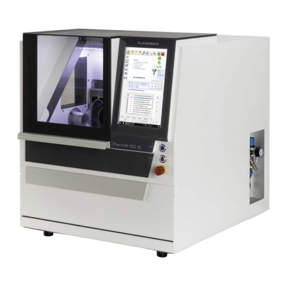
6 Milling unit 6 Milling unit 6.1 Front view 1. Lid 2. Access door for coolant tank 3. Milling unit foot 4. Operating keys 5. Touch screen User's manual Planmeca PlanMill 50 S... -
Page 30: Lid
The milling unit lid must be locked during milling. If the lid is open the milling cannot be started. After milling the lid is locked until all axes and the spindle have stopped To close the lid pull downwards (1) and then towards yourself (2). Planmeca PlanMill 50 S User's manual... -
Page 31: Milling Unit Controls
6 Milling unit 6.1.2 Milling unit controls 1. Touch screen control panel 2. EMERGENCY STOP switch 3. Lid button 4. Power button User's manual Planmeca PlanMill 50 S... -
Page 32: Side View
6.2 Side view 1. Side window 2. Type plate 3. Connection panel 6.3 Rear view 1. Earthing connection, housing rear wall 2. Connection for suction hose of the extraction system 3. Housing fan with integrated filter Planmeca PlanMill 50 S User's manual... -
Page 33: Connection Panel With Maintenance Unit
6. Control line for 7. Network connection 8. USB-B connection cold units - connection extraction system (sub- (RJ-45) cable D connection) 9. Drainage valve on 10. Separation tank 11. Additional the separation tank compressed air outlet (blank) User's manual Planmeca PlanMill 50 S... -
Page 34: Tool Magazine (Direct Changer)
The appropriate tools for this milling unit can be found in section "Milling tools" on page 21 and ordered from your local dealer. Planmeca PlanMill 50 S User's manual... -
Page 35: Cooling Liquid System
6.6 Cooling liquid system The cooling liquid system is only installed with milling units of type Planmeca PlanMill 50 S and is optimally tailored to the milling unit in the factory. Only use approved cooling liquid from Planmeca, because this is optimally tailored to the requirements of the milling unit and guarantees a seamless processing sequence. -
Page 36: Coolant Tank
6 Milling unit 6.6.1 Coolant tank The capacity of the Planmeca PlanMill 50 S milling unit’s coolant tank is 1.8 litres. The tank consists of sump, lid, filter, and screen insert. The filter and screen insert filter milling dust from the used cooling liquid. Clean the filter and screen insert regularly. -
Page 37: Axis Arrangement
A, B, C: generally the axis address letter for swivelling or pivoting axes. 6.7.2 Assignment of movement axes With systems of type Planmeca PlanMill 50 S: • X axis = lifting axis (+X down; -X up) •... -
Page 38: Adapters
7 Adapters 7 Adapters 7.1 Glass ceramic adapter 7.1.1 Attaching glass ceramic adapter 1. Detach the current adapter by removing the six attachment screws. Planmeca PlanMill 50 S User's manual... - Page 39 For attaching the glass ceramic adapter you’ll need an Allen key and four screws. 2. Place the adapter on the left side of the adapter. 3. Insert the screws in the screw holes and tighten using an Allen key. User's manual Planmeca PlanMill 50 S...
-
Page 40: Adapters For Premilled Abutments
Pins for calibrating adapters can be ordered from your local premilled blank supplier. The calibrating file for milling test pins is available from your local dealer and C:\NC_Daten\Planmeca Plan Mill 50 after installing can be found from folder S \Adapter Calibration . 7.2.1 DESS adapter Planmeca PlanMill 50 S User's manual... - Page 41 7 Adapters 7.2.1.1 General cleanliness and handling The adapter has to be calibrated in Planmeca PlanMill 50 S milling units before the first use to ensure an optimal positioning of the DESS system. Therefore the following aspects must be considered: •...
- Page 42 The test pins have to be clean and free of burrs for measuring Measurements • width (X-axis) (1) • length (Y-axis) (2) • height (Z-axis) (3) • width control measurement / only Pos 2 (4) • customer: • milling unit type: • serial number: Planmeca PlanMill 50 S User's manual...
-
Page 43: Medentika Adapter
7.2.2 Medentika adapter 7.2.2.1 General cleanliness and handling The adapter has to be calibrated in Planmeca PlanMill 50 S milling units before the first use to ensure an optimal positioning of the Medentika system. Therefore the following aspects must be considered: •... - Page 44 (2 + 5), pushed in to the limit, and firmly clamped with the clamping screw by using a torque wrench. Check that both test pins are attached directly without a gap to the supporting surface. Planmeca PlanMill 50 S User's manual...
- Page 45 The test pins are milled directly on the milling unit with the scripted test program available from your local dealer. A 2 mm metal tool (T2) is required for the milling process. User's manual Planmeca PlanMill 50 S...
- Page 46 7.2.2.4 Calculation and data transfer The offset values for the Planmeca PlanCAM software are determined after the measurement results are entered into the calculation program. Please contact the local dealer of your Planmeca PlanCAM software to implement the offset data.
-
Page 47: Nt-Trading Adapters
7.2.3 Nt-trading adapters 7.2.3.1 General cleanliness and handling To ensure an optimal positioning of the nt-trading system, the adapter has to be calibrated in Planmeca PlanMill 50 S milling units before the first use. Therefore the following aspects must be considered: •... - Page 48 The test pins have to be clean and free of burrs for measuring • width (X-axis) (1) • length (Y-axis) (2) • height (Z-axis) (3) • width control measurement / only Pos 2 (4) Planmeca PlanMill 50 S User's manual...
- Page 49 The offset values for the Planmeca PlanCAM software are determined after the measurement results are entered into the calculation program. • Please contact the local dealer of your Planmeca PlanCAM software to implement the offset data. User's manual Planmeca PlanMill 50 S...
-
Page 50: Operating Milling Unit
> shut down) 3. Now switch off the main switch on the milling unit’s connection panel 4. If necessary, also switch off additional accessories (e.g. extraction system) 5. If necessary, perform cleaning or maintenance work. Planmeca PlanMill 50 S User's manual... -
Page 51: Procedure During Operation
5. Start the referencing of the unit when prompted by the control software. 8.6 Using unit controls The Planmeca PlanMill 50 S is equipped with a touch screen control panel which is used for navigation and entering data. The control buttons are located on the right side of the unit. -
Page 52: Touch Screen Control Panel
Pressing the power button switches on the milling unit’s power electronics. It is only possible to switch on the power electronics if all safety-relevant milling unit equipment is correctly set, e.g. emergency stop switch disengaged. Planmeca PlanMill 50 S User's manual... - Page 53 NOTE IMPORTANT INFORMATION! After pressing the EMERGENCY STOP switch, before disengaging the EMERGENCY STOP switch, make sure that all faults have been remedied. Turn the EMERGENCY STOP switch to the right to disengage it. User's manual Planmeca PlanMill 50 S...
-
Page 54: Processing Modes
8.7.1 Dry processing NOTE Extraction systems from Planmeca are only suitable for dry dust! The extraction systems supplied by Planmeca are intended to vacuum dry milling dust only. Do not vacuum cooling liquid residue with the extraction systems supplied. This can lead to serious damage and even destruction of the extraction system. - Page 55 Furthermore, the dust that is not extracted may damage the milling unit and result in an increased risk of fire. The connection and operation of an extraction system approved by Planmeca is therefore required for the dry processing of materials.
-
Page 56: Wet Processing
1. Thoroughly clean the milling unit interior, the filter fleece chips and dry milling dust (wear protective gloves and safety goggles throughout!). 2. Remove the suction funnel and fit the protective cap on the suction port. 3. Remove the cover from the drainage hole. Planmeca PlanMill 50 S User's manual... -
Page 57: Modes Of Operation
11. Close the access door to the coolant tank, see step 4. 12. Start the milling with the coolant system switched on and without an extraction system. 8.8 Modes of operation The unit can be operated in three modes. User's manual Planmeca PlanMill 50 S... -
Page 58: Automatic Mode
No program start can take place in this milling unit state 8.8.3 Expanded set-up mode Expanded set-up is only accessible to authorised and trained specialist personnel (service personnel) of Planmeca. Access to this mode is protected by password. 8.9 Inserting workpiece 1. -
Page 59: Removing Workpiece
11. Check the secure seating of the workpiece. 8.10 Removing workpiece 1. Drive the unit to the blank change position by touching this button. 2. Stop all drives and the milling spindle. 3. Open the lid by pressing the lid button. User's manual Planmeca PlanMill 50 S... -
Page 60: Registering Tools In Control Software
8. Tighten the clamping screws of the clamping ring until hand-tight. 8.11 Registering tools in control software 1. Start Remote DENTAL by double-clicking the PlanMill 50 S icon on the desktop. 2. Click the green Confirm button to start the automatic reference run. - Page 61 4. Press the Edit tool field button. 5. In the appearing window, click the tool registration button. 6. Click the tool you will install inside the magazine and confirm your choice by clicking the green Confirm button. User's manual Planmeca PlanMill 50 S...
-
Page 62: Loading Tool Magazine
NOTE The list of approved tools can be found in section "Milling tools" on page 21. Only use milling tools from Planmeca. The milling tools from Planmeca are ready-ringed in the correct projecting length and are available from the local dealer. -
Page 63: Changing Tools
If, during the tool change, it is unclear which tool is presently in the collet chuck, the following definition window will be displayed on the screen of the control PC. User's manual Planmeca PlanMill 50 S... -
Page 64: Replacing Broken Milling Cutters
NOTE After replacing a defective tool: If the attempt to use a defective tool results in a milling process being interrupted, the process must be restarted after the defective tool is replaced! Planmeca PlanMill 50 S User's manual... -
Page 65: Before Milling
8.16 Process description The templates for components to be milled are transferred as an STL file to the Planmeca PlanCAM software. The components are positioned in a blank in the Planmeca PlanCAM. Subsequently, settings such as process speed, insertion depth of the milling cutter, milling sequence and scaling are automatically specified for further processing. -
Page 66: Dry Milling
(see section "Touch screen commands" on page 64). 6. Start the milling process. 8.18.1 Dry milling NOTE Always use the suction system for dry milling. 1. Open the milling chamber lid. 2. Remove the protective cap from the extraction nozzle. Planmeca PlanMill 50 S User's manual... -
Page 67: Wet Milling
2. Remove the extraction funnel. 3. Close the extraction nozzle by placing the protective cap onto it. 4. Start the milling process (for instructions see both "Wet processing" on page 50 and "Milling" on page 59). User's manual Planmeca PlanMill 50 S... -
Page 68: Switching Between Wet And Dry Milling
The extraction unit provided by Planmeca is intended solely for the extraction of DRY milling dust. Do not extract any coolant with the extractor provided by Planmeca. This may lead to damage or even destruction of the extraction unit. 8.19 Switching off the unit 1. -
Page 69: Control Software
9 Control software 9 Control software 9.1 Starting software To start the control software, double-click this icon on the desktop. User's manual Planmeca PlanMill 50 S... -
Page 70: User Interface
PC software. 9.3 Touch screen commands In the upper area of the overview screen is a function bar with integrated function buttons. The functions of the individual buttons are explained in the following section. Planmeca PlanMill 50 S User's manual... - Page 71 Opens a new window, see the figure below this table. In this window it is possible to open stored milling files. The folder Planmeca PlanMill 50 S is opened by default. This folder contains the sub- folders archive and calibration body, as well as the milling files stored in this folder by the function transfer milling files (see section "Process...
- Page 72 Purging on / off Manual switch on and off of the air nozzle. During automatic operation, switching on and off takes place automatically. Planmeca PlanMill 50 S User's manual...
-
Page 73: Tool Fields
To enable correct access to the tools, all tools located at the tool positions must be represented on the software interface. Only this way is it guaranteed that the milling unit uses the right tool. User's manual Planmeca PlanMill 50 S... - Page 74 Navigation arrow (one For navigating upwards through the tool list in single step up) steps. Navigation arrow (one For navigating down through the tool list in single step down) steps. Planmeca PlanMill 50 S User's manual...
- Page 75 Signals that the tool must be measured. Warning symbol Signals that the tool is broken or lies outside the defined tool length, after measuring. Tool life elapsed Signals that the tool life has elapsed and it must be replaced. User's manual Planmeca PlanMill 50 S...
- Page 76 3. Information field 4. Tool list Shows the type of the selected tool. Shows which tool is presently located in which tool position. The symbols provide information on the condition of the respective tool. Planmeca PlanMill 50 S User's manual...
-
Page 77: Edit Tool Field
Maximum tool life (tool It is possible to change the maximum service life of a service life) tool here. Planmeca specifies a suitable tool service life. This service life is based on many years of experience and should not be changed. However, the service life can be specifically adjusted here under your own responsibility. - Page 78 Attention symbol Signals that the tool must be measured. Tool length error Indicates a tool length error. In this case, the tool length is below or above the predefined minimum value. Planmeca PlanMill 50 S User's manual...
-
Page 79: Registering Tool In Software
Navigation arrow (one For navigating upwards through the tool list in single step up) steps. Navigation arrow (one For navigating down through the tool list in single step down) steps. User's manual Planmeca PlanMill 50 S... -
Page 80: Information Bars
Shows the current override value setting. When the control software is started, the override value is set to 100% as standard. Progress indicator Shows the progress of the milling program started as a percentage. Planmeca PlanMill 50 S User's manual... -
Page 81: Status Indicators
3. Temperature sensor 4. Displays information about the current used tool in the spindle: tool position, tool type, tool Displays the actual temperature inside the unit. service life and faults that arise. User's manual Planmeca PlanMill 50 S... -
Page 82: Service, Maintenance And Cleaning
Cleanliness increases the service life of the individual components and prevents malfunctions. Therefore clean the milling unit regularly with a hand brush, paintbrush or vacuum cleaner. Ensure that no dirt penetrates the milling unit mechanism. Planmeca PlanMill 50 S User's manual... -
Page 83: Electrical System
Risk of injury due to the use of incorrect replacement parts! The use of incorrect or faulty replacement parts brings with it extreme danger for personnel. This can result in damage, malfunctions or a total failure of the milling unit. User's manual Planmeca PlanMill 50 S... -
Page 84: General Cleanliness
Planmeca recommends the use of disposable towels for cleaning away cooling liquid residues inside the milling unit. The extraction unit supplied by Planmeca is only to be used for DRY milling dust. The extraction of coolant residues with the Planmeca extraction unit is not permitted and will damage the extraction unit. -
Page 85: Extraction Systems
Extraction systems supplied by Planmeca serve exclusively to vacuum dry milling dust. It is prohibited to vacuum cooling liquid residues with the extraction systems supplied by Planmeca, and this leads to damage and even destruction of the extraction system! Extraction systems from Planmeca must be cleaned and maintained regularly. - Page 86 10 Service, maintenance and cleaning NOTE Never spray with spray oils, liquids or compressed air directly onto the centrifugal disc of the spindle nose because moisture or dirt can penetrate right to the bearing. Planmeca PlanMill 50 S User's manual...
-
Page 87: Preventive Maintenance
Use only the manufacturer’s original replacement parts or replacement parts authorised by the manufacturer. • In case of doubt contact the local dealer. NOTE The use of unapproved replacement parts will void the manufacturer’s warranty. User's manual Planmeca PlanMill 50 S... -
Page 88: Maintenance Instructions
The following measures are recommended: 1. Avoid long and intensive contact with the skin. 2. Ensure that the skin is thoroughly cleaned after work and before breaks. 3. Preventive skin protection using skin protection creams is recommended. Planmeca PlanMill 50 S User's manual... - Page 89 8. If you are unable to screw the collet chuck in by hand to the stop, use the turning piece (3) Service position. 9. Exit the The spindle is now ready for operation. User's manual Planmeca PlanMill 50 S...
-
Page 90: Safety Interlocking System
You can order new filters from the local dealer. 11.3.4 Cooling liquids Cooling liquids must be used in accordance with the manufacturer's instructions. It is essential to strictly observe the data sheets and safety Planmeca PlanMill 50 S User's manual... -
Page 91: Water Separator
The guide rails and drive shafts are provided with long-term lubrication and are maintenance free. If necessary they will be re-lubricated during maintenance by qualified Planmeca personnel. 11.3.7 Coolant tank The following steps must be performed before each wet milling: 1. - Page 92 1. Open the coolant tank access door by pulling the two upper corners of the access door to release the locking mechanism. 2. Using a finger push the feed line and the float upwards until they reach the end. Planmeca PlanMill 50 S User's manual...
-
Page 93: Maintenance Plan
11.4.2 Daily • Check the water separator and empty if necessary 11.4.3 Weekly or after tool breakage • Remove the collet chuck • Clean the collet chuck • Check the collet chuck for damage User's manual Planmeca PlanMill 50 S... -
Page 94: Calibrating Milling System
3. Turn the workpiece holder to horizontal position (Special position 1) by pressing the approach to special position 1 button: 4. Push Cover button in the front side of the milling unit and open the lid. Planmeca PlanMill 50 S User's manual... - Page 95 11 Preventive maintenance 5. Loosen the locking screws on the workpiece holder’s clamping ring. 6. Remove the clamping ring. User's manual Planmeca PlanMill 50 S...
-
Page 96: Milling Zero Point And B-Axis Calibration Body
1. Attach work piece, as described in section "Attaching workpiece" on page 88, if not yet attached. 2. Switch on the suction. 3. On the desktop you will find a Service shortcut. Open the folder by double clicking the Service icon. Planmeca PlanMill 50 S User's manual... - Page 97 4. Inside the Service folder you will find some shortcuts to different service layers and service tools. 5. Double-click the TKZeroPoint option. 6. In the appearing Select the required calibration type window, click Zero- Point-and-B- Axis-Calibration button. User's manual Planmeca PlanMill 50 S...
- Page 98 11 Preventive maintenance 7. Select PlanMill 50 S from the Select the used machine drop-down menu. As instructed in under the 2. Mill both calibration bodies phase, do the following before continuing this dialog: 1. Start Remote DENTAL by double-clicking the PlanMill 50 S icon on the desktop.
-
Page 99: Measuring Zero Point And B-Axis Calibration Body
11 Preventive maintenance NOTE Milling-tool T11 (2.5mm/RADIUS PMMA/WAX) must be available. For more information, see section "Registering tools in control Planmeca PlanMill 50 S user's software" on page 54 and the manual . 5. Start the milling process, click the START icon: Milling unit starts the calibration body milling. -
Page 100: Calibrating Zero Point And B-Axis
The results are needed during the next steps. 11.5.4 Calibrating zero point and B-axis 1. In the TK-Zero-Point dialog select [WPZero] from the drop-down menu in the 3.Select the right Zero-Point section. Planmeca PlanMill 50 S User's manual... -
Page 101: Annual Maintenance
7. Repeat the process until the values are within tolerance. 11.6 Annual maintenance The unit should be serviced once a year by personnel authorised by Planmeca. This ensures a long service life and reliable operation. User's manual Planmeca PlanMill 50 S... -
Page 102: Troubleshooting
WARNING Rotating or linearly moving parts can cause serious injuries. Switch off all of the machine’s moving parts before starting troubleshooting on moving parts and wait until they have all come to a standstill. Planmeca PlanMill 50 S User's manual... -
Page 103: Improper Troubleshooting
• Check mains plug • Check power socket strip Main switch is not Turn on the main User turned on switch Fuse triggered/ Disconnect power plug, Electrician defective check fuse User's manual Planmeca PlanMill 50 S... - Page 104 Protective hood Close protective hood User be switched on interlocking not closed Protective hood not Close protective hood User closed correctly Emergency stop not Release the User released emergency stop Planmeca PlanMill 50 S User's manual...
- Page 105 Solution Contact personnel Power button not pressed Press the power button User Machine switched off Switch the machine on User Possible cause Solution Contact personnel Emergency stop not released Release the emergency stop User User's manual Planmeca PlanMill 50 S...
- Page 106 12 Troubleshooting Possible cause Solution Contact personnel Protective hood not closed Close the protective hood User Planmeca PlanMill 50 S User's manual...
- Page 107 Possible cause Solution Contact personnel Blank change position The machine drives to the blank User change position Possible cause Solution Contact personnel Home position The machine drives to the User home position User's manual Planmeca PlanMill 50 S...
- Page 108 The machine must be User referenced Confirm the start of the reference run by clicking on the button Possible cause Solution Contact personnel Reference run required The machine must be User referenced Start the reference run manually Planmeca PlanMill 50 S User's manual...
- Page 109 12 Troubleshooting Possible cause Solution Contact personnel Error when measuring the Check the tool in use for User length of the tool damage and replace if necessary User's manual Planmeca PlanMill 50 S...
- Page 110 Check the connection between User the control PC and machine Press the power button User Switch the machine on User Possible cause Solution Contact personnel Cancellation by user Start the desired action again User Planmeca PlanMill 50 S User's manual...
-
Page 111: Troubleshooting Tasks
Axis driven into end switch Drive the axis out of the end User switch 12.3 Troubleshooting tasks 12.3.1 Deactivating emergency stop 1. Determine and eliminate the source of the malfunction. 2. Release the emergency stop switch by turning. User's manual Planmeca PlanMill 50 S... -
Page 112: Replacing Fuses
5. Make sure that the replacement fuse is of the correct rating. 6. Insert the new fuse. 7. Close the fuse cover. 8. Connect the machine to the power supply. 9. Switch the machine on. Planmeca PlanMill 50 S User's manual... -
Page 113: Packaging And Storage
Do not exceed the load limit. Preferably store packages marked with this symbol in the uppermost position. This way up During transport and storage the arrow must point upwards. Do not tip, roll or lean the package. User's manual Planmeca PlanMill 50 S... -
Page 114: Transport
2. Insert the forks far enough that they protrude from the opposite side. 3. The package being transported must be securely fixed. 4. Check to ensure that pallets with an offset centre of gravity cannot tip. Planmeca PlanMill 50 S User's manual... - Page 115 14 Transport 5. Lift the pallet and item to be transported and commence transport. User's manual Planmeca PlanMill 50 S...
-
Page 116: Disassembly And Disposal
Sort all remaining parts according to their material properties WARNING Risk to the environment due to incorrect disposal! Incorrect disposal can pose a risk to the environment. • Use reputable, authorised companies to dispose of electrical, electronic components, liquids and other excipients Planmeca PlanMill 50 S User's manual... -
Page 117: Collection
15.3.2 Return and collection systems The Planmeca PlanMill 50 S may not be disposed of with household waste. 15.3.3 Disposal symbols All electrical and electronic equipment is marked with these symbols and, in accordance with the EU Directive, must not be disposed of with household waste. -
Page 118: Customer Information
If damage that falls under warranty coverage occurs to the product during the warranty period, Planmeca have the sole obligation and your only claim is the repair or replacement of the Planmeca product. -
Page 119: Technical Specifications
17 Technical specifications 17 Technical specifications Name: Planmeca PlanMill 50 S Planmeca Asentajankatu 6, 00880 Helsinki FINLAND Tel.: +358 20 7795 500 http://www.planmeca.com 17.1 Milling unit Type of drive High torque stepper motor Control Stepper motor controller IME 482 Milling chamber lid... -
Page 120: Connected Loads
Connection: Plug-in nipple NW 7.2 mm (quick connection) Air purity Solid contaminants class 3 – degree of filtration better than 5μm for solids Water content class 4 – maximum pressure dew point +3 °C (37 °F) Planmeca PlanMill 50 S User's manual... -
Page 121: Device Plate
17 Technical specifications Total oil content class 3 – maximal oil content 1mg/m3 Noise level Sound pressure level (milling of plastic): <70 dB(A) 17.4 Device plate User's manual Planmeca PlanMill 50 S... -
Page 122: Appendix A: Suction Unit (Optional)
CAUTION When changing used filters always wear mask, safety glasses and gloves. A.1.4 Warning and information labels The following figures show the labels and symbols and list their location on the unit. Planmeca PlanMill 50 S User's manual... - Page 123 Appendix A: Suction unit (optional) Inside filter door (at top): Top left of rear panel: Rear of unit, next to power connection: Above motor cooling on rear of unit: Top left of front door: User's manual Planmeca PlanMill 50 S...
-
Page 124: Installation
Do not block or cover any louvers or cooling holes on the unit as this severely restricts air flow and may cause damage to the unit. CAUTION Under no circumstances should the exhaust outlet/s be covered as this will restrict the airflow and cause overheating. Planmeca PlanMill 50 S User's manual... -
Page 125: Filter Blocked Signal
Do not block or cover the cooling vents on the unit, as this severely restricts airflow and may cause damage to the unit. CAUTION This unit is over 18 kg in weight and should only be lifted with suitable lifting equipment. User's manual Planmeca PlanMill 50 S... -
Page 126: Operation
A.4 Maintenance User maintenance is limited to cleaning the unit and replacing the filters with new. Only Planmeca trained maintenance technicians are authorised to carry out component testing and replacement. Unauthorised work or the use of unauthorised replacement filters may result in a potentially dangerous situation and/or damage to the extractor unit, and will invalidate the manufacturer’s warranty. -
Page 127: Replacing Filters
2. Remove the pre filter by lowering the supporting plate and replace with a new pre filter. 3. Push the supporting plate back up so it clips in place, close and fasten filter compartment latches. 4. Reconnect the electrical supply. User's manual Planmeca PlanMill 50 S... -
Page 128: Consumable Spares
* European waste catalogue A.5 Troubleshooting In the unlikely event of a problem with your extractor please contact your local representative or: Planmeca Asentajankatu 6 FIN-00880 Helsinki FINLAND A.6 Technical specifications Unit iVAC eco+ Planmeca PlanMill 50 S User's manual... - Page 129 95% @ 0.9µ Environmental operating range Temperature +5°C to +40°C (41°F to 104°F) Humidity Max 80% RH up to 31°C (88°F) to Max 50% RH at 40°C (104°F) Altitude Below 2000m (6562 ft) Pollution degree User's manual Planmeca PlanMill 50 S...
- Page 132 Planmeca Oy | Asentajankatu 6 | 00880 Helsinki | Finland tel. +358 20 7795 500 | fax +358 20 7795 555 | sales@planmeca.com | www.planmeca.com...
Need help?
Do you have a question about the PlanMill 50 S and is the answer not in the manual?
Questions and answers