Table of Contents
Advertisement
Quick Links
Advertisement
Table of Contents
Troubleshooting

Related Manuals for Planmeca PlanMill 60 S


Summary of Contents for Planmeca PlanMill 60 S
- Page 1 Planmeca PlanMill 60 S ® user's manual 30040852...
- Page 2 IEC 60364 - equipment is used according to the operating instructions. Planmeca pursues a policy of continual product development. Although every effort is made to produce up-to-date product documentation this publication should not be regarded as an infallible guide to current specifications. We reserve the right to make changes without prior notice.
-
Page 3: Table Of Contents
Radiation hazards.........................21 7.11 Dangers due to high temperatures....................21 System description........................... 22 Materials............................22 Coolant lubricant...........................22 Milling tools...........................23 Planmeca 60 S milling unit........................24 Front view............................. 24 9.1.1 Light indicators......................25 Side view............................26 Rear view............................27 9.3.1 Air pressure regulator....................27... - Page 4 Network drives......................49 13.5.11 Jobs..........................49 13.5.12 About this machine.......................50 13.5.13 Help and contact......................51 Planmeca PlanCAM software as part of milling process................52 Adapters..............................53 15.1 Attaching C-clamp adapter......................53 15.2 Glass ceramic adapter........................55 15.2.1 Attaching glass ceramic adapter.................. 55 15.3...
- Page 5 Technical information..........................91 21.1 Technical specifications........................91 21.2 Dimensions...........................94 21.3 Space requirements........................96 21.3.1 Operating space requirements..................96 21.3.2 Service and maintenance space requirements............97 Appendix A: Extraction system (optional)......................98 Safety instructions........................98 A.1.1 Symbols used.......................98 User's manual Planmeca PlanMill 60 S...
- Page 6 General safety requirements..................101 Operation............................102 A.3.1 Manual operation....................... 102 Maintenance..........................102 A.4.1 Cleaning unit......................102 A.4.2 Replacing filters......................102 A.4.3 Pre filter replacement....................103 A.4.4 Consumable spares....................103 A.4.5 Maintenance protocol....................104 A.4.6 Filter disposal......................104 Troubleshooting..........................104 Technical specifications......................104 Planmeca PlanMill 60 S User's manual...
-
Page 7: Introduction
This manual describes how to operate the Planmeca PlanMill 60 S milling unit. Despite every effort, it is not possible to fully exclude printing errors and mistakes. -
Page 8: Limitation Of Liability
You must therefore carefully read and precisely follow this user’s manual and the associated documents. The Planmeca PlanMill 60 S milling unit is intended for the production of dental indications and is specially developed to satisfy the requirements of the dental industry. -
Page 9: Accessories And Modifications
The general terms and conditions of Planmeca apply. 1.4 Accessories and modifications The attachment of accessories to the Planmeca PlanMill 60 S milling unit and any other modifications require the express permission of Planmeca. All attachments and modifications that may affect the operational safety of the milling unit are strictly prohibited and lead to the immediate voiding of CE-conformity and the manufacturer's guarantee. -
Page 10: Associated Documentation
Planmeca PlanMill 60 S installation manual For service personnel. Describes how to install the milling unit. NOTE The user's manual is also available on Planmeca's website: Material bank > Manuals > CAD/CAM > Dental milling. Planmeca PlanMill 60 S User's manual... -
Page 11: Training
3 Training 3 Training For hands-on user's training, please contact your local Planmeca dealer. User's manual Planmeca PlanMill 60 S... -
Page 12: Registering Your Product
4 Registering your product 4 Registering your product Please register your Planmeca device before you start using it. 1. Navigate to the registration website www.planmeca.com/register/ in your Internet browser. 2. Follow the instructions on the website. Planmeca PlanMill 60 S... -
Page 13: Annual Maintenance
5 Annual maintenance 5 Annual maintenance The unit should be serviced once a year by personnel authorised by Planmeca. This ensures a long service life and reliable operation. User's manual Planmeca PlanMill 60 S... -
Page 14: Symbols
Packages marked with this symbol contain fragile and sensitive goods. Treat the package with care and do not let it drop or expose it to shock or impact. Do not stack Never stack any objects on packages marked with this symbol. Planmeca PlanMill 60 S User's manual... -
Page 15: Disposal Symbols
During transport and storage the arrow must point upwards. Do not tip, roll or lean the package. 6.3 Disposal symbols All electrical and electronic equipment is marked with this symbol and, in accordance with the EU Directive, must not be disposed of with household waste. User's manual Planmeca PlanMill 60 S... -
Page 16: For Your Safety
You are at risk of serious injuries and even death if you remove or deactivate the safety equipment! • Do not dismantle or manipulate the safety device! • Check correct function of safety devices on a regular basis! • Have damaged safety equipment repaired immediately! Planmeca PlanMill 60 S User's manual... -
Page 17: Stopping Milling Unit Quickly
For service and maintenance work, the two rear cover panels enable access to the power electronics (only for Planmeca authorised service technicians). During operation, the protective door of the machine interior is locked and cannot be opened (cover status display does not light up). -
Page 18: Qualifications
Manufacturer (service technician) The manufacturer's specialist personnel are authorised to perform certain work exclusively. In order to carry out this work, contact your local Planmeca dealer. 7.3 Safety instructions for operation For safe handling of the machine, note the following points:... - Page 19 • Be aware of protruding tools! • Caution with sharp tools! • Never reach inside the machine until all components and tools are at a complete standstill! • Wear protective gloves and safety goggles! User's manual Planmeca PlanMill 60 S...
- Page 20 Loose tools or objects in the interior of the machine can block or be thrown around moving components of the machine. This can cause property damage! Before starting the machine, check the machine interior for loose and lying objects! Planmeca PlanMill 60 S User's manual...
-
Page 21: Residual Risks And Fundamental Dangers
Risk of injury due to cutting, impacts and crushing! • Hearing damage due to noise pollution! • Health hazard due to release of ozone! • Health damage due to dust / fine dust pollution! User's manual Planmeca PlanMill 60 S... -
Page 22: Reasonably Foreseeable Misuses
7.6.1 Danger due to electrical energy WARNING Risk of death due to electric shock! Contact with live parts or damage to insulation poses immediate danger to life and limb due to electric shock. Planmeca PlanMill 60 S User's manual... -
Page 23: Mechanical Hazards
For technical reasons, e.g. the processing spindle may run on! • Before starting lubrication, maintenance and servicing work in the hazard area, safely disconnect the energy and secure it against reconnection! User's manual Planmeca PlanMill 60 S... -
Page 24: Fire Hazard
When working with certain materials, fine milling/drilling dust may arise. This may be harmful to health or flammable and should - if necessary - be vacuumed with an extraction system approved by Planmeca, because this complies with the valid and applicable legal regulations! The milling unit user must ensure that: •... -
Page 25: Noise / Sound Emissions
The milling unit’s emissions sound pressure level is lower than or equal to 85 dB(A) when using the approved materials and tools. However noise peaks may arise with certain processing combinations, and the user must therefore ensure that: User's manual Planmeca PlanMill 60 S... -
Page 26: Freeing A Trapped Person
In case of fire: • Press the stop button on the milling unit front • Disconnect the power supply (fuse box) • Notify the fire brigade • Extinguish milling unit fire with CO2 fire extinguishers Planmeca PlanMill 60 S User's manual... -
Page 27: Radiation Hazards
Therefore ensure that surfaces have cooled to ambient temperature before commencing all work or activities. Tools, work pieces and chips may become very hot. Always wear heat-resistant work clothing and protective gloves during work! User's manual Planmeca PlanMill 60 S... -
Page 28: System Description
8 System description 8 System description Planmeca PlanMill 60 S is a milling unit intended for the production of dental indications and has been specially developed to satisfy the requirements of the dental industry. Planmeca PlanMill 60 S is not suitable for the application of conventional milling techniques. -
Page 29: Milling Tools
• Cooling liquid 1000ml (10036920) 8.3 Milling tools The tools approved by Planmeca for use in the Planmeca PlanMill 60 S milling unit are listed in the table below. WARNING Only use tools that are approved by Planmeca or that have been retrospectively approved. -
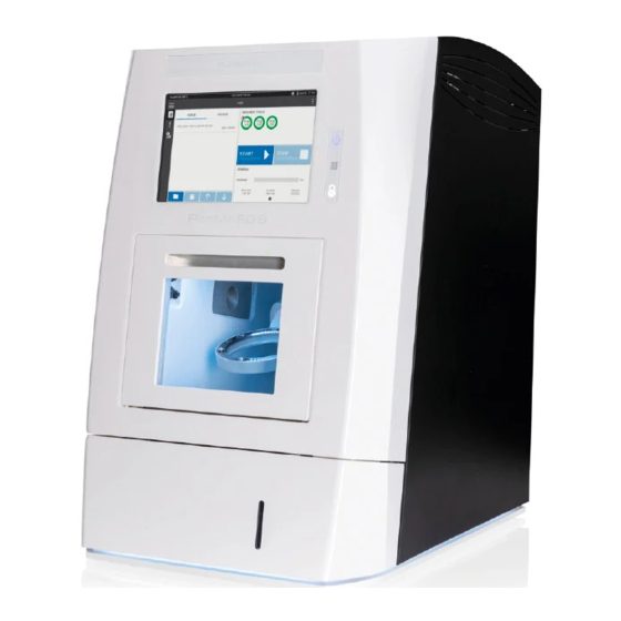
Page 30: Planmeca 60 S Milling Unit
9 Planmeca 60 S milling unit 9 Planmeca 60 S milling unit 9.1 Front view 1 Touch screen The milling unit is operated via the touch screen. Navigation and entry of data for the operating system and control software are done directly via the touch screen. -
Page 31: Light Indicators
9 Planmeca 60 S milling unit Operating keys 1 Power button - blue Pressing the power button switches on the machine's power electronics. It is only possible to switch on the power electronics if all safety-relevant electronic equipment is fully functional. -
Page 32: Side View
9 Planmeca 60 S milling unit 9.2 Side view 1 Ventilation slits 2 Air pressure regulator 3 Milling unit feet Planmeca PlanMill 60 S User's manual... -
Page 33: Rear View
9 Planmeca 60 S milling unit 9.3 Rear view 1 Ventilation slits 2 Suction port for the extraction system 3 Air pressure regulator 4 Ventilation fans 5 On/off switch 6 Connection panel 9.3.1 Air pressure regulator The air pressure regulator with a condensate container for the compressed air is located on the rear of the machine. - Page 34 9 Planmeca 60 S milling unit 1 Condensate container 2 Compressed air connection (plug-in nipple NW 7.2 (quick connection) 3 Condensate outlet (tightens/loosens manually) 4 Pressure display (bar) 5 Pressure regulator Planmeca PlanMill 60 S User's manual...
-
Page 35: Connection Panel
9 Planmeca 60 S milling unit 9.3.2 Connection panel 1 Connection for light indicators 2 Air connection for air pressure regulator 3 RJ-45 Network connection 4 USB-socket type A (USB connection) 5 Sub-D connection for the control line of the extraction system... -
Page 36: Processing Area
9 Planmeca 60 S milling unit 9.4 Processing area 1 Workspace lighting 2 Electronic connections for automatic calibration 3 Suction nozzles 4 Coolant lubricant runoff 5 Machining spindle 6 Ionizer seal 7 Ionizer 9.5 Workpiece holder with tool magazine The milling unit’s tool magazine contains a total of 10 tool positions for ready-ringed tools. -
Page 37: Coolant Lubricant System
1 Coolant lubricant tank 2 Front panel 9.6.1 Coolant lubricant tank The capacity of the Planmeca PlanMill 60 S milling unit’s coolant lubricant tank is 3 litres. The tank consists of several components, see below. The User's manual Planmeca PlanMill 60 S... -
Page 38: Coolant Lubricants
9.6.2 Coolant lubricants Only use coolant lubricants approved by Planmeca for material processing with a coolant lubricant system. The coolant lubricants used by Planmeca are optimally tailored to the requirements of the milling unit and guarantee a seamless processing sequence. To ensure intended use, storage and disposal of the coolant lubricant be sure to read the respective safety data sheet issued by the manufacturer. -
Page 39: Axis Arrangement
9 Planmeca 60 S milling unit 9.7 Axis arrangement 9.7.1 View of axis arrangement View from left View from front 9.7.2 Coordinate system The linear axes are labelled with the letters X, Y and Z. Rotary axes and swivel axes are generally labelled with the letters A, B, and... -
Page 40: Assignment Of Movement Axes
9 Planmeca 60 S milling unit 9.7.3 Assignment of movement axes Axis Designation Description Longitudinal axis +X towards the back -X towards the front Transverse axis +Y to the right -Y to the left Stroke axis +Z upwards -Z downwards... -
Page 41: Extraction System
The extraction unit provided by Planmeca is intended solely for the extraction of DRY milling dust. Do not extract any coolant lubricant with the extractor provided by Planmeca. This may lead to damage or even destruction of the extraction unit. -
Page 42: Dry Vs. Wet Milling Process
11 Dry vs. wet milling process 11 Dry vs. wet milling process The Planmeca 60 S milling unit handles both dry and wet milling. The wet milling process uses a coolant lubricant to remove excess material from the cutting tool and milling material. During dry processing, the material is processed without a coolant lubricant system, and instead, an extraction system is used to vacuum the dry miling dust. -
Page 43: Switching Milling Unit On/Off
3. Press the on/off switch on the rear of the milling unit to switch the unit off. The light on the switch goes off and the switch is in the 0 position. 4. Switch off the extraction system. User's manual Planmeca PlanMill 60 S... -
Page 44: Control Software
Requires Internet connection. Searches for updates for Smart Control Dental Studio software. • Disable fullscreen Disables full screen and allows to enter integrated PC running software. This menu item is password-protected only for Planmeca approved service technicians. Planmeca PlanMill 60 S User's manual... -
Page 45: Menu Selection
The milling files display shows the milling files that are in the queue to be milled next and the estimated milling process duration for each file. The milling process of a file in the queue is started by pressing the Start button. User's manual Planmeca PlanMill 60 S... -
Page 46: Options For Milling Files
The processing status display shows run times and percentage status for the currently ongoing milling file. 1 Percentage status of the current milling file 2 Start time of current milling file 3 Duration of the current milling file 4 Elapsed time of current milling file Planmeca PlanMill 60 S User's manual... -
Page 47: Machining Options
3 Remaining run time of the tool in hours and minutes 13.4 Tools menu Tools menu item contains information on the status and run time of the tools. In addition, you can edit the tools (tool stations). User's manual Planmeca PlanMill 60 S... -
Page 48: Overview Of Tool Stations And Assignment
(hours and minutes). The colour of the pie chart can be green (> 40 % run time left), yellow (10-40 % run time left) or red (< 10 % run time left). Planmeca PlanMill 60 S User's manual... -
Page 49: Edit Tool Stations
Reset to reset to the default zoom level. 13.4.2 Edit tool stations Tools > Edit tool stations menu you can edit the tool stations used in In the the milling process. Change the tool assigment for this tool station. User's manual Planmeca PlanMill 60 S... -
Page 50: Tool Information
The blank position is a position for loading the workpiece holder. The blank position is a position for loading the workpiece holder. The collet position is a position for cleaning the collet. Planmeca PlanMill 60 S User's manual... -
Page 51: General
Machine starts dry cleaning program using air and suction. • Execute wet cleaning Machine starts wet cleaning using coolant. • Execute spindle maintenace Machine drives spindle into a position that allows executing maintenance for spindle/collet. User's manual Planmeca PlanMill 60 S... -
Page 52: Calibration
Settings > Functions menu you can perform the following actions by In the pressing the toggle button: • switch on/off the coolant lubricant pump • switch on/off the suction • switch on/off the cleaning air • open/close the collet. Planmeca PlanMill 60 S User's manual... -
Page 53: Temperature
13 Control software 13.5.6 Temperature Settings > Temperature menu shows the following temperatures: • Current interior temperature • Minimum interior temperature • Maximum interior temperature User's manual Planmeca PlanMill 60 S... -
Page 54: Positions
German, and the available colour themes are light and dark. 13.5.9 Wi-fi NOTE We recommend that the milling unit is connected to the network via an Ethernet cable as it provides a more stable connection than wi-fi. Planmeca PlanMill 60 S User's manual... -
Page 55: Network Drives
• for how long is the milling job archived (default 30 days) • should deleted milling job also be deleted from CAM PC • activate/deactivate different types of holders User's manual Planmeca PlanMill 60 S... -
Page 56: About This Machine
Machine • Machine name • Model number • Manufacturing date • Serial number Computer • Device name • Version • Build number • Architecture • Language Application Planmeca PlanMill 60 S User's manual... -
Page 57: Help And Contact
Help and contact menu also shows details about the service situation as well as technical details, such as serial number, model number and application version of the milling unit. User's manual Planmeca PlanMill 60 S... -
Page 58: Planmeca Plancam Software As Part Of Milling Process
The templates for components to be milled are transferred from CAD design software (e.g. PlanCAD Premium) as an STL file to Planmeca PlanCAM software. The components are positioned in a blank in Planmeca PlanCAM. Subsequently, settings such as process speed, insertion depth of the milling cutter, milling sequence and scaling are automatically specified for further processing. -
Page 59: Adapters
2. Go to Settings > Blank position 0°. 3. When the cover status display lights up, open the protective door. 4. Remove the two bolts with the torque wrench included in the shipment. 5. Remove the workpiece holder. User's manual Planmeca PlanMill 60 S... - Page 60 6. Clean the mounting socket with a brush. 7. Clean the mounting plate of the C-clamp adapter with a brush. There is a guide hole on the C-clamp adater and a guide rod on the mounting socket. Planmeca PlanMill 60 S User's manual...
-
Page 61: Glass Ceramic Adapter
8.b. When both bolts are in place, apply the the torque in tightening them. 15.2 Glass ceramic adapter 15.2.1 Attaching glass ceramic adapter 1. Detach the current adapter by removing the six attachment screws. User's manual Planmeca PlanMill 60 S... - Page 62 3. Insert the screws in the screw holes and tighten using an Allen key. First, fasten the screws loosly, and when all screws are in place, tighten them firmly. The glass ceramic adapter does not require any calibration before milling. Planmeca PlanMill 60 S User's manual...
-
Page 63: Adapters For Premilled Abutments
55 . 15.3.1.1 General cleanliness and handling The adapter has to be calibrated in the Planmeca PlanMill 60 S milling unit before the first use to ensure an optimal positioning of the DESS system. Therefore the following aspects must be considered: •... - Page 64 1 - 6. • The test pins are milled directly on the milling unit with the scripted test program available from your local dealer. A 2mm metal tool (T2) is required for the milling process. Planmeca PlanMill 60 S User's manual...
- Page 65 The test pins have to be clean and free of burrs for measuring Measurements • width (X-axis) (1) • length (Y-axis) (2) • height (Z-axis) (3) • width control measurement / only Pos 2 (4) • customer: • milling unit type: • serial number: User's manual Planmeca PlanMill 60 S...
-
Page 66: Medentika Adapter
55. 15.3.2.1 General cleanliness and handling The adapter has to be calibrated in the Planmeca PlanMill 60 S milling unit before the first use to ensure an optimal positioning of the Medentika system. Therefore the following aspects must be considered:... - Page 67 (2 + 5), pushed in to the limit, and firmly clamped with the clamping screw by using a torque wrench. Check that both test pins are attached directly without a gap to the supporting surface. User's manual Planmeca PlanMill 60 S...
- Page 68 The test pins are milled directly on the milling unit with the scripted test program available from your local dealer. A 2 mm metal tool (T2) is required for the milling process. Planmeca PlanMill 60 S User's manual...
- Page 69 15.3.2.4 Calculation and data transfer The offset values for the Planmeca PlanCAM software are determined after the measurement results are entered into the calculation program. Please contact the local dealer of your Planmeca PlanCAM software to implement the offset data.
-
Page 70: Nt-Trading Adapters
15.3.3.1 General cleanliness and handling To ensure an optimal positioning of the nt-trading system, the adapter has to be calibrated in the Planmeca PlanMill 60 S milling unit before the first use. Therefore the following aspects must be considered: •... - Page 71 15.3.3.3 Measurement • The two test pins are unscrewed from the adapter • The test pins have to be clean and free of burrs for measuring • width (X-axis) (1) • length (Y-axis) (2) User's manual Planmeca PlanMill 60 S...
- Page 72 The offset values for the Planmeca PlanCAM software are determined after the measurement results are entered into the calculation program. • Please contact the local dealer of your Planmeca PlanCAM software to implement the offset data. Planmeca PlanMill 60 S...
-
Page 73: Operating Milling Unit
During a milling process the protective door to the milling area is locked and can only be opened when all axes and the machining spindle have come to a standstill. User's manual Planmeca PlanMill 60 S... -
Page 74: Inserting Workpiece/Blank
2. Press Blank position 0° to drive the milling unit to the blank change position. 3. When the cover status display lights up, open the protective door. 4. Loosen the clamping screws of the clamping ring (1) (do not remove) using a 3 mm Allen key. Planmeca PlanMill 60 S User's manual... -
Page 75: Removing Workpiece
Options menu. 1. Press Settings in the 2. Press Blank position 0° to drive the milling unit to the blank change position. 3. When the cover status display lights up, open the protective door. User's manual Planmeca PlanMill 60 S... - Page 76 4. Loosen the clamping screws of the clamping ring (1) (do not remove) using a 3 mm Allen key. 5. Remove the clamping ring by turning it in a clockwise direction to the right. 6. Remove the workpiece. 7. Close the protective door. Planmeca PlanMill 60 S User's manual...
-
Page 77: Loading Tool Magazine
Only use milling tools from Planmeca. The milling tools from Planmeca are ready-ringed in the correct projecting length and are available from your local Planmeca dealer. -
Page 78: Assigning Tools
Steps Tools menu item. 1. Press Tools to open the 2. Select a tool number to be picked up by the machining spindle. 3. Press Measure. 4. Press Yes to confirm your selection. Planmeca PlanMill 60 S User's manual... -
Page 79: Replacing Tools In Magazine
Make sure that all plug-in connections are securely seated • Check that the workpiece is secure so that it cannot become loose during processing • Check the ambient temperature; this should correspond with the information provided in the technical data User's manual Planmeca PlanMill 60 S... -
Page 80: Preparing For Dry Milling
Planmeca. CAUTION Extraction systems supplied or approved by Planmeca are only suitable for dry dust and are intended to vacuum dry milling dust only. Do not vacuum coolant lubricant residue with the extraction systems supplied. This can lead to serious damage and even destruction of the extraction system. -
Page 81: Preparing For Wet Milling
2. Plug the hose of the extraction system into the suction port (2). 3. If you are using another extraction system than that provided by Planmeca, check that the extraction system is correctly connected. What to do next Start the milling process with the extraction system switched on. See section "Starting milling process"... -
Page 82: Switching Between Wet And Dry Milling
Avoid any mixing of dry dust with the coolant lubricant as the dust / coolant lubricant mixture can lead to severe contamination of the unit. Planmeca PlanMill 60 S User's manual... -
Page 83: Starting Milling Process
The extraction unit provided by Planmeca is intended solely for the extraction of DRY milling dust. Do not extract any coolant lubricant with the extractor provided by Planmeca. This may lead to damage or even destruction of the extraction unit. -
Page 84: Cleaning And Maintenance
Cleaning and daily maintenance is to be performed by a trained milling unit user. Annual maintenance can only be performed by a Planmeca authorised service technician. Automatic cleaning programs can be used to make daily cleaning Cleaning and maintenance procedures easier. -
Page 85: Safety Instructions For Cleaning And Maintenance
The glass-ceramic / milling chips inside may be sharp-edged or pointed and could cause deep cuts or injuries. Always wear protective gloves and safety goggles when cleaning the coolant lubricant tank and filter. User's manual Planmeca PlanMill 60 S... -
Page 86: Suitable Cleaning Products
17.5 Protective door NOTE Never use abrasive cleaning products on the protective door. Only an approved glass cleaning product must be used. Clean the protective door daily so that the machining process can be monitored. Planmeca PlanMill 60 S User's manual... -
Page 87: Milling Chamber
(reduced centrifugal forces). • In order to guarantee concentricity, the clamping device must not be damaged. To check this, open the collet, remove the tool and check the collet for damage, corrosion or soiling (deposits). User's manual Planmeca PlanMill 60 S... -
Page 88: Collet
Long-term contact with chuck grease may cause irritation to the skin and/or dermatitis. Avoid long and intensive contact with the skin, and ensure that the skin is thoroughly cleaned after work and before breaks. The use of a skin protection cream is recommended. Planmeca PlanMill 60 S User's manual... -
Page 89: Cleaning Collet
Tighten the collet until it is hand-tight. 11. Use your thumb and index finger to grip the ring of the tool that was unclamped in step 5. Insert the tool into the machining spindle and close the collet. User's manual Planmeca PlanMill 60 S... -
Page 90: Guide Rails And Drive Shafts
The optional extraction systems supplied by Planmeca serve exclusively to vacuum dry milling dust. It is prohibited to vacuum coolant lubricant residues with the optional extraction systems supplied by Planmeca, and this leads to damage and even destruction of the extraction system! The optional extraction systems from Planmeca must be cleaned and maintained regularly. -
Page 91: Condensate Container
We recommend that milling units in multi-shift operation be subjected to semiannual maintenance and milling units in single-shift operation be subjected to annual maintenance of the milling unit by a Planmeca approved service technician. All mechanical components and machine parts are subject to increased (natural) wear. -
Page 92: Calibrating Milling Unit
Note the following issues before starting the calibration. • For calibration workpiece, use the Calibration disc (part number 10036901). The correct type of workpiece is available from your local Planmeca dealer. • An intact milling-tool T11/T13 (2.5mm/3.0mm/Zr PMMA/WAX) must be available and equipped to the tool magazine. - Page 93 18 Calibrating milling unit 4. Enter the measurement results for calibration body 12 in the left column. 5. Save the entries. User's manual Planmeca PlanMill 60 S...
-
Page 94: Troubleshooting
It is therefore essential to put the machine into a safe state before starting work. This work must be performed by Planmeca authorised service technicians. Before starting work, ensure that there is adequate free space for assembly. -
Page 95: Troubleshooting Table
Milling results do not Incorrect tool Check/correct the tool User match assignment in the tool assignment in the tool changer changer Workpiece zero point Mill calibrating bodies 3 User inaccurate or B-axis and 12 crooked User's manual Planmeca PlanMill 60 S... -
Page 96: Disposal
This product must NOT be disposed of with other waste. It is the user’s responsibility to dispose of their electrical and electronic waste equipment by handing it over to an approved reprocessor, or by returning it to Planmeca for reprocessing. For more information on where you can send your waste equipment for recycling, please contact your local city office or Planmeca. -
Page 97: Technical Information
Cooling lubricant tank 3.0 litres Maximum installation height 2000 metres (1.25 miles) above sea level Maximum setting angle A-axis: 30° / B-axis: 25° Monitor 10" touchscreen Machining spindle Specification Value Tool change Electric direct tool changer User's manual Planmeca PlanMill 60 S... - Page 98 Imprecision during processing can only be ruled out with an ambient temperature from +18 to +25°C. If your ambient temperatures are not within this range, we recommend an air conditioner. Contactyour local Planmeca dealer for this purpose. Requirement Specification...
- Page 99 1 mg / m Noise emission NOTE The noise pressure level may vary depending on the material and milling parameters. Specification Certificate Value Noise level Milling in plastic < 70 dB (A) Type plate User's manual Planmeca PlanMill 60 S...
-
Page 100: Dimensions
21 Technical information 21.2 Dimensions Front view Planmeca PlanMill 60 S User's manual... - Page 101 21 Technical information Side view User's manual Planmeca PlanMill 60 S...
-
Page 102: Space Requirements
If dry milling is used, the milling unit must be positioned for operation as shown in the figure below; distance of 1 meter (40 inches) in front, and 30 cm (12 inches) on other sides of the unit must be available as a minimum. Planmeca PlanMill 60 S User's manual... -
Page 103: Service And Maintenance Space Requirements
There must be a safety distance of 1 meter (40 inches) around the machine to guarantee an unobstructed area in the workplace, so that the unit is freely accessible from all sides during service and maintenance work. User's manual Planmeca PlanMill 60 S... -
Page 104: Appendix A: Extraction System (Optional)
CAUTION When changing used filters always wear mask, safety glasses and gloves. A.1.4 Warning and information labels The following figures show the labels and symbols and list their location on the unit. Planmeca PlanMill 60 S User's manual... - Page 105 Appendix A: Extraction system (optional) Inside filter door (at top): Top left of rear panel: Rear of unit, next to power connection: Above motor cooling on rear of unit: Top left of front door: User's manual Planmeca PlanMill 60 S...
-
Page 106: Installation
Do not block or cover any louvers or cooling holes on the unit as this severely restricts air flow and may cause damage to the unit. CAUTION Under no circumstances should the exhaust outlet/s be covered as this will restrict the airflow and cause overheating. Planmeca PlanMill 60 S User's manual... -
Page 107: Filter Blocked Signal
This unit is over 18 kg in weight and should only be lifted with suitable lifting equipment. CAUTION If this equipment is used in a manner not specified by the manufacturer, the protection provided by the equipment may be impaired. User's manual Planmeca PlanMill 60 S... -
Page 108: Operation
A.4 Maintenance User maintenance is limited to cleaning the unit and replacing the filters with new. Only Planmeca trained maintenance technicians are authorised to carry out component testing and replacement. Unauthorised work or the use of unauthorised replacement filters may result in a potentially dangerous situation and/or damage to the extractor unit, and will invalidate the manufacturer’s warranty. -
Page 109: Pre Filter Replacement
3. Push the supporting plate back up so it clips in place, close and fasten filter compartment latches. 4. Reconnect the electrical supply. A.4.4 Consumable spares Unit Part number Description iVAC eco+ 513002 0050 5 layer bag filter User's manual Planmeca PlanMill 60 S... -
Page 110: Maintenance Protocol
FIN-00880 Helsinki FINLAND A.6 Technical specifications Unit iVAC eco+ Capacity 260 m³/hr (9182 ft³/hr) Size H 750mm x D 460mm x W 440mm (30 x 18 x 17 in.) Weight 30 kg (66 lbs) Planmeca PlanMill 60 S User's manual... - Page 111 95% @ 0.9µ Environmental operating range Temperature +5°C to +40°C (41°F to 104°F) Humidity Max 80% RH up to 31°C (88°F) to Max 50% RH at 40°C (104°F) Altitude Below 2000m (6562 ft) Pollution degree User's manual Planmeca PlanMill 60 S...
- Page 114 Planmeca Oy | Asentajankatu 6 | 00880 Helsinki | Finland tel. +358 20 7795 500 | fax +358 20 7795 555 | sales@planmeca.com | www.planmeca.com...
Need help?
Do you have a question about the PlanMill 60 S and is the answer not in the manual?
Questions and answers