Planmeca ProMax 3D S User Manual
Dental x-ray unit, 3d imaging
Hide thumbs
Also See for ProMax 3D S:
- User manual (110 pages) ,
- Technical manual (378 pages) ,
- User manual (90 pages)
Table of Contents
Advertisement
Advertisement
Table of Contents

Related Manuals for Planmeca ProMax 3D S


Summary of Contents for Planmeca ProMax 3D S
- Page 1 Planmeca ProMax 3D s / 3D user's manual 3D imaging...
-
Page 3: Table Of Contents
12.5 Taking a scout image or 2D views (Lat-PA, Lat or PA) ..........61 3D EXPOSURE IN “LARGE VIEW 2 VERTICAL” ........63 13.1 Patient positioning with target movement 3 cm ............64 13.2 Patient positioning with target movement 6 cm ............65 Planmeca ProMax 3D s / 3D 1 User’s Manual (3D) - Page 4 IEC 60364 - equipment is used according to the operating instructions Planmeca pursues a policy of continual product development. Although every effort is made to produce up-to-date product documentation this publication should not be regarded as an infallible guide to current specifications. We reserve the right to make changes without prior notice.
-
Page 5: Introduction
You need a PC with the Planmeca Romexis program in order to save, view and modify the images. NOTE The X-ray unit may be used by health care professionals only. -
Page 6: Associated Documentation
The Romexis package contains the following manuals: • User’s Manual, Original English publication: 10014593 • Installation Manual, Original English publication: 10014600 NOTE The latest versions of the User’s Manuals are available on Planmeca’s website. 2 Planmeca ProMax 3D s / 3D User’s Manual (3D) -
Page 7: Symbols On Product Labels
(Standard IEC 60601-1) Type B applied part (Standard IEC 60601-1) Separate collection for electrical and electronic equipment (Directive 2002/96/EC WEEE) Alternating current (Standard IEC 60417) Electrostatic sensitive device (Standard IEC 60417) Planmeca ProMax 3D s / 3D 3 User’s Manual (3D) -
Page 8: Safety Precautions
CAUTION The patient positioning lights are laser lights. Do not stare into the laser beam. CAUTION Do not drop the sensor. Planmeca limited warranty does not cover damage which is due to misuse, e.g. dropping the sensor, neglect, or any cause other than ordinary use. - Page 9 NOTE Contact your service technician if you have taken an exposure but the image does not appear in the Planmeca Romexis program. The last ten images can be manually imported into Romexis. NOTE Never place or hang any objects on any part of the X- ray unit.
- Page 10 NOTE Patients are not allowed to hang on the patient handles. NOTE FOR PROFACE SENSOR: Do not touch the glass windows. Fingerprints or other stains on the glass surface destroy image quality. ProFace sensor 6 Planmeca ProMax 3D s / 3D User’s Manual (3D)
-
Page 11: Main Parts
MAIN PARTS MAIN PARTS General view of system Ethernet 1 X-ray unit 2 3D reconstruction PC 3 Planmeca Romexis program Planmeca ProMax 3D s / 3D 7 User’s Manual (3D) -
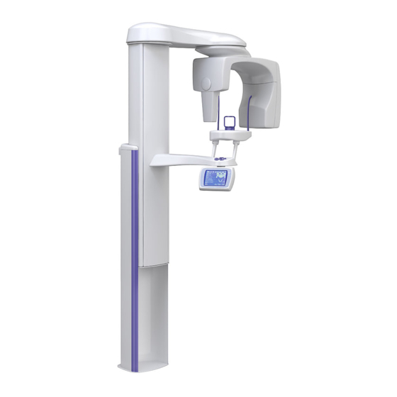
Page 12: General View Of X-Ray Unit
MAIN PARTS General view of X-ray unit Head support C-arm Sensor Patient support table Patient handles Patient positioning controls Telescopic column Control panel Stationary column Chair (included in delivery) 8 Planmeca ProMax 3D s / 3D User’s Manual (3D) -
Page 13: Sensors
Sensors 1 3D sensor for Planmeca ProMax 3D s 2 3D sensor for Planmeca ProMax 3D Classic 3 ProFace sensor for Planmeca ProMax 3D s and Planmeca ProMax 3D Classic Planmeca ProMax 3D s / 3D 9 User’s Manual (3D) -
Page 14: Patient Supports
Patient supports 5.4.1 Head supports (A or B) 1 Adjustable head support 1. Head band 25 2 Temple pads for children 2. Support bars 3 Fastening straps 4 Support bars 10 Planmeca ProMax 3D s / 3D User’s Manual (3D) - Page 15 MAIN PARTS 5.4.2 Chin supports 1 Chin cup 2 Chin support 3 Adjustable adapter Planmeca ProMax 3D s / 3D 11 User’s Manual (3D)
-
Page 16: Exposure Switch
C-arm will stop moving and a help message will appear on the control panel display. Guide the patient away from the X-ray unit. Then clear the help message by touching OK. 12 Planmeca ProMax 3D s / 3D User’s Manual (3D) -
Page 17: Emergency Stop Button
The X-ray unit is then ready for use. On / off switch NOTE To prolong the lifetime of the X-ray unit, always switch the unit off when it is not in active use. Planmeca ProMax 3D s / 3D 13 User’s Manual (3D) -
Page 18: Programs
3D, 3D ProFace or Horizontal and vertical Dimax segmenting Tomography Digital tomography Dimax Digital transtomography Cephalostat Scanning Ceph Dimax Planmeca ProCeph ProCeph Dynamic Exposure Panoramic DEC Dimax Control (DEC) Cephalometric DEC 14 Planmeca ProMax 3D s / 3D User’s Manual (3D) -
Page 19: Planmeca Promax 3D S
• Left premolar • Right premolar • Left molar • Right molar • Left ramus • Right ramus • Left TMJ • Right TMJ • Left ear • Right ear Planmeca ProMax 3D s / 3D 15 User’s Manual (3D) - Page 20 The 2 vertical maximum combined volume sizes are 50 x 110 mm and 50 x 130 mm for adults (depending on the selected vertical movement). 16 Planmeca ProMax 3D s / 3D User’s Manual (3D)
-
Page 21: Planmeca Promax 3D
Adult: 50 x 80 mm (ØxH) Volume height Child: 68 x 42 mm (ØxH) Child: 42 x 42 mm (ØxH) UPPER / LOWER Adult: 80 x 50 mm (ØxH) Adult: 50 x 50 mm (ØxH) Planmeca ProMax 3D s / 3D 17 User’s Manual (3D) - Page 22 • Left premolar • Right premolar • Left molar • Right molar • Left ramus • Right ramus • Left TMJ • Right TMJ • Left ear • Right ear 18 Planmeca ProMax 3D s / 3D User’s Manual (3D)
- Page 23 The maximum combined volume sizes are 80 x 110 mm and 80 x 130 mm for adults (depending on the selected vertical movement). Planmeca ProMax 3D s / 3D 19 User’s Manual (3D)
- Page 24 PROGRAMS 7.2.3 3D Model programs Preprogrammed target position Volume diameter Full Volume height Lower 20 Planmeca ProMax 3D s / 3D User’s Manual (3D)
-
Page 25: Control Panel
NOTE The exposure time indicated on the display before an exposure is taken is an estimated value. The real value is shown after the exposure. Variation in exposure time is caused by mA automation. Planmeca ProMax 3D s / 3D 21 User’s Manual (3D) -
Page 26: Selecting 3D Program
On the next display, select the 3D program you wish to use. Refer to section 7.1 “Planmeca ProMax 3D s” on page 15 to view the volume sizes available for each program type. 22 Planmeca ProMax 3D s / 3D... -
Page 27: Selecting Patient Size
The preset exposure values for the selected exposure program are shown in the quick buttons at the bottom of the display. Quick buttons NOTE Selecting kV and mA values manually will override the automatic quick button setting. Planmeca ProMax 3D s / 3D 23 User’s Manual (3D) -
Page 28: Changing Exposure Values For Quick Buttons
Selecting the smallest patient size will automatically change the jaw size setting to Narrow. Selecting any of the three patient sizes in the middle will automatically change the jaw size setting to Average. 24 Planmeca ProMax 3D s / 3D User’s Manual (3D) - Page 29 Volume Height field. If you select Lower or Upper only the selected half of the target area will be exposed, and selecting Full will produce a full size image of the whole target area. Upper Full Lower Planmeca ProMax 3D s / 3D 25 User’s Manual (3D)
- Page 30 The target area can also be selected by simply touching the jaw icon on the corresponding location. Refer to section 7.1 “Planmeca ProMax 3D s” on page 15 to view the preprogrammed target areas in each program. Confirm your selections and return to the main display by touching OK.
- Page 31 You can return to the previous display by touching the Primary volume field if you need to readjust the target area for the primary volume. Confirm the selections by touching OK. Planmeca ProMax 3D s / 3D 27 User’s Manual (3D)
- Page 32 You can return to the previous display by touching the Stitch volume 1 field if you need to readjust the target area for stitch volume 1. Confirm the selections by touching OK. 28 Planmeca ProMax 3D s / 3D User’s Manual (3D)
-
Page 33: Selecting Target Coordinates
Select target area display where you can change any settings for the target area. See section 8.6 “Selecting target area” on page 24 for more information. Planmeca ProMax 3D s / 3D 29 User’s Manual (3D) -
Page 34: Selecting Image Resolution
NOTE If needed, the Go Entry 1 function can be disabled as described in section “Behavioural preferences (i230)” on page 34. This might be necessary if there is no space for the C-arm to move back. 30 Planmeca ProMax 3D s / 3D User’s Manual (3D) -
Page 35: Information Displays
To get to the list of the Information displays, first touch the i field. The display shown below appears. You can return to the main display by touching the Exit field. Planmeca ProMax 3D s / 3D 31 User’s Manual (3D) -
Page 36: User Preference Settings (I200)
(i210). If you want to change the date, select Set date. The option Date & time display format allows you to select the format you wish to use for displaying date and time. 32 Planmeca ProMax 3D s / 3D User’s Manual (3D) - Page 37 Select the time and date format you wish to use. The selected options will be marked with a blue dot. Confirm your selections by touching Done or exit the display without saving changes by touching the Cancel field. Planmeca ProMax 3D s / 3D 33 User’s Manual (3D)
- Page 38 Save the new setting by touching the Done field or exit the display without saving changes by touching the Cancel field. Behavioural preferences (i230) Select Behavioural preferences (i230) on the User preference settings (i200) display. 34 Planmeca ProMax 3D s / 3D User’s Manual (3D)
- Page 39 To deselect a function, touch the field again. The green check mark will disappear. Confirm your selection(s) by touching Done. Touching the Cancel field will bring you back to the User preference settings (i200) display. Planmeca ProMax 3D s / 3D 35 User’s Manual (3D)
- Page 40 Select Visual adjustments (i250) on the User preference settings (i200) display. • DEC settings (i25.1) Refer to the Planmeca ProMax User’s Manual for details on panoramic DEC settings. Refer to the Planmeca ProMax Cephalostat User’s Manual for details on cephalometric DEC settings.
- Page 41 The selected language will be marked with a blue dot. Confirm your selection by touching Done. Touching the Cancel field will bring you back to the User preference settings (i200) display. Planmeca ProMax 3D s / 3D 37 User’s Manual (3D)
- Page 42 Select the tooth numbering system you wish to use on the Tomo / Select target area display. The available options are: - Planmeca: 0 - 9 (left / right) - ADA: TMJ-Right, 1 - 8, 32 - 25, 0, 9 - 16, 17 - 24, TMJ-Left...
-
Page 43: Feature Program Control (I300)
Information displays. On this display new features can be added to the X-ray unit. To add new features, first select the option Enable / disable features (i310). A list of features will appear. Planmeca ProMax 3D s / 3D 39 User’s Manual (3D) - Page 44 X-ray unit and for the specified program feature. To disable the selected feature repeat the procedure. NOTE After enabling / disabling a new feature the X-ray unit must be restarted. 40 Planmeca ProMax 3D s / 3D User’s Manual (3D)
-
Page 45: Special Functions (I400)
“dummy run” function for training and demonstration purposes. For example, you might want to demonstrate the C-arm movements before taking exposures of children or nervous patients. Planmeca ProMax 3D s / 3D 41 User’s Manual (3D) - Page 46 X-ray unit without PC communication. Note, however, that Planmeca Romexis program is in the “Waiting for Ready” status the communication to the PC cannot be disabled. Close the program before disabling the communication. NOTE Radiation or PC communication cannot be activated if demo licenses are switched on (i510).
- Page 47 E332 (Arcing across X-ray tube). Touch the Start field. The word Ready appears at the bottom of the display and you can now press the exposure button to start the seasoning process. Planmeca ProMax 3D s / 3D 43 User’s Manual (3D)
- Page 48 Beam check (i470) Refer to the Technical Manual for more information on beam check. Network settings (i480) Refer to the Technical Manual for more information on network settings. 44 Planmeca ProMax 3D s / 3D User’s Manual (3D)
-
Page 49: Patient Positioning Controls
Open / close temple supports Press the temple support button to open the temple supports in 2D exposures. The temple supports can be closed by pressing the temple support button again. Planmeca ProMax 3D s / 3D 45 User’s Manual (3D) - Page 50 C-arm counterclockwise. Positioning joystick The positioning joystick is used to adjust the position of the target area in tomographic or 3D exposures. The joystick can be moved in any direction. 46 Planmeca ProMax 3D s / 3D User’s Manual (3D)
-
Page 51: Preparations For Exposure
Fingerprints or other stains on the glass surface destroy image quality. ProFace sensor CAUTION Do not drop the sensor. Planmeca limited warranty does not cover damage which is due to misuse, e.g. dropping the sensor, neglect, or any cause other than ordinary use. - Page 52 C-arm. C-arm electrical connector Sensor Locking The locking knob can now be turned 180 degrees. This knob will release the locking mechanism. Carefully pull the sensor out. 48 Planmeca ProMax 3D s / 3D User’s Manual (3D)
-
Page 53: Attaching Head Support
NOTE Ensure that you insert the support bars the right way round. Head support A: Attaching adjustable head support Adjustable If you are using the adjustable head support, slide it onto head support the support bars. Support bars Planmeca ProMax 3D s / 3D 49 User’s Manual (3D) - Page 54 50 mm (1.9 in.). Straps with a free length (i.e. when they are not stretched) of over 255 mm (10 in.) do not support the patient’s head firmly. 50 Planmeca ProMax 3D s / 3D User’s Manual (3D)
-
Page 55: Adjusting Adapter Height
The lower the patient is positioned, the higher the image position will Planmeca ProMax 3D s / 3D 51 User’s Manual (3D) - Page 56 1 step lower patient position -> 5 mm higher image position • Use the highest position and a chin cup when taking exposures of the teeth area. TEETH AREA: Chin cup up 52 Planmeca ProMax 3D s / 3D User’s Manual (3D)
-
Page 57: Preparing Patient
X-ray unit. NOTE High contrast objects, such as gold teeth or amalgam, may cause artefacts in the image. Place a protective lead apron over the patient’s back if required. Planmeca ProMax 3D s / 3D 53 User’s Manual (3D) -
Page 58: 3D Exposure
If necessary, you can change the preset values as described in section 8.4 “Selecting kilovolt and milliampere values” on page 23. NOTE Always try to minimize the radiation dose to the patient. 54 Planmeca ProMax 3D s / 3D User’s Manual (3D) -
Page 59: Patient Positioning
Refer to section 8.9 “Selecting patient entry position” on page 30 for differences between the two positions. Touch the Go 3D field on the main display to move the C-arm to the selected target position. Planmeca ProMax 3D s / 3D 55 User’s Manual (3D) - Page 60 • You can use fastening straps for additional head support if needed. Refer to section “Head support A: Attaching adjustable head support” on page 49 for details. 56 Planmeca ProMax 3D s / 3D User’s Manual (3D)
-
Page 61: Adjusting Volume Position
Check that the image volume is positioned at the correct 30 mm height for the exposure you wish to take. If needed, reposition the patient as described in section 11.3 “Adjusting adapter height” on page 51. Volume bottom light Planmeca ProMax 3D s / 3D 57 User’s Manual (3D) - Page 62 The selected position is shown in the Target field on the main display. Thumb wheel (side light = y coordinate) 58 Planmeca ProMax 3D s / 3D User’s Manual (3D)
- Page 63 NOTE Moving the positioning joystick or adjusting the x / y coordinates in the Target field switches the incisor light off and you can no longer use the thumb wheel to adjust the side light (y coordinate). Planmeca ProMax 3D s / 3D 59 User’s Manual (3D)
-
Page 64: Taking An Exposure
12.4 Taking an exposure NOTE Make sure that you have selected the right patient and 3D exposure mode in the Planmeca Romexis program before you take an exposure. Refer to the Romexis User’s Manual. NOTE If needed, you can take 2D views first. Refer to section 12.5 “Taking a scout image or 2D views (Lat-PA, Lat or... -
Page 65: Taking A Scout Image Or 2D Views (Lat-Pa, Lat Or Pa)
Touch the bottom field (Scout, Lat-PA, Lat or PA) when you are ready to take the exposure. Select Take exposure view (if shown) Ask the patient to stand as still as possible. Take exposure Move to a protected area. Planmeca ProMax 3D s / 3D 61 User’s Manual (3D) - Page 66 NOTE Scout images are not saved in the Romexis program. You can now take a 3D image as described in section 12.4 “Taking an exposure” on page 60. 62 Planmeca ProMax 3D s / 3D User’s Manual (3D)
-
Page 67: Exposure In "Large View 2 Vertical
Step 6: Position the patient and take an exposure as described in the following sections (13.1 “Patient positioning with target movement 3 cm” on page 64 or 13.2 “Patient positioning with target movement 6 cm” on page 65). Planmeca ProMax 3D s / 3D 63 User’s Manual (3D) -
Page 68: Patient Positioning With Target Movement 3 Cm
Adjust the volume position as described in section 12.3 “Adjusting volume position” on page 57. Move unit down Move unit up Take the first exposure as described in section 12.4 “Taking an exposure” on page 60. 64 Planmeca ProMax 3D s / 3D User’s Manual (3D) -
Page 69: Patient Positioning With Target Movement 6 Cm
Target movement 6 cm on the Select target area display. Chin support Image 2/2 The first exposure will take an image of the lower volume and the second exposure will take an image of the upper volume. Image 1/2 Planmeca ProMax 3D s / 3D 65 User’s Manual (3D) - Page 70 Manually adjust the adapter so that the chin support is in the lowest position. Chin support For children (smallest patient size): down Manually adjust the adapter so that the chin support is in the second lowest position. 66 Planmeca ProMax 3D s / 3D User’s Manual (3D)
- Page 71 Now take the second exposure as described in section 12.4 “Taking an exposure” on page 60. Move unit up NOTE Keep the patient in the same position for both exposures. Move only the unit, not the patient. Planmeca ProMax 3D s / 3D 67 User’s Manual (3D)
-
Page 72: 3D Face Photo
Adjust the X-ray unit to suit the height of the patient. To do this, press either of the height adjusting buttons until the chin cup is approximately level with the patient’s lower jaw. Down Ask the patient to grasp the patient handles. 68 Planmeca ProMax 3D s / 3D User’s Manual (3D) -
Page 73: Taking A 3D Face Photo
14.3 Taking a 3D face photo NOTE Make sure that you have selected the right patient and 3D exposure mode in the Planmeca Romexis program before you take an exposure. Refer to the Romexis User’s Manual. When you are ready to take an exposure touch the Ready field on the main display. - Page 74 When the C-arm has completed the exposure cycle you can guide the patient from the X-ray unit. The photo will show on the computer screen. 70 Planmeca ProMax 3D s / 3D User’s Manual (3D)
-
Page 75: 3D Model Exposure
NOTE The programs are not available for Planmeca ProMax 3D s units. 15.1 Calibrating X-ray unit for impression or plaster material NOTE The X-ray unit has to be calibrated for each new material that is used. - Page 76 X-ray unit (X-ray tube and sensor) used. You may need to select a different material density setting (1, 2, 4 or 5). Exposure values for 3D Model programs MATERIAL DENSITY kV VALUE mA VALUE 72 Planmeca ProMax 3D s / 3D User’s Manual (3D)
- Page 77 Volume center lights Calibration cup on polystyrene disc In the Planmeca Romexis program, click 3D > Model Capture. Refer to Romexis User’s Manual for full details on how to use Romexis. Then click the option Add Material in the window that appears.
- Page 78 Note that the exposure will last longer than a 3D patient exposure. In the Planmeca Romexis program, enter a name for this material and click OK. NOTE The calibration exposure values will be automatically included at the beginning of the name.
-
Page 79: Taking An Exposure Of An Impression Or Plaster Cast
Touch the Go 3D field to move the C-arm to the target position. The positioning lights (volume center lights, volume bottom light and incisor light) will come on. The volume center lights will cross in the middle of the image volume. Planmeca ProMax 3D s / 3D 75 User’s Manual (3D) - Page 80 Impression Sensor on polystyrene disc In the Planmeca Romexis program, click 3D > Model Capture. Refer to Romexis User’s Manual for full details on how to use Romexis. In the window that appears, first select the material you are exposing. Then click the option Start Capture.
- Page 81 3D patient exposure. The image will show on the computer screen. NOTE The Romexis function Model Capture creates surface models (instead of voxel data images). Planmeca ProMax 3D s / 3D 77 User’s Manual (3D)
-
Page 82: Cleaning
PLANMECA service technician once a year or after every 10 000 exposures if this is sooner. Refer to the Technical Manual for complete servicing information. 78 Planmeca ProMax 3D s / 3D User’s Manual (3D) -
Page 83: Disposal
- plastic PUR, other plastics Motors Component boards Cables, Copper, transformers steel, transformer oil X-ray tube Packing Wood, cardboard, paper, polystyrene Sensor Return sensor to Planmeca. Other parts Planmeca ProMax 3D s / 3D 79 User’s Manual (3D) -
Page 84: Help Messages
The line voltage was too low during Exposure was interrupted. exposure. Contact your service technician for help. H152 The line voltage is too low. Exposure is not possible. Contact your service technician for help. 80 Planmeca ProMax 3D s / 3D User’s Manual (3D) - Page 85 (i510). PC communication (i410). H195 The 3D Model programs must not be Use the 3D Model programs for used for patient imaging. taking exposures of impressions or plaster casts only. Planmeca ProMax 3D s / 3D 81 User’s Manual (3D)
-
Page 86: Error Messages
The X-ray unit will not accept any commands from the user until the error message is cleared from the display. Guide the patient away from the X-ray unit. Then clear the message by touching OK. 82 Planmeca ProMax 3D s / 3D User’s Manual (3D) -
Page 87: Technical Specifications
• 3D s / 3D Classic / 3D Mid: 1 - 14 mA ±10% 3D Max: 1 - 12.5 mA ±10% • Pan / SmartPan 1 - 16 mA ±10% Planmeca ProMax 3D s / 3D 83 User’s Manual (3D) - Page 88 3D Max: 600 mm (23.6 in.) • Ceph 1700 mm (66.9 in.) Magnification: • 3D s / 3D Classic: 1.57 3D Plus / 3D Mid: 1.38, 1.44 or 1.80 3D Max: 1.38, 1.41 or 1.80 84 Planmeca ProMax 3D s / 3D User’s Manual (3D)
- Page 89 -20°C - +60°C • Relative humidity 10 - 90% RH (non-condensing) • Air pressure 700 - 1060 hPa Storage: • Temperature -10°C - +50°C • Relative humidity 10 - 90% RH (non-condensing) Planmeca ProMax 3D s / 3D 85 User’s Manual (3D)
- Page 90 Approx. 6500 Kelvin • Frequency for fluorescent lamps 100 Hz • Even and uniform lighting • No natural light (no windows in the room) • No green objects next to X-ray 86 Planmeca ProMax 3D s / 3D User’s Manual (3D)
-
Page 91: Dimensions
TECHNICAL SPECIFICATIONS 21.2 Dimensions ce_digi_etu_max2.eps Scanning ceph or Planmeca ProCeph 1145 mm 850 mm (45.1") (33.5") 270 mm (10.6") 150 mm 698 mm (5.9") (27.5") Scanning ceph or Planmeca ProCeph Planmeca ProMax 3D s / 3D 87 User’s Manual (3D) -
Page 92: Minimum Operational Space Requirements
1560 - 2385 mm 84.6 in. 64.2 in. 61.4 - 93.9 in. 21.4 Original manufacturer PLANMECA Oy, Asentajankatu 6, FIN-00880 Helsinki, FINLAND phone: +358 20 7795 500, fax: +358 20 7795 555, www.planmeca.com 88 Planmeca ProMax 3D s / 3D User’s Manual (3D) - Page 94 Planmeca Oy | Asentajankatu 6 | 00880 Helsinki | Finland tel. +358 20 7795 500 | fax +358 20 7795 555 | sales@planmeca.com | www.planmeca.com...
Need help?
Do you have a question about the ProMax 3D S and is the answer not in the manual?
Questions and answers