Table of Contents
Advertisement
Quick Links
Advertisement
Chapters
Table of Contents

Subscribe to Our Youtube Channel
Related Manuals for Planmeca ProMax 3D Plus


Summary of Contents for Planmeca ProMax 3D Plus
- Page 1 Planmeca ProMax ® 3D Plus & 3D Mid with ProTouch user's manual 3D imaging...
-
Page 3: Table Of Contents
11.2 Taking an exposure of an impression or plaster cast ..........51 SETTINGS ......................54 12.1 User settings ........................ 55 12.2 Program settings ......................62 12.3 About tab ........................65 HELP MESSAGES ..................66 Planmeca ProMax 3D Plus & 3D Mid with ProTouch 1 User’s Manual (3D) - Page 4 IEC 60364 - equipment is used according to the operating instructions Planmeca pursues a policy of continual product development. Although every effort is made to produce up-to-date product documentation this publication should not be regarded as an infallible guide to current specifications. We reserve the right to make changes without prior notice.
-
Page 5: Introduction
Make sure that you are fully acquainted with the appropriate radiation protection measures and these instructions before you use the X-ray unit. NOTE The X-ray unit may be used by health care professionals only. Planmeca ProMax 3D Plus & 3D Mid with ProTouch 1 User’s Manual (3D) -
Page 6: Associated Documentation
• User’s Manual, Original English publication: 10014593 • Installation Manual, Original English publication: 10014600 NOTE The latest versions of the User’s Manuals are available on Planmeca’s website. 2 Planmeca ProMax 3D Plus & 3D Mid with ProTouch User’s Manual (3D) -
Page 7: Symbols On Product Labels
Type B applied part (Standard IEC 60601-1) Separate collection for electrical and electronic equipment (Directive 2002/96/EC WEEE) Alternating current (Standard IEC 60417) Electrostatic sensitive device (Standard IEC 60417) Planmeca ProMax 3D Plus & 3D Mid with ProTouch 3 User’s Manual (3D) -
Page 8: Safety Precautions
NOTE When it is likely that evaluation of soft tissues will be required part patient’s radiological assessment, conventional CT or MR medical imaging should be used rather than CBCT. 4 Planmeca ProMax 3D Plus & 3D Mid with ProTouch User’s Manual (3D) - Page 9 Planmeca Romexis program. The last ten images can be manually imported into Romexis. NOTE Never place or hang any objects on any part of the X- ray unit. Planmeca ProMax 3D Plus & 3D Mid with ProTouch 5 User’s Manual (3D)
-
Page 10: Switching X-Ray Unit On
The on / off switch is located on the underside of the stationary column top. NOTE To prolong the lifetime of the X-ray unit, always switch the X-ray unit off when it is not in active use. 6 Planmeca ProMax 3D Plus & 3D Mid with ProTouch User’s Manual (3D) -
Page 11: Main Parts
MAIN PARTS MAIN PARTS General view of X-ray system 1 X-ray unit 2 3D reconstruction PC 3 Planmeca Romexis program Planmeca ProMax 3D Plus & 3D Mid with ProTouch 7 User’s Manual (3D) -
Page 12: General View Of X-Ray Unit
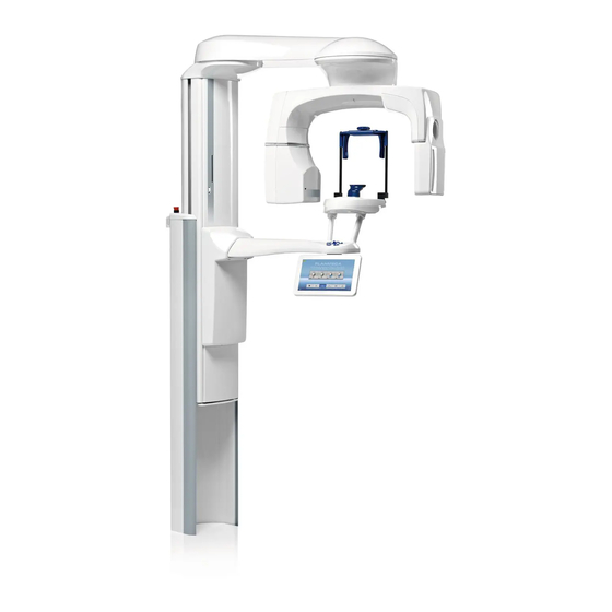
MAIN PARTS General view of X-ray unit C-arm Cephalostat (optional) Sensor Patient support table Patient handles Positioning controls Touch screen Telescopic column Stationary column Chair (included in delivery) 8 Planmeca ProMax 3D Plus & 3D Mid with ProTouch User’s Manual (3D) -
Page 13: Sensors
1 3D sensor for Planmeca ProMax 3D Plus 2 3D sensor for Planmeca ProMax 3D Mid 3 ProFace sensor for Planmeca ProMax 3D Plus and Planmeca ProMax 3D Mid Planmeca ProMax 3D Plus & 3D Mid with ProTouch 9 User’s Manual (3D) -
Page 14: Patient Supports
Head supports (A or B) 1 Adjustable head support 1. Head band 25 2 Temple pads for children 2. Support bars 3 Fastening straps 4 Support bars 10 Planmeca ProMax 3D Plus & 3D Mid with ProTouch User’s Manual (3D) -
Page 15: Exposure Switch
During exposure yellow radiation warning lights illuminate 3) Yellow = Radiation on the exposure switch and on the touch screen. They indicate that the X-ray unit is generating radiation. Planmeca ProMax 3D Plus & 3D Mid with ProTouch 11 User’s Manual (3D) -
Page 16: Emergency Stop Button
A help message will appear on the touch screen. Guide the patient away from the X-ray unit. Then release the emergency stop button. The X-ray unit will automatically restart. 12 Planmeca ProMax 3D Plus & 3D Mid with ProTouch User’s Manual (3D) -
Page 17: Touch Screen
• Home button: To return to the main view from another screen, select the home button at the top right corner of the screen. Planmeca ProMax 3D Plus & 3D Mid with ProTouch 13 User’s Manual (3D) - Page 18 To change a setting, select the settings icon at the top left corner of the main view. This takes you to the settings menu where you can adjust the settings of the X-ray unit. 14 Planmeca ProMax 3D Plus & 3D Mid with ProTouch User’s Manual (3D)
-
Page 19: Patient Positioning Controls
Open / close temple supports (2D imaging) Move image volume down Move image volume up (3D imaging) (3D imaging) Move X-ray unit down Move X-ray unit up Positioning joystick Planmeca ProMax 3D Plus & 3D Mid with ProTouch 15 User’s Manual (3D) - Page 20 Open / close temple supports Press the temple support button to open the temple supports in 2D imaging. The temple supports can be closed by pressing the temple support button again. 16 Planmeca ProMax 3D Plus & 3D Mid with ProTouch User’s Manual (3D)
-
Page 21: Planmeca Promax 3D Plus Programs
Ø140 x H90 mm AIRWAYS Ø60 x H60 mm MIDDLE EAR Ø34 x H42 mm Ø60 x H60 mm TEMPORAL Ø60 x H60 mm BONE VERTEBRAE Ø60 x H60 mm Planmeca ProMax 3D Plus & 3D Mid with ProTouch 17 User’s Manual (3D) -
Page 22: Models
Ø70 x H70 mm BONE VERTEBRAE Ø70 x H70 mm 3D Models 7.3.1 Volume size Program Ø90 mm IMPRESSION Ø90 x H40 mm PLASTER CAST Ø90 x H40 mm 18 Planmeca ProMax 3D Plus & 3D Mid with ProTouch User’s Manual (3D) -
Page 23: Planmeca Promax 3D Mid Programs
Ø100 x H60 mm Ø80 x H80 mm Ø100 x H100 mm Ø200 x H60 mm Ø200 x H100 mm FACE Ø200 x H100 mm Ø200 x H170 mm Planmeca ProMax 3D Plus & 3D Mid with ProTouch 19 User’s Manual (3D) -
Page 24: Ear Nose Throat
Ø80 x H80 mm BONE VERTEBRAE Ø80 x H80 mm 3D Models 8.3.1 Volume size Program Ø80 mm IMPRESSION Ø80 x H40 mm PLASTER CAST Ø80 x H40 mm 20 Planmeca ProMax 3D Plus & 3D Mid with ProTouch User’s Manual (3D) -
Page 25: Patient Exposure
Attaching sensor to C-arm 1. Push the sensor onto the connector on the C-arm. 2. Turn the locking knob over the fastening mechanism. This will secure the sensor in position. Planmeca ProMax 3D Plus & 3D Mid with ProTouch 21 User’s Manual (3D) - Page 26 C-arm. 2. Turn the locking knob 180 degrees. This will release the locking mechanism. 3. Carefully pull the sensor out. 22 Planmeca ProMax 3D Plus & 3D Mid with ProTouch User’s Manual (3D)
- Page 27 Head support A: Attaching adjustable head support Adjustable If you are using the adjustable head support, slide it onto head support the support bars. Support bars Planmeca ProMax 3D Plus & 3D Mid with ProTouch 23 User’s Manual (3D)
- Page 28 50 mm (1.9 in.). Straps with a free length (i.e. when they are not stretched) of over 255 mm (10 in.) do not support the patient’s head firmly. 24 Planmeca ProMax 3D Plus & 3D Mid with ProTouch User’s Manual (3D)
- Page 29 Insert the chin cup into the adapter. Insert the adapter into the holes in the middle of the patient support table. Adapter 9.1.3 Preparing Planmeca Romexis First select the patient. Planmeca ProMax 3D Plus & 3D Mid with ProTouch 25 User’s Manual (3D)
-
Page 30: Selecting Exposure Settings
M = Medium-sized adult L = Large adult Fast forward Forward (skip next screen) NOTE Selecting child patient (XS) will automatically reduce the volume size and patient dose. 26 Planmeca ProMax 3D Plus & 3D Mid with ProTouch User’s Manual (3D) - Page 31 High definition: Better image quality for small targets, e.g. ear bones • High resolution: Sharp images • Endodontic: Very sharp images for endodontic applications and other small targets, e.g. ear bones Planmeca ProMax 3D Plus & 3D Mid with ProTouch 27 User’s Manual (3D)
- Page 32 Factory presets for image resolution Low dose in programs Nose and Sinus mA VALUE PATIENT SIZE kV VALUE mA VALUE WITH ULD Child (XS) Small adult (S) Medium-sized adult (M) Large adult (L) 28 Planmeca ProMax 3D Plus & 3D Mid with ProTouch User’s Manual (3D)
-
Page 33: Patient Size
Factory presets for image resolutions Normal, HD, Hi Res and Endo in other programs mA VALUE PATIENT SIZE kV VALUE mA VALUE WITH ULD Child (XS) Small adult (S) Medium-sized adult (M) Large adult (L) 12.5 Planmeca ProMax 3D Plus & 3D Mid with ProTouch 29 User’s Manual (3D) - Page 34 NOTE You can select one or more options. If all three buttons are gray (no option selected), the screen shows the preset volume positions for the selected program. 30 Planmeca ProMax 3D Plus & 3D Mid with ProTouch User’s Manual (3D)
- Page 35 Select volume height Select jaw half (lower / upper / both halves) NOTE The available options depend on the selected program. Planmeca ProMax 3D Plus & 3D Mid with ProTouch 31 User’s Manual (3D)
- Page 36 X-ray image. Select the last button on the left of the screen to take both images at the same time. ProFace sensor Select 3D face photo 32 Planmeca ProMax 3D Plus & 3D Mid with ProTouch User’s Manual (3D)
-
Page 37: Preparing Patient
NOTE High contrast objects, such as gold teeth or amalgam, may cause artefacts in the image. Place a protective lead apron over the patient’s back if required. Planmeca ProMax 3D Plus & 3D Mid with ProTouch 33 User’s Manual (3D) -
Page 38: Patient Positioning
2. Adjust the X-ray unit to suit the height of the patient. To do this, press either of the height adjusting buttons until the chin cup is approximately level with the patient’s lower jaw. Down 34 Planmeca ProMax 3D Plus & 3D Mid with ProTouch User’s Manual (3D) - Page 39 • You can use fastening straps for additional head support if needed. Refer to section 9.1.2 “Attaching patient supports” on page 23 for details. Planmeca ProMax 3D Plus & 3D Mid with ProTouch 35 User’s Manual (3D)
-
Page 40: Adjusting Volume Position
Press any of the positioning controls (button or Thumb wheel joystick). The lights will automatically switch off after two minutes. To switch them off earlier, press the positioning joystick. Positioning controls Positioning joystick 36 Planmeca ProMax 3D Plus & 3D Mid with ProTouch User’s Manual (3D) - Page 41 (front light) and on the left side (side light) of your patient’s head. Volume center lights: Side light (Y laser) Front light (X laser) Image volume Planmeca ProMax 3D Plus & 3D Mid with ProTouch 37 User’s Manual (3D)
- Page 42 These image volumes cannot be moved to the left or right. Planmeca ProMax 3D Plus: Ø > 70 mm Planmeca ProMax 3D Mid: Ø > 80 mm 38 Planmeca ProMax 3D Plus & 3D Mid with ProTouch User’s Manual (3D)
- Page 43 Positioning joystick (side light = Y laser) Image volume Front NOTE The largest image volume (3D Plus: Ø140 mm / 3D Mid: Ø200 mm) cannot be moved. Planmeca ProMax 3D Plus & 3D Mid with ProTouch 39 User’s Manual (3D)
-
Page 44: Taking A Scout Image Or 2D Views (Lat, Pa Or Lat-Pa)
1. Select the view you wish to take. To take LAT-PA views, select both buttons (LAT and PA). The selected option is shown on the top of the forward button. Select scout or 2D view 40 Planmeca ProMax 3D Plus & 3D Mid with ProTouch User’s Manual (3D) - Page 45 Then take a new exposure as described above. Repeat the procedure until the image volume is in the correct place. Lat-PA NOTE Scout images are not saved in the Planmeca Romexis program. Planmeca ProMax 3D Plus & 3D Mid with ProTouch 41 User’s Manual (3D)
-
Page 46: Taking A 3D Exposure
If you take two horizontal image volumes and a 3D face photo the photo is taken last. You hear a fast ticking sound when the photo is taken. 42 Planmeca ProMax 3D Plus & 3D Mid with ProTouch User’s Manual (3D) - Page 47 If you took two image volumes you must accept the image stitching function in the Planmeca Romexis program. Refer to the Romexis User’s Manual. 6. Guide the patient away from the X-ray unit. Planmeca ProMax 3D Plus & 3D Mid with ProTouch 43 User’s Manual (3D)
-
Page 48: 3D Face Photo
1. Select the patient entry position as described in section 9.4.1 “Selecting patient entry position” on page 2. Guide the patient to the X-ray unit. The patient can sit or stand during the exposure. 44 Planmeca ProMax 3D Plus & 3D Mid with ProTouch User’s Manual (3D) - Page 49 NOTE When you adjust the light position the positioning light moves on your patient’s face. The positioning light on the illustration does not move according to your adjustment. Planmeca ProMax 3D Plus & 3D Mid with ProTouch 45 User’s Manual (3D)
-
Page 50: Taking A 3D Face Photo
You hear a fast ticking sound when the photo is taken. 4. The photo is shown on the computer screen. 5. Guide the patient away from the X-ray unit. 46 Planmeca ProMax 3D Plus & 3D Mid with ProTouch User’s Manual (3D) -
Page 51: 3D Model Exposure
3. Let the material set. The setting time depends on the material used. Wait slightly longer than recommended in the instructions supplied by the manufacturer to ensure proper hardening. Planmeca ProMax 3D Plus & 3D Mid with ProTouch 47 User’s Manual (3D) -
Page 52: Adjusting Exposure Values For Current Exposure
(volume center lights, volume bottom light and incisor light) come on. The volume center Forward field lights cross in the middle of the image volume. 48 Planmeca ProMax 3D Plus & 3D Mid with ProTouch User’s Manual (3D) - Page 53 4. In the Planmeca Romexis program, click 3D > Model Capture. Refer to the Planmeca Romexis User’s Manual for details on Romexis functions. 5. Click the option Add Material in the window that appears. Planmeca ProMax 3D Plus & 3D Mid with ProTouch 49 User’s Manual (3D)
- Page 54 OK. NOTE The calibration exposure values are automatically included at the beginning of the name. The exposure values shown here are only examples. 50 Planmeca ProMax 3D Plus & 3D Mid with ProTouch User’s Manual (3D)
-
Page 55: Taking An Exposure Of An Impression Or Plaster Cast
(volume center lights, volume bottom light and incisor light) come on. The volume center Forward field lights cross in the middle of the image volume. Planmeca ProMax 3D Plus & 3D Mid with ProTouch 51 User’s Manual (3D) - Page 56 6. In the Planmeca Romexis program, click 3D > Model Capture. Refer to the Planmeca Romexis User’s Manual for details on Romexis functions. 52 Planmeca ProMax 3D Plus & 3D Mid with ProTouch User’s Manual (3D)
- Page 57 3D patient exposure. 3. The image is shown on the computer screen. NOTE The Romexis function Model Capture creates surface models (instead of voxel data images). Planmeca ProMax 3D Plus & 3D Mid with ProTouch 53 User’s Manual (3D)
-
Page 58: Settings
Settings that can be entered by service personnel only (password required): • Technical To return to the main view, select the settings icon at the top left corner. 54 Planmeca ProMax 3D Plus & 3D Mid with ProTouch User’s Manual (3D) -
Page 59: User Settings
Time and Time / Date Display Format > Time Display Format. 2. Select the display format you wish to use. 3. Select the green check mark button. Planmeca ProMax 3D Plus & 3D Mid with ProTouch 55 User’s Manual (3D) - Page 60 NOTE The time is set to the local time at the factory. Change the time setting to show the correct time before you start using the X-ray unit. 56 Planmeca ProMax 3D Plus & 3D Mid with ProTouch User’s Manual (3D)
- Page 61 2. Select the mode you wish to use. In demo mode you can practice or demonstrate the functions of the X-ray unit without radiation and PC connection. 3. Select the green check mark button. Planmeca ProMax 3D Plus & 3D Mid with ProTouch 57 User’s Manual (3D)
- Page 62 Note, however, that the automatic function works only if the exposure button is pressed and held down for the entire duration of the exposure. 58 Planmeca ProMax 3D Plus & 3D Mid with ProTouch User’s Manual (3D)
- Page 63 2. If available, select the network settings you wish to view. 3. Select the green check mark button. NOTE Only a service technician or local administrator may change the network settings. Planmeca ProMax 3D Plus & 3D Mid with ProTouch 59 User’s Manual (3D)
- Page 64 5. Press and hold down the exposure button for the duration of the exposure. The C-arm will not move when you take a test exposure. 6. Select the green check mark button. 60 Planmeca ProMax 3D Plus & 3D Mid with ProTouch User’s Manual (3D)
- Page 65 5. Select the green check mark button. NOTE Contact your service technician for help if error message E332 (Arcing across X-ray tube) reappears after a successful seasoning process. Planmeca ProMax 3D Plus & 3D Mid with ProTouch 61 User’s Manual (3D)
-
Page 66: Program Settings
Program > 2500 Reset to Factory Defaults. NOTE You can adjust the preset exposure values temporarily as described in section 9.2.5 “Adjusting exposure values for current exposure” on page 28. 62 Planmeca ProMax 3D Plus & 3D Mid with ProTouch User’s Manual (3D) - Page 67 To manage program settings: Select Program > 2200 Program Features to manage program settings. For details on a specific setting, refer to the manual section that contains the corresponding function. Planmeca ProMax 3D Plus & 3D Mid with ProTouch 63 User’s Manual (3D)
- Page 68 1. Select Program > 2500 Reset to Factory Defaults. 2. Select the green check mark button. NOTE The function will restore the factory defaults in menu Programs (2100). 64 Planmeca ProMax 3D Plus & 3D Mid with ProTouch User’s Manual (3D)
-
Page 69: About Tab
• To view exposure statistics: Select About > 4200 Archive > Exposure Statistics to view statistical data about the X-ray unit. Planmeca ProMax 3D Plus & 3D Mid with ProTouch 65 User’s Manual (3D) -
Page 70: Help Messages
C-arm cannot be moved continuing. lower. H150 Height movement was stopped Clear any obstruction before because the patient support table continuing. cannot be moved lower. 66 Planmeca ProMax 3D Plus & 3D Mid with ProTouch User’s Manual (3D) - Page 71 72 mm. H195 The 3D Model programs must not be Use the 3D Model programs for used for patient imaging. taking exposures of impressions or plaster casts only. Planmeca ProMax 3D Plus & 3D Mid with ProTouch 67 User’s Manual (3D)
-
Page 72: Error Messages
Guide the patient away from the X-ray unit. Then clear the message by touching the green check mark. 68 Planmeca ProMax 3D Plus & 3D Mid with ProTouch User’s Manual (3D) -
Page 73: Cleaning
X-ray unit must be checked and recalibrated by a qualified Planmeca service technician once a year or after every 10 000 exposures if this is sooner. Planmeca ProMax 3D Plus & 3D Mid with ProTouch 69 User’s Manual (3D) -
Page 74: Disposal
- plastic PUR, other plastics Motors Component boards Cables, Copper, transformers steel, transformer oil X-ray tube Packing Wood, cardboard, paper, polystyrene Sensor Return sensor to Planmeca. Other parts 70 Planmeca ProMax 3D Plus & 3D Mid with ProTouch User’s Manual (3D) -
Page 75: Technical Specifications
3D s / 3D Classic / 3D Mid: 1 - 14 mA ±10% 3D Max: 1 - 12.5 mA ±10% • Pan / SmartPan 1 - 16 mA ±10% • Ceph 1 - 16 mA ±10% Planmeca ProMax 3D Plus & 3D Mid with ProTouch 71 User’s Manual (3D) - Page 76 1700 mm (66.9 in.) Magnification: • 3D s / 3D Classic: 1.57 3D Plus / 3D Mid: 1.38, 1.44 or 1.80 3D Max: 1.38, 1.41 or 1.80 72 Planmeca ProMax 3D Plus & 3D Mid with ProTouch User’s Manual (3D)
- Page 77 Transport: • Temperature -20°C - +60°C • Relative humidity 10 - 90% RH (non-condensing) • Air pressure 700 - 1060 hPa Storage: • Temperature -10°C - +50°C Planmeca ProMax 3D Plus & 3D Mid with ProTouch 73 User’s Manual (3D)
- Page 78 Frequency for fluorescent lamps 100 Hz • Even and uniform lighting • No natural light (no windows in the room) • No green objects next to X-ray 74 Planmeca ProMax 3D Plus & 3D Mid with ProTouch User’s Manual (3D)
-
Page 79: Original Manufacturer
TECHNICAL SPECIFICATIONS 18.2 Original manufacturer PLANMECA Oy, Asentajankatu 6, FIN-00880 Helsinki, FINLAND Phone: +358 20 7795 500, Fax: +358 20 7795 555, www.planmeca.com 18.3 Dimensions Scanning ceph or Planmeca ProCeph 1145mm (45.1”) 930mm (36.6”) 810mm (32”) 270mm (10.6”) Scanning ceph or Planmeca ProCeph Planmeca ProMax 3D Plus &... -
Page 80: Minimum Operational Space Requirements
1580 mm 1750 mm 2390 mm 63 in. 69 in. 94 in. X-ray unit with cephalostat 2275 mm 1750 mm 2390 mm 89.6 in. 69 in. 94 in. 76 Planmeca ProMax 3D Plus & 3D Mid with ProTouch User’s Manual (3D) - Page 82 Planmeca Oy | Asentajankatu 6 | 00880 Helsinki | Finland tel. +358 20 7795 500 | fax +358 20 7795 555 | sales@planmeca.com | www.planmeca.com...
Need help?
Do you have a question about the ProMax 3D Plus and is the answer not in the manual?
Questions and answers