Teletek electronics iRIS8 Engineer Programming Manual
Addressable fire alarm control panel
Hide thumbs
Also See for iRIS8:
- Installation manual (33 pages) ,
- User operation & maintenance manual (36 pages)
Table of Contents
Advertisement
Quick Links
iRIS8
Addressable Fire Alarm Control Panel
Engineer
Programming
Manual
Attention:
This manual contains information on limitations regarding product use and
function and information on the limitations as to liability of the manufacturer.
The entire manual should be carefully read.
The information in this manual is a subject to change without notice!
ver. 1.0.8
Advertisement
Table of Contents

Related Manuals for Teletek electronics iRIS8


Summary of Contents for Teletek electronics iRIS8
- Page 1 Addressable Fire Alarm Control Panel Engineer Programming Manual Attention: This manual contains information on limitations regarding product use and function and information on the limitations as to liability of the manufacturer. The entire manual should be carefully read. The information in this manual is a subject to change without notice!
-
Page 2: Table Of Contents
- Addressable Fire Alarm Panel – Installer Programming Table of Contents 1. INTRODUCTION ..................................6 1.1. General Description ............................... 6 1.2. Care of the TFT Screen ............................6 1.3. Quick Review of the Panel Interface ........................6 1.3.1. LED Indication for the System Status ....................6 1.3.2. - Page 3 - Addressable Fire Alarm Panel – Installer Programming 3.3.7. Action Type Input ..........................45 3.3.8. General Type Input ..........................46 3.3.9. Network Type Input ..........................47 3.3.10. Zone Group Type Input ........................47 3.3.11. Device Group Type Input ........................48 3.3.12.
- Page 4 - Addressable Fire Alarm Panel – Installer Programming 1293 DoP No: 138 Teletek Electronics JSC Bulgaria, Sofia 1407, 14А Srebarna Str., Tel.: +359 2 9694 800, Fax: +359 2 962 52 13 e-mail: info@teletek-electronics.bg EN 54-2:1997; EN 54-2:1997/AC:1999; EN 54-2:1997/A1:2006 EN 54-4:1997;...
- Page 5 The manufacturer shall not accept any product, of which no prior notice has been received via the RAN form at: http://teletek-electronics.com/en/ran- form The setup and programming included in the technical documentation shall not be regarded as defects. Teletek Electronics bears no responsibility for the loss of programming information in the device being serviced. CONDITIONS FOR WAIVING THE GUARANTEE This guarantee shall apply to defects in products resulting only from improper materials or workmanship, related to its normal use.
-
Page 6: Introduction
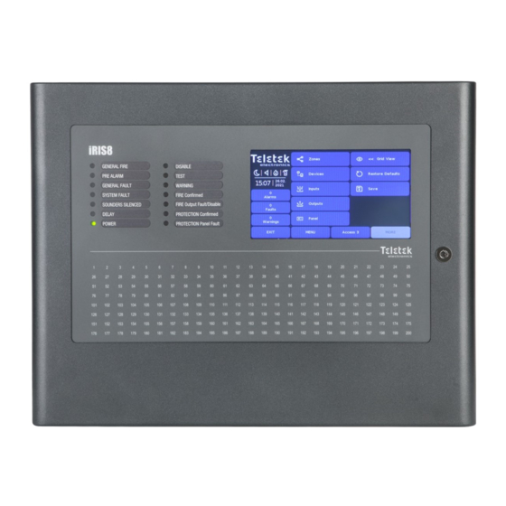
Note: The front door of iRIS8 addressable fire panel is secured with special key-lock (1 pc in iRIS8 S; 2 pcs in iRIS8 B) for limited access only from technical support specialist. - Page 7 - Addressable Fire Alarm Panel – Installer Programming The different system events are displayed also with color LEDs according their type. In case of fire alarm, common or system faults, settings for delays or disablements, tests or warnings, the LED is lighting on permanently. In case of fault in Fire Output on the main control PCB the respective LED is blinking.
-
Page 8: Led Indication For Activated Zones
In the status section are presented the current time and date, and a dynamic field with icons showing the current status of iRIS8 fire alarm panel. The icons are changing according the status for Alarm, Fault, Disable or Reset active events. - Page 9 Disabled** The Fire Protection output is disabled. * Outputs type Sounder, Fire Brigade and Fire Protection (Extinguishing) of the iRIS8 fire alarm panel or other fire panel in the network from which the fire event is received. ** Attention: The iRIS8 indication shows that there are one or more fire panels in the network with disabled for operation output. You can check the...
-
Page 10: Section For Events Review
High DISABLE Normal TESTS Normal WARNINGS Refer to “User Operation & Maintenance Programming Manual for iRIS8” for details about reviewing of system events list. 1.3.6. Functional Buttons for Programming Button Description Entry into Installer’s menus for Programming and Maintenance. Confirmation and saving of the entered parameters. The button appears on the top left corner of the screen after a change of settings or parameters. -
Page 11: Installer Programming
2.1. Changing the Access Level At Access Level 3 the Installer has full rights for entire programming of iRIS8 panel. To enter the Installer menus, press ACCESS button from the Main Screen and introduce the code for Access Level 3 –... -
Page 12: General Information For Digits Introducing
- Addressable Fire Alarm Panel – Installer Programming The following screens present the different type letters/symbols accessible in iRIS8 panel. Cyrillic Letters screen keyboard. Special Letters screen keyboard. Digits screen keyboard. Symbols screen keyboard. Note: Use the special buttons “LAT”, “SYM”, “SPE” or “CYR”... -
Page 13: Programming System Menus
- Addressable Fire Alarm Panel – Installer Programming 3. PROGRAMMING SYSTEM MENUS Press in sequence SYSTEM - PROGRAMMING from Main Screen: Quick summery of the menus: - Settings for Zones (item 3.1) - Quick review of the zones’ status by zone number (item 3.1.5) -
Page 14: Attaching Zone To Groups
- Addressable Fire Alarm Panel – Installer Programming 3.1.1. Attaching Zone to Groups To enter in the submenu for group setting, press “Zone Group” button. The zones in iRIS8 panel can be organized for operation in separate groups. One zone can be associated up to 3 different groups in the system. -
Page 15: Setting Time Delay T2 For Zone
Sounder Groups (A, B, C). The installer can organize up to 127 separate Sounder Groups in a fire alarm system build with iRIS8 panel. -
Page 16: Zones - Quick Review
- Addressable Fire Alarm Panel – Installer Programming It is recommended to arrange the Sounder Groups and to associate the sounders to the respective zone numbers in advance. Panel Settings Zone Sounder Sounder (Sounder GROUP Group menu) GROUP A: 2... -
Page 17: Periphery Devices
The Main board is not a periphery device. Up to 12 periphery devices can be added to the system configuration of iRIS8 panel. The number and type of the functional modules depend on the panel’s model. -
Page 18: Main Power Supply Unit Screen
On the PSU screen are visible the current technical characteristics of the main power supply unit. In system configuration of iRIS8 B and iRIS8 S + iRIS8 Ext are available two separate power supplies units (first for powering of loops 1-4 and second for powering of loops 5-8. -
Page 19: Input-Output Module Screen
- Addressable Fire Alarm Panel – Installer Programming 3.2.4. Input-Output Module Screen At ADDRESS 2 is presented information about the input- output module (OUT1) connected to first main power supply. The screen displays the hardware capability of the module – the number of available inputs and outputs. -
Page 20: Loop Devices - General Information Screen
- Addressable Fire Alarm Panel – Installer Programming 3.2.6. Loop Devices – General Information Screen Attention: The IRIS fire alarm panel searches for new loop devices only when the respective loop controller has been added to the hardware configuration. - Page 21 - Addressable Fire Alarm Panel – Installer Programming The panel is monitoring the current system status of all devices (2) connected to the loop. The status is displayed under the system name of the device and has the following meaning: •...
-
Page 22: Loop Devices - Quick Review
- Addressable Fire Alarm Panel – Installer Programming Every loop device can be removed from the system configuration, regardless of its current operation mode. Press REMOVE button. The removing is immediate without need of confirmation. Note: If after deleting, the removed device is still connected physically to the loop, the panel will find it and will alert with “... -
Page 23: Loop Devices - Sensoiris Devices Settings
- Addressable Fire Alarm Panel – Installer Programming 3.2.8. Loop Devices – SensoIRIS Devices Settings For all SensoIRIS devices are available additional settings after pressing button MORE. The additional settings vary according to the type of device. The following fields are common in the settings for all devices:... - Page 24 - Addressable Fire Alarm Panel – Installer Programming Setting a Device Group number for controlling a LED remote indicator (RI). The RI control option gives the installer possibility to use one LED remote indicator for up to 100 separate detectors without using additional cabling. The installer has to set a group...
-
Page 25: Temperature Detectors
- Addressable Fire Alarm Panel – Installer Programming 3.2.8.2. Temperature Detectors Available models: • SensoIRIS T110 – temperature detector, white (available also in black) • SensoIRIS T110 IS – temperature detector with built-in isolator module, white (available also in black) For detailed description of the main screen of the device see item 3.2.6. - Page 26 - Addressable Fire Alarm Panel – Installer Programming At the device settings screen the installer can review the general and set some additional parameters: Press the “Check” button to enter in a new screen to review the following parameters: - Smoke [%]: Shows in percent the current level of smoke in the detector’s smoke...
-
Page 27: Manual Call Points
- Addressable Fire Alarm Panel – Installer Programming 3.2.8.4. Manual Call Points Available models: • SensoIRIS MCP150 - manual call point, indoor mounting, plastic case, red • SensoIRIS MCP150 IP67 - manual call point, outdoor mounting, plastic case, red •... -
Page 28: Wall Mounted Sounders With Strobe (Vad Devices According En 54-23)
- Addressable Fire Alarm Panel – Installer Programming 3.2.8.6. Wall Mounted Sounders with Strobe (VAD devices according EN 54-23) Available models: • SensoIRIS WSST – sounder with strobe, white • SensoIRIS WSST IS – sounder with strobe and built-in isolator module, white •... -
Page 29: Bases With Sounder And Strobe
- Addressable Fire Alarm Panel – Installer Programming At the device settings screen the installer can review the general and set the additional parameters: Every pressing of the button alternatively changes the sound level between HIGH/ LOW, as this depends on the number of the connected sounders to the loop: - HIGH. -
Page 30: Mini Module
- Addressable Fire Alarm Panel – Installer Programming 3.2.8.9. Mini Module Available model: • SensoIRIS MINP M – mini module with one monitored input The main functionality of the mini module is to monitor and to transfer to control panel the state of the input (state ON or state OFF). -
Page 31: Input/Output Modules
- Addressable Fire Alarm Panel – Installer Programming At the device settings screen the installer can review the general and set the additional parameter: Review the current status of the input: - ON. The input is activated. - OFF (NORMAL State). The input is deactivated. - Page 32 - Addressable Fire Alarm Panel – Installer Programming - SensoIRIS MIO40 - The module has 4 inputs, programmable for activation by an event. Press active button with the name of the module to access the programming of the inputs.
- Page 33 - Addressable Fire Alarm Panel – Installer Programming - SensoIRIS MIO22M - The module has 2 inputs and 2 monitored outputs, programmable for activation by an event. Every of the outputs can be set to operate as monitored or non-monitored type, as the setting is via jumpers on the module’s PCB.
-
Page 34: Zone Modules
- Addressable Fire Alarm Panel – Installer Programming - SensoIRIS MOUT - The module has 1 potential output and is used for connection of conventional sounders. Press active button with the name of the module to access the programming of the output. For setting the activation of the output, refer to description of MIO04. -
Page 35: Mimic Module
- Addressable Fire Alarm Panel – Installer Programming 3.2.8.13. MIMIC Module Available model: • SensoIRIS MIMIC – MIMIC/Repeater module with 32 LED indicators The module has built-in isolator module, which must be connected during installation. The module is specially designed for connection to mimic/repeater panels presenting a geographical plan of the fire alarm system. -
Page 36: Addressing Of Devices
– see item 3.2.9.3. • AUTO ADDRESSING. The auto addressing feature of iRIS8 panel has the purpose to make the installation of the addressable systems easier. By using it the installer could mount all devices without setting address and then do it automatically by a single click in the panel. -
Page 37: Set Address
• Loop Zero Address During any of the ADDRESSING procedures the iRIS8 panel enters in a special operation mode for addressing devices - the panel is busy and does not follow the operation of the other devices in the system. The addressing mode is visualizing with an icon of a “rotating arrows circle”. -
Page 38: Change Address
- Addressable Fire Alarm Panel – Installer Programming 3.2.9.2. Change Address In this submenu the installer can change the address number of a device. To change address of a device, enter in the installer’s menu - ADDRESSING - CHANGE ADDRESS. -
Page 39: Auto-Addressing Menu
- Addressable Fire Alarm Panel – Installer Programming 3.2.9.4. Auto-addressing Menu In this submenu the installer can perform auto-addressing procedure using two methods: auto-addressing by ID numbers or auto-addressing by isolators (devices with built-in isolator module – see APPENDIX B). -
Page 40: Loop Zero Address
Enter INPUTS menu. The menu includes submenus for settings and programming of the different type inputs supported from iRIS8 panel. In a separate submenu the Installer sets group numbers for the inputs and the logic of operation. Quick summery for the submenus: •... - Page 41 - Addressable Fire Alarm Panel – Installer Programming Enter INPUTS submenu. By default, all Inputs are set as NONE Type. The different input types are available for section in a list. Use the arrow buttons, or enter an input number from 1 to The type, as the other specific settings must be confirmed 250.
-
Page 42: Periphery Type Input
- Addressable Fire Alarm Panel – Installer Programming 3.3.1. Periphery Type Input Select this type, when the input number is attached to an input terminal of the input-output main board. Note: This is periphery device with address 2 and the installer can set only inputs from 1-4 – item 3.2.4. -
Page 43: Zone Type Input
- Addressable Fire Alarm Panel – Installer Programming 3.3.3. Zone Type Input Select this type, when the input will be activated from a zone event. Press MORE button to access the additional settings for the zone type input. Note that all introduced changes must be confirmed with APPLY button in this main screen. -
Page 44: Time Type Input
- Addressable Fire Alarm Panel – Installer Programming 3.3.5. Time Type Input Select this type, when the input will be activated on a time schedule. Press MORE button to access the additional settings for Set the GROUP Number from 1-250, according the the time type input. -
Page 45: Action Type Input
- Addressable Fire Alarm Panel – Installer Programming 3.3.7. Action Type Input Select this type, when the input will be activated from an action event. Press MORE button to access the additional settings for the action type input. Note that all introduced changes must be confirmed with APPLY button in this main screen. -
Page 46: General Type Input
- Addressable Fire Alarm Panel – Installer Programming 3.3.8. General Type Input Select this type, when the input will be activated from a general event. Press MORE button to access the additional settings for the general type input. Note that all introduced changes must be confirmed with APPLY button in this main screen. -
Page 47: Network Type Input
- Addressable Fire Alarm Panel – Installer Programming 3.3.9. Network Type Input Select this type, when the input will be activated from a network device (panel/repeater number). Press MORE button to access the additional settings for Set the GROUP Number from 1-250, according the the network type input. -
Page 48: Device Group Type Input
- Addressable Fire Alarm Panel – Installer Programming 3.3.11. Device Group Type Input Select this type, when the input will be activated from a device, included in a group. Press MORE button to access the additional settings for Set the GROUP Number from 1-250, according the the device group type input. -
Page 49: Outputs
- Addressable Fire Alarm Panel – Installer Programming 3.4. Outputs Enter OUTPUTS menu. By default, all Outputs are set as NONE Type. The different output types are available for section in a Use the arrow buttons, or enter an output number from 1 list. -
Page 50: Periphery Type Output
- Addressable Fire Alarm Panel – Installer Programming 3.4.1. Periphery Type Output Select this type, when the output number is attached to an output terminal of the input-output main board. Note: This is periphery device with address 2 and the installer can set only the relay outputs from 1-4 – item 3.2.4. -
Page 51: Network Type Output
- Addressable Fire Alarm Panel – Installer Programming 3.4.3. Network Type Output Select this type, when the output will activate a network device (panel/repeater number). Press MORE button to access the additional settings for Introduce the settings for network type output: the network type output. -
Page 52: Event Type Output
- Addressable Fire Alarm Panel – Installer Programming 3.4.5. Event Type Output Select this type, when in case of activation of input logic, the output has to perform a general event. Press MORE button to access the list with general events. All introduced changes must be confirmed with APPLY button. -
Page 53: Panel
3.5.1. Setting Access Codes and Levels for Operation There are three access levels for control in iRIS8 addressable fire alarm panel with different functionalities and rights for operation. Four access codes can be set with different access level for users. - Page 54 - Addressable Fire Alarm Panel – Installer Programming Fields description: • Access Code Number – Use the left/right buttons to change the code number. Up to 4 code numbers are available for operation. • Access Code – Active button for changing the set code combination.
-
Page 55: Network Settings
TCP/IP port for communication between the panels in the network. The port number must be Port set one and the same for all connected panels. In case of changing the port number, the iRIS8 panel must be reset from the main screen. - Page 56 - Addressable Fire Alarm Panel – Installer Programming 3.5.2.2. Panels After Enabling the Network, every panel starts looking for other panels in the network. If a new panel is found in the system it is added to the panels list with the number set into its Network Settings. The panels are displayed also with unique name (if set), IP address and current status in the network.
- Page 57 – see item 3.5.2.2. • The iRIS8 panel must be deleted from the rest panels in the network and ADDED again after all settings are completed. It is recommended, before making a Restore Defaults of any panel, to save its current system configuration as TDF file using ProsTE specialized programming software.
-
Page 58: Disable Menu
- Addressable Fire Alarm Panel – Installer Programming 3.5.3. Disable Menu This a submenu to enabling/disabling the earth fault, battery high resistance indication and internal buzzer signalization. Enter PANEL - DISABLE menu. ATTENTION: The indication for “Battery High Resistance” must be enabled for conformity with... - Page 59 At second screen for SOUNDERS MODE are set parameters for “Evacuation Settings”. The settings into this screen are obligatory when Voice Evacuation Panels (PASO) are connected to iRIS8 panel via RS484 interface connection. The settings are concerning the operation of the sounders on the site in case of fire alarm situation.
-
Page 60: Phase Evacuation (Stage 1 And Stage 2)
- Addressable Fire Alarm Panel – Installer Programming 3.5.4.1. Phase Evacuation (Stage 1 and Stage 2) Press MORE button again to enter the last screen for setting a phase evacuation of a building in case of a fire alarm situation. -
Page 61: Setting Paso Panels (Evac Zone Button)
3.5.4.2. Setting PASO panels (EVAC ZONE Button) When to the iRIS8 panel is connected one or several (up to 5) Evacuation Voice Panels (PASO), their operation must be set in a separate menu accessible after pressing the EVAC ZONES button. -
Page 62: Language Selection
- Addressable Fire Alarm Panel – Installer Programming 3.5.6. Language Selection The iRIS8 panel supports operation in different languages. By default, it is set English language for the menus. Changing the language is quick without need of confirmation. Enter PANEL – LANGUAGE. -
Page 63: Fat/Fbf & Espa444 Settings Menus
3.5.10.1. FAT/FBF (RS232 Communication Protocol) The iRIS8 addressable fire alarm panel can be used in systems for announcing a fire brigade unit for a fire alarm situation in the protected site. Such systems are mainly used in Germany, as the fire panel is connected to FAT/FBF (Fire Brigade indication panel with integrated Fire Brigade operation panel) type control panels via standard serial interface RS232. - Page 64 SensoIRIS MIO-22, MIO-22 M, MIO-04, MOUT modules. The programmable inputs and outputs in iRIS8 panel are listed at the left side of the menu and have the following meaning: Door switch input This is an input for receiving a signal that the door of the key safe is opened.
-
Page 65: Restore Defaults
3.6. Restore Defaults In the RESTORE DEFAULTS menu, the Installer can reset the iRIS8 panel to the factory settings of all menus. The language of menus will restore in English. It is necessary to program also the Network and Panel settings to restore the operation of the panel in the network. -
Page 66: Maintenance System Menus
- Addressable Fire Alarm Panel – Installer Programming 4. MAINTENANCE SYSTEM MENUS Press in sequence SYSTEM - MAINTENANCE from Main Screen: Quick summery of the menus: • Time – Set the current time – item • Date – Set the current date – item •... -
Page 67: Setting Daytime Mode
- Addressable Fire Alarm Panel – Installer Programming 4.3. Setting Daytime Mode This is a menu for setting time day time mode for operation of the panel. In Day mode the detectors operate with alarm level which has been programmed as day mode. This is usually a level of lower sensitivity. It lowers the risk of false alarms caused by dust, cigarette smoke, etc. -
Page 68: Setting Outputs Delay
- Addressable Fire Alarm Panel – Installer Programming 4.4. Setting Outputs Delay This is a menu for setting time delay for activation of the panel’s outputs on the main PCB. This provides the possibility of checking the authenticity of the alarm before the sounders and extinguishing on the site to be turned on (an official visits the site and inspects for fire). -
Page 69: Review The Log Memory For Events
- Addressable Fire Alarm Panel – Installer Programming 4.5. Review the Log Memory for Events This menu allows the installer to review the system events recorded in the panel’s memory log file and to print them if a printer is available in the panel’s configuration. The capacity of the panel’s memory log file is 10000 events. In a special submenu “Clear Log”... -
Page 70: Performing Tests
- Addressable Fire Alarm Panel – Installer Programming 4.7. Performing Tests In this menu the installer performs full testing of the operability of zones, devices, panel sounder outputs and the LED indication of the front panel. Enter MAINTENANCE - TEST menu. The test submenus are performed with active buttons in blue. -
Page 71: Indication Test
This is a menu for testing the operability of the monitored sounder outputs on the control panel’s PCB. Note: The Sounder Output Test will be applied to all SND outputs of the used iRIS8 fire alarm panel. The number of the SND outputs depends on the model and configuration: - Single panel iRIS8 S (up to 4 loops) –... -
Page 72: Performing Disablements
- Addressable Fire Alarm Panel – Installer Programming 4.8. Performing Disablements This is a special maintenance menu for quick access to zones and devices menus and performing disabling/enabling of the operation. Additional grid view menu for zones and devices makes the reviewing more easer and informative. -
Page 73: Outputs
Maintenance menus. Performing Firmware Update of iRIS8 Panel To perform a firmware update of your iRIS8 panel, download the last published firmware version (BIN file) from the manufacturer’s official web site: http://www.teletek-electronics.com or ask your local distributer of the equipment. -
Page 74: Display Calibration And Settings
Do not use sharp instruments for pressing the screen, like screwdrivers, tweezers or pliers, because they can scratch or break the plastic surface of the screen and the iRIS8 panel to become not operable! Enter COORDINATES submenu. The calibration procedure requires selection (3 times) of some specific places on the screen, following the displayed messages on the middle. -
Page 75: Colors Review
- Addressable Fire Alarm Panel – Installer Programming 5. Message for succesful calibration is diplayed. Press the If the calibration is unsuccessful, it is announced with screen anywhere to return to DISPLAY menu. message for failure. In that case is recommended to perform the calibration again. -
Page 76: View Insulator Active
Routine Maintenance iRIS8 S and iRIS8 B control panels do not require any specific maintenance. To clean the panel’s surface, use a dry cloth. Detergents or solvents should not be used to clean the panel and care must be taken that water does not enter the enclosure. -
Page 77: Appendix А - General Menu Structure
- Addressable Fire Alarm Panel – Installer Programming APPENDIX А - General Menu Structure PROGRAMMING MENUS – Installers Access Level 3... - Page 78 - Addressable Fire Alarm Panel – Installer Programming APPENDIX А - General Menu Structure - Continue MAINTENANCE MENUS – Installers Access Level 3...
-
Page 79: Appendix B - Sensoiris Device Types
- Addressable Fire Alarm Panel – Installer Programming APPENDIX B - SensoIRIS Device Types Device System Name Description Isolator Module Available SensoIRIS S130 Optical-smoke detector SensoIRIS S130 IS Optical-smoke detector Yes (built-in) SensoIRIS T110 Temperature detector SensoIRIS T110 IS... -
Page 80: Appendix C - Initial Start-Up Of The System
- Addressable Fire Alarm Panel – Installer Programming APPENDIX C - Initial Start-up of the System... -
Page 81: Appendix D - "Two Steps Of Alarming" Operation Algorithm
- Addressable Fire Alarm Panel – Installer Programming APPENDIX D - “Two steps of alarming” Operation Algorithm Note: The set time delays for activation of the sounders and the panel outputs - T1 and T2 - will start running, when are enabled in MAINTENANCE –... - Page 82 - Addressable Fire Alarm Panel – Installer Programming APPENDIX D - “Two steps of alarming” Operation Algorithm - Continue Note: When the general time delay for activation T1 is disabled (T1=0), then the individually set T2 time delays for the activated zone in fire alarm start running.
-
Page 83: Appendix E - Sensoiris Sounders Consumption
- Addressable Fire Alarm Panel – Installer Programming APPENDIX E - SensoIRIS Sounders Consumption Tables: Calculation of the consumption of SensoIRIS sounders. To calculate the total consumption of the sounders in the loop and to define the proper sound level, you can use the Table a below, as fill in the number of the used sounders according their type. -
Page 84: Appendix F - Sensoiris Sounders Sound Types
- Addressable Fire Alarm Panel – Installer Programming APPENDIX F - SensoIRIS Sounders Sound Types Tone Tone Type Tone Description/Application 970Hz 800Hz/970Hz @ 2Hz 800Hz - 970Hz @ 1Hz 970Hz 1s OFF/1s ON 970Hz, 0.5s/ 630Hz, 0.5s 554Hz, 0.1s/ 440Hz, 0.4s (AFNOR NF S 32 001) 500 - 1200Hz, 3.5s/ 0.5s OFF (NEN 2575:2000) -
Page 85: Appendix G - Messages For Events
- Addressable Fire Alarm Panel – Installer Programming APPENDIX G - Messages for Events Note: The messages are followed from a Panel, Zone and Loop number, and also Device address, when the event is received from another panel in the network. - Page 86 - Addressable Fire Alarm Panel – Installer Programming Earth Fault function DISABLED The Earth Fault indication is disabled. Sounder Disabled The Sounders are disabled. Fire Brigade Output Disabled The fire output is disabled. Fire Protection Output Disabled The extinguishing output is disabled.
- Page 87 www.teletek-electronics.com Address: Bulgaria, 1407 Sofia, 14А Srebarna Str. Tel.: +359 2 9694 800, Fax: +359 2 962 52 13 e-mail: info@teletek-electronics.bg English, RevA, 10/ 2021...
Need help?
Do you have a question about the iRIS8 and is the answer not in the manual?
Questions and answers