Teletek electronics iRIS8 Installation Manual
Addressable fire alarm control panel
Hide thumbs
Also See for iRIS8:
- Engineer programming manual (87 pages) ,
- User operation & maintenance manual (36 pages)
Table of Contents
Advertisement
Quick Links
iRIS8
Addressable Fire Alarm Control Panel
Installation
Manual
Attention:
This manual contains information on limitations regarding product use and
function and information on the limitations as to liability of the manufacturer.
The entire manual should be carefully read.
The information in this manual is a subject to change without notice!
Advertisement
Table of Contents

Related Manuals for Teletek electronics iRIS8


Summary of Contents for Teletek electronics iRIS8
- Page 1 Addressable Fire Alarm Control Panel Installation Manual Attention: This manual contains information on limitations regarding product use and function and information on the limitations as to liability of the manufacturer. The entire manual should be carefully read. The information in this manual is a subject to change without notice!
-
Page 2: Table Of Contents
4.1. Main Power Supply and Back-up Battery Connection ................16 4.2. iRIS8 B Common Modular Terminal Block ....................17 4.3. iRIS8 B and iRIS8 S Outputs Control Module (OUT1) ................18 4.3.1 OUT1 Elements Description ....................... 18 4.3.2 Connection of Sounders ......................19 4.3.3 Connection of Signalling Devices .................... - Page 3 - Addressable Fire Alarm Panel – Installation Manual 1293 DoP No: 138 Teletek Electronics JSC Bulgaria, Sofia 1407, 14А Srebarna Str., Tel.: +359 2 9694 800, Fax: +359 2 962 52 13 e-mail: info@teletek-electronics.bg EN 54-2:1997; EN 54-2:1997/AC:1999; EN 54-2:1997/A1:2006 EN 54-4:1997;...
- Page 4 The manufacturer shall not accept any product, of which no prior notice has been received via the RAN form at: http://teletek-electronics.com/en/ran- form The setup and programming included in the technical documentation shall not be regarded as defects. Teletek Electronics bears no responsibility for the loss of programming information in the device being serviced. CONDITIONS FOR WAIVING THE GUARANTEE This guarantee shall apply to defects in products resulting only from improper materials or workmanship, related to its normal use.
-
Page 5: Introduction
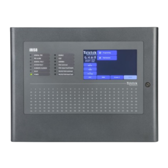
Ext Figure 1. Front view of iRIS8 series. The metal boxes of iRIS8 S and iRIS8 Ext can be easily mounted to each other in a module structure with all hardware connections hidden inside - see for details item 2.4. -
Page 6: General Specifications
(LED) indication. Separate operator and engineer passwords provide access to the functions of the panel. Up to 8 loop controllers (iRIS8 TTE Loop expander) can be supplemented to the iRIS8 B outputs control modules, and up to 4 to the iRIS8 S and iRIS8 Ext PCBs. -
Page 7: Working Environment
Internal resistance of the accumulator battery Ri....< 0.3 Ohm • Number of Batteries: iRIS8 B: ..............2 x 12V/ 18Ah iRIS8 S and iRIS8 Ext ........... 1 x 12V/ 18Ah • Battery Size: ............... 167x181x76mm • Battery type: ............... rechargeable, sealed lead-acid type •... - Page 8 - Addressable Fire Alarm Panel – Installation Manual List of the fuses • General Power Supply, T Type: ......... 4A • Outputs, PTC Type: Fire Protection, Fire, Fault........3x0.1A Auxiliary ..............1x0.3A Auxiliary ..............1x0.5A Sounder ..............2x1A •...
-
Page 9: Installation
The temperature must be within -5ºС and + 40ºC. The fire panel is not water- proof! Attention: The front cover of iRIS8 panels is mounted to the box bottom with hinges fixed with dismountable rivets. The angle of opening of the front cover must not be greater than 110° - see Figure 3! -
Page 10: Wall Mounting
• For wall mounting, use the drilling paper template to mark the mounting holes – Figure 4. • For mounting of iRIS8 B, drill holes Ø8mm and for mounting of iRIS8 S – Ø6 ÷ Ø8mm. iRIS8 S, iRIS8 Ext... -
Page 11: Built-In Mounting
2.3. Built-in Mounting The built-in mounting is designed for iRIS8 S panel box and it is applied in 25mm thick drywalls. The built-in mounting is performed with special kit containing: metal base, metal decorative frame and set of fixing elements – Figure 6. -
Page 12: Module Structures
Remove the first row plastic caps from the top and bottom side of iRIS8 S box. • Insert the metal bottom of iRIS8 S into the metal base and fix them to each other it with the screws. Use 3 pcs of screws M4x12 (DIN 966) for fixing the metal box of iRIS8 S to the metal base. - Page 13 - Addressable Fire Alarm Panel – Installation Manual The joining of the panels to each other is all and the same for all metal boxes. One module structure can be built with two, three or four boxes according the type and requirements of the fire installation. The modular structures allow expanding the capability of already existing installations at low cost and with minimum additional expenses.
-
Page 14: System Components
Main control module PCB – see Figure 14. Note: The front door of iRIS8 addressable fire panel is secured with special key-lock (1 pc in iRIS8 S; 2 pcs in iRIS8 B) for limited access only from technical support specialist. -
Page 15: Configuration Of The Basic Modules
- Addressable Fire Alarm Panel – Installation Manual 3.3. Configuration of the Basic Modules The iRIS8 series panels are designed with a range of basic modules organized in factory configuration according the model – Figure 14. Elements’ description: 1 - Main power supply unit - see item 4.1. -
Page 16: Basic Modules Description
- Addressable Fire Alarm Panel – Installation Manual 4. BASIC MODULES DESCRIPTION The iRIS8 is delivered with plug connectors (2- and 3-position) mounted to the PCB control modules of OUT1, OUT2, Loop expander(s) and interface communication module – see Figure 14. The plug connectors are used for quick wire installation. -
Page 17: Iris8 B Common Modular Terminal Block
4.2. iRIS8 B Common Modular Terminal Block In iRIS8 B, the 110÷230V AC power source is connected to a special modular terminal, which provides the power supply to the two independent main power supply units. The connection of the power units is factory done. The installer must connect only the 110÷230V AC power source to the modular terminal. -
Page 18: Iris8 B And Iris8 S Outputs Control Module (Out1)
4.3. iRIS8 B and iRIS8 S Outputs Control Module (OUT1) The Outputs Control module OUT1 in iRIS8 B and iRIS8 S addressable fire alarm panels is a structure of two PCBs mounted to each other via interface slot: Monitored outputs PCB and Programmable Relays PCB. -
Page 19: Connection Of Sounders
- Addressable Fire Alarm Panel – Installation Manual 4.3.2 Connection of Sounders To the monitored output SND, could be connected several sounders - Figure 18. The maximum number of sounders that could be connected in the circuit, depends on their total current consumption, which must not exceed 1A. -
Page 20: Iris8 B And Iris8 Ext Outputs Control Module (Out2)
4.4. iRIS8 B and iRIS8 Ext Outputs Control Module (OUT2) The OUT2 control module is the second outputs module in configuration of iRIS8 B and iRIS8 Ext panels. The module cannot work independently. OUT2 module must be connected to Main (Indication LCD and LED) control module PCB for proper operation of the connected loop expanders. -
Page 21: Permissible Cable Length
Screened, PH90 DIN EN 50200 TS IEC 60331-2, 300/500V, 2x0.8/1.5mm *This cable is tested and approved. ATTENTION: iRIS8 TTE loop controller supports up to 250 devices! To ensure the correct operation of the system is necessary to make some calculations in advance: 1. -
Page 22: Loop Expander Elements Description
4.5.3 Loop Line Connection Connect the loop line to the iRIS8 Loop expander as strictly observe the polarity. The “Channel A” is the starting point for addressing the connected devices, and “Channel B” is the end point. The addressing methods are described in item 5.2. -
Page 23: Finding Short-Circuit In The Loop Line
- Addressable Fire Alarm Panel – Installation Manual In iRIS8 B can be added up to 8 loop expanders, distributed in two series – Loop expanders 1-4 connected to OUT1 control module and Loop expanders 5-8 connected to OUT2 control module. -
Page 24: Interface Communication Module
Figure 28 The connection of iRIS8 panel to IRIS Printer is with a flat interface 800 mm long cable, supplied in the spare parts kit of IRIS Printer - connector types DB9 to DC10. Connect the DB9 connector to Printer terminal of the interface module and the IDC10 to IRIS Printer PCB. -
Page 25: Fat/Fbf Panels Connection
• The connections between iRIS8 fire panel and the adapter box for key safe, and the Dialer are realized using the addressable modules with inputs and outputs (MIO22, MIO22M, MOUT, MINP, MIO04, MIO40), as for the outputs can be used also the panel’s programmable relay outputs –... -
Page 26: Paso Panels Connection
When the fire is extinguished, the Fire Brigade Officer returns all the keys back to the key safe and locks it. Now the iRIS8 panel must be reset to normal operation mode. After resetting, the adapter of the key safe is locked, the Dialer is returned to stand-by mode, and all of the messages for alarms and warnings are cleared. -
Page 27: Redundant Network Module
4.6.5. Redundant Network Module The iRIS8 addressable fire alarm panel is designed with option for connection in a redundant network with other iRIS8, IRIS PRO, SIMPO and IRIS/SIMPO Repeater panels (up to 64). The redundant network is based on RS485 interface. - Page 28 - Addressable Fire Alarm Panel – Installation Manual iRIS8 (interface module) Redundant Network Module External power supply unit Repeater Figure 33 The maximum cable length between two network modules and/ or repeater panel is 1000m. SIMPO Fire panel iRIS8 Fire panel...
-
Page 29: Main Control Module Pcb
(up to 64). The LAN connection can be direct panel-to-panel or by means of a HUB via TCP/IP protocol. To operate in LAN network with other iRIS8 and Repeater TFT panels the installer must set for all panels “LAN” type of the communication protocol. -
Page 30: Supplementary Information
Attention: The Interface module and Main control module PCB are not periphery devices! Up to 12 periphery devices can be added to the system configuration of iRIS8 panel. The number and type of the functional modules depend on the panel’s model. -
Page 31: Methods For Addressing Loop Devices From The Panel
• The devices are directly connected to the panel via iRIS8 TTE Loops. The panel will recognize them and gives automatically addresses according the order of the devices in the line. The panel will start with the first free address in the system configuration. - Page 32 Routine Maintenance iRIS8 S and iRIS8 B control panels do not require any specific maintenance. To clean the panel’s surface, use a dry cloth. Detergents or solvents should not be used to clean the panel and care must be taken that water does not enter the enclosure.
- Page 33 www.teletek-electronics.com Address: Bulgaria, 1407 Sofia, 14А Srebarna Str. Tel.: +359 2 9694 800, Fax: +359 2 962 52 13 e-mail: info@teletek-electronics.bg 18021048, RevA, 10/ 2021...
Need help?
Do you have a question about the iRIS8 and is the answer not in the manual?
Questions and answers