Advertisement
Quick Links
ATTENTION: Read carefully this installation Instructions before
installing the device! This manual is subject to change without
notice!
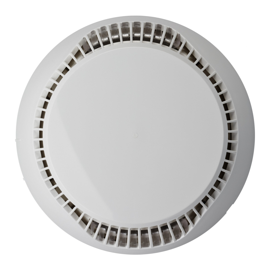
SensoIRIS T110 IS is аn addressable heat detector with built-in isolator
module designed for installing in addressable fire alarm systems supporting
TTE communication protocol. The detector is powered on from the panel
and can be controlled via the communication protocol.
The detector SensoIRIS T110 IS is compatible with fire base B124.
Installation Instructions
1
. Choose the proper place for installation of the fire detector. Refer to
the given installation instructions. Note: Do not install the detector near to
natural heat sources, e.g. above cookers, ovens or fire places.
SensoIRIS T110 IS
2. If you want to "lock" the detector to the base remove the little "tooth"
on the top of the locking mechanism (located in the narrow part).
Intelligent analogue addressable
3. Mount the fire base on the ceiling of the protected premises using fixings
fire alarm heat detector
according the mounting surface.
with built-in isolator module
4. Connect the detector base to the fire panel using the wiring diagram.
ATTENTION: Disconnect the loop power before installing the detector!
5. Insert the detector into the base and rotate clockwise until it drops into
place - the short mark on the base fits with that on the detector body.
Continue to rotate the detector until the detector mark coincides with the
19
long mark on the base - a click is heard.
0832
DoP No: 024
6. Test the detector for proper operation and LED indication.
ATTENTION: The blinking of the two LEDs can be managed from the control
1139j/01
Tested by
panel (ON/ OFF).To turn the blinking on/ off you have to be a User with
Access control level 3.
Choose in consecutiveness from the control panel: System - Programming -
Teletek Electronics JSC
Devices - Loop. Find the installed detector, as enter address, loop and zone
Address: 14A Srebarna Str,
number - the panel automatically will recognize the type of the detector.
Choose the button MORE to enter in the additional settings menu. The
1407 Sofia, Bulgaria
blinking of LEDs is turned on/ off with pressing the ON/OFF button in the
"Led Blink" field.
EN 54-5:2000+A1:2002
7. If the detector has been locked to the base, when open it for a service
EN 54-17:2005/ AC:2007
schedule maintenance and cleaning you have to use a plain screw-driver.
Light press with the screw-driver into the base opening and at the same time
rotate the detector head counter-clockwise.
Essential characteristics
Performance
Warranty
Pass
Performance under fire conditions
All detectors carry on a warranty valid from the date of manufacture. The
Operational reliability
Pass
date of manufacture can be checked by the code on the back of the detector.
Durability of operational reliability:
The first two numbers represent the year and the last two - the month. For
example: The date code "17 07", means the detector is manufactured in
Temperature resistance
Pass
July, 2017.
Humidity resistance
Pass
To return goods for warranty service, please contact with your local
distributer for details.
Shock and vibrationresistance
Pass
Corrosion resistance
Pass
TECHNICAL SPECIFICATIONS / CARACTERÍSTICAS TÉCNICAS / ТЕХНИЧЕСКИ ХАРАКТЕРИСТИКИ
Operating Voltage Range. . . . . . . . . . . . . . . . . . . . . . . . . . . . . Voltaje de alimentación . . . . . . . . . . . . . . . . . . . . . . . . . . . . . . . . . . . . . . Захранващо напрежение . . . . . . . . . . . . . . . . . . . . . . . . . . . . . . . . . . 16 - 32VDC (Nom. 27VDC)
!
Installation /
Consumption in quiescent state, no communication . . . . . . . . Consumo en estado sin activar, sin comunicación . . . . . . . . . . . . . . . . . Консумация в незадействано състояние, без комуниакция . . . . . . < 170μA@27VDC
Consumption in quiescent state, with communication . . . . . . . Consumo en estado sin activar, con comunicación . . . . . . . . . . . . . . . . Консумация в незадействано състояние, с комуниакция . . . . . . . . < 290μA@27VDC
Instalación/
Consumption in alarm state, with communication . . . . . . . . . . Consumo en estado de alarma, con comunicación . . . . . . . . . . . . . . . . Консумация в алармено състояние, с комуникация . . . . . . . . . . . . 6.5mA
Инсталиране
Class selectable from the control panel . . . . . . . . . . . . . . . . . . Clase, panel de control seleccionable. . . . . . . . . . . . . . . . . . . . . . . . . . . Клас, избираем от контролния панел . . . . . . . . . . . . . . . . . . . . . . . . A1/R, A2/S*, B/S*
(in accordance with EN54-5)
Output in alarm state at terminal RI (terminals 4/ 1) . . . . . . . . Corriente eléctrica en estado de alarma del RI (terminales 4/1) . . . . . . . Ток в алармено състояние на клема RI (клеми 4/ 1) . . . . . . . . . . . . 7.5 mA (max)/ 7.5V
-10°C ÷ +60°C
Relative humidity resistance . . . . . . . . . . . . . . . . . . . . . . . . . . Resistencia a humedad relativa . . . . . . . . . . . . . . . . . . . . . . . . . . . . . . . Устойчивост на относителна влажност. . . . . . . . . . . . . . . . . . . . . . . (93 ± 3)% @ 40°C
Dimensions (with base) . . . . . . . . . . . . . . . . . . . . . . . . . . . . . . Dimensiones (con base) . . . . . . . . . . . . . . . . . . . . . . . . . . . . . . . . . . . . . Размери (с основа). . . . . . . . . . . . . . . . . . . . . . . . . . . . . . . . . . . . . . . 103x42mm
Degree of protection. . . . . . . . . . . . . . . . . . . . . . . . . . . . . . . . . Grado de protección . . . . . . . . . . . . . . . . . . . . . . . . . . . . . . . . . . . . . . . . Степен на защита. . . . . . . . . . . . . . . . . . . . . . . . . . . . . . . . . . . . . . . . IP30*
Indoor use /
* Not tested by LPCB/ No probado por LPCB/ Не е тествано в LPCB
Montaje interno /
Вътрешен монтаж
2
2
0.4mm - 2.0mm
ISOLATOR MODULE TECHNICAL SPECIFICATIONS / CARACTERÍSTICAS TÉCNICAS DEL AISLADOR / ТЕХНИЧЕСКИ ХАРАКТЕРИСТИКИ НА ИЗОЛАТОРА
Vmax . . . Max. line voltage . . . . . . . . . . . . . . . . . . . . . . . . . . . . . . . . . . Voltaje máx. en el círculo . . . . . . . . . . . . . . . . . . . . . . . . . . . . . . Максимално напрежение в кръга. . . . . . . . . . . . . . . . . . . . . . . . . . . . . . 32V
~110g
Vnom . . . Nom. line voltage . . . . . . . . . . . . . . . . . . . . . . . . . . . . . . . . . . Voltaje nom. en el círculo . . . . . . . . . . . . . . . . . . . . . . . . . . . . . . Номинално напрежение в кръга. . . . . . . . . . . . . . . . . . . . . . . . . . . . . . . 28V
Vmin . . . . Min. line voltage . . . . . . . . . . . . . . . . . . . . . . . . . . . . . . . . . . . Voltaje mín. en el círculo . . . . . . . . . . . . . . . . . . . . . . . . . . . . . .
without base/
Outdoor use
Vso max . Max. voltage at which the device isolates* . . . . . . . . . . . . . . Voltaje máx. en que el dispositivo interrumpirá el círculo* . . . . . Макс. напрежение, при което устройството прекъсва кръга* . . . . . . . 7.5V
peso sin base incluida /
Montaje externo /
без основа
Vso min. . Min. voltage at which the device isolates* . . . . . . . . . . . . . . . Voltaje mín. en que el dispositivo interrumpirá el círculo* . . . . . Мин. напрежение, при което устройството прекъсва кръга* . . . . . . . . 5.9V
Външен монтаж /
Vsc max . Max. voltage at which the device reconnects** . . . . . . . . . . . Voltaje máx. en que el dispositivo restablecerá el círculo** . . . . Макс. напрежение, при което устройството възстановява кръга** . . . 6.7V
Vsc min. . Min. voltage at which the device reconnects** . . . . . . . . . . . Voltaje mín. en que el dispositivo restablecerá el círculo** . . . . Мин. напрежение, при което устройството възстановява кръга** . . . . 5V
Ic max . . . Max. rated continuous current with the switch closed . . . . . . Corriente continua máx. en llave cerrada (circuito continuo) . . . Макс. продължителен ток при затворен ключ (непрекъснат кръг) . . . 0.7A
Is max . . . Max. rated switching current (e.g. under short circuit) . . . . . . Corriente máx. conmutable (por ejemplo, en cortocircuito). . . . .
II max . . . Max. leakage current with the switch open (isolated state) . . Corriente de escape en llave abierta (circuito discontinuo). . . . .
18020199, RevD, 02/ 2019
Zc max . . Max. series impedance with the switch closed. . . . . . . . . . . . Impedancia máx. de serie en llave cerrada (circuito continuo) . . Макс. сериен импеданс при затворен ключ (непрекъснат кръг) . . . . . 0.12Ω@28VDC; 0.15 @15VDC
* Note: Switches from closed to open / Observación: Conmuta de estado cerrado a estado abierto /
** Note: Switches from open to closed / Observación: Conmuta de estado abierto a estado cerrado / Забележка Превключва от отворено към затворено състояние
English
Installation Instruction
(en conformidad con EN54-5)
Instrucciones de instalación
Español
ATENCIÓN: ¡Lea atentamente las instrucciones antes de proceder
a instalar el detector! ¡El fabricante se reserva el derecho de
realizar cambios sin notificación previa!
SensoIRIS T110 IS – Detector de temperatura analógico con aislador
incorporado. El detector está destinado a utilizarse en sistemas de alarma
analógicos, que mantienen el protocolo de comunicación TTE. El detector
recibirá alimentación del panel y podrá ser controlado mediante el protocolo
de comunicación.
El detector SensoIRIS T110 IS es compatible con la base B124.
Instrucciones de instalación
1. Seleccione un lugar apropiado para instalar el detector. Siga las
instrucciones que se han dado para la instalación. Observación: No instale
el detector cerca de fuentes de calor naturales, por ejemplo, encima de
cocinas, hornos o chimeneas.
2. Si desea bloquear el detector en la base, retire la pestaña de la punta
del mecanismo de cierre (en la parte estrecha).
3. Instale la base en el techo del local, seleccionando los tornillos y los
tacos según la superficie de montaje.
4. Realice el montaje eléctrico, según el esquema adjunto.
ATENCIÓN: ¡Desconecte la alimentación del lazo antes de montar el
detector!
5. Coloque el detector en la base y hágalo girar en el sentido de las agujas
del reloj hasta que se introduzca en los canales guía: el marcador corto de
la base coincide con el del detector. Siga girando, hasta que el marcador del
detector coincida con el marcador largo de la base: se oirá un chasquido.
6. Pruebe si el detector y la indicación LED funcionan correctamente.
ATENCIÓN: El parpadeo de los diodos LED del detector podrá conectarse y
desconectarse del panel de control. Para conectar/desconectar el parpadeo
de los diodos LED, Ud. deberá ser usuario con nivel de acceso 3.
Seleccione sucesivamente en el panel: Sistema – Programar – Dispositivos
– Lazo. Encuentre el detector instalado, determinando la dirección, el
número del lazo y de zona: el panel reconocerá automáticamente el tipo del
dispositivo. Seleccione el pulsador MÀS para entrar en el menú de ajustes
adicionales. El parpadeo del diodo LED se conectará/desconectará al
presionar el pulsador CONECT./DESCONECT. en el campo "Parpadeo del
diodo LED".
7. Si el detector está bloqueado en la base, para abrirlo con el propósito
de su limpieza y mantenimiento deberá utilizar un destornillador apropiado.
Apriete ligeramente con el destornillador en la abertura de la base, y,
simultáneamente, haga girar el detector en el sentido inverso al de las
agujas del reloj.
Garantía
Todos los detectores poseen una garantía válida desde la fecha de
fabricación. La fecha de fabricación se ha indicado en el dorso del detector,
con cifras: AA MM. Las primeras dos cifras representan el año, y las últimas
dos cifras el mes de fabricación. Ejemplo: "17 07" significa fecha de
fabricación julio de 2017.
En caso de devolver productos para un servicio de garantía, diríjase a su
distribuidor regional.
(в съответствие с EN54-5)
Минимално напрежение в кръга
Макс. комутируем ток (например при късо съединие)
Ток на утечка при отворен ключ (прекъснат кръг)
Забележка Превключва от затворено към отворено състояние
:
:
Инструкция за инсталиране
Български
ВНИМАНИЕ: Прочетете внимателно инструкцията преди да
пристъпите към инсталиране на детектора! Производителят
си запазва правото за промени без предизвестие!
SensoIRIS T110 IS е адресируем температурен детектор с вграден
модул изолатор предназначен за използване в адресируеми
пожароизвестителни алармени системи, поддържащи комуникационен
протокол TTE. Детекторът получава захранване от панела и може да
бъде контролиран чрез комуникационния протокол.
Детектор SensoIRIS Т110 IS е съвместим с основа B124.
Инструкция за инсталиране
1. Изберете подходящо място за монтаж на детектора. Следвайте
дадените инструкции за инсталиране. Забележка: Не инсталирайте
детектора в близост до естествени източници на топлина, например
над готварски печки, фурни или камини.
2. Ако желаете да "заключвате" детектора към основата отстранете
зъбчето на върха на заключващия механизъм (в стеснената част).
3. Монтирайте основата на тавана на помещението, като подберете
винтове и дюбели според монтажната повърхност.
4. Извършете електрически монтаж съгласно приложената схема.
ВНИМАНИЕ: Изключете захранването на контура преди да
монтирате детектора!
5. Поставете детектора в основата и го завъртете по посока на
часовниковата стрелка до попадане в направляващите канали - късият
маркер на основата съвпада с този на детектора. Продължете да въртите
докато маркера на детектора съвпадне с дългия маркер на основата -
чува се щракване.
6. Тествайте детектора за правилна работа и светлинна индикация.
ВНИМАНИЕ: Мигането на светодиодите на детектора може да се
включва и изключва от контролния панел. За да включите/ изключите
мигането на светодиодите трябва да сте Потребител с Ниво на достъп 3.
Изберете последователно от панела: Система - Програмиране -
Устройства - Кръгови. Намерете инсталирания детектор, като зададете
адрес, номер на кръг и зона - панела разпознава автоматично типа на
устройството. Изберете бутон Друго, за да влезете в менюто за
допълнителни настройки. Мигането на светодиода се включва/ изключва
с натискане на бутон ВКЛ./ИЗКЛ. в поле "Мигане на светодиода".
7. Ако детекторът е заключен към основата, за да го отворите за
почистване и поддръжка трябва да използвате подходяща отвертка. Леко
натиснете с отвертката в отвора на основата и едновременно с това
завъртете детектора обратно на часовниковата стрелка.
Гаранция
Всички детектори притежават гаранция валидна от датата на
производство. Датата на производство е изписана на гърба на детектора.
Първите две цифри представляват годината, а последните две - месеца
на производство. Пример: "17 07", означава дата на производство Юли
2017.
За да върнете изделия за гаранционен сервиз се обръщайте към вашия
регионален дистрибутор.
. . . . . . . . . . . . . . . . . . . . . . . . . . . . . . 16V
. . . . . . . . . . . . . 1.8A
. . . . . . . . . . . . . . . . . 16mA
Ω
Advertisement

Related Manuals for Teletek electronics SensoIRIS T110 IS


Summary of Contents for Teletek electronics SensoIRIS T110 IS
- Page 1 си запазва правото за промени без предизвестие! SensoIRIS T110 IS is аn addressable heat detector with built-in isolator SensoIRIS T110 IS – Detector de temperatura analógico con aislador SensoIRIS T110 IS е адресируем температурен детектор с вграден...
- Page 2 Base B124 / Основа B124 Maintenance / Mantenimiento / Поддръжка Wiring Diagram / Esquema de conexión / Схема на свързване Legend/ Leyenda/ Легенда: Using the built-in B124 B124 isolator module/ Test +Loop Empleo del aislador 1. Apply power to the detector. The service incorporado/ 2.
Need help?
Do you have a question about the SensoIRIS T110 IS and is the answer not in the manual?
Questions and answers