Table of Contents
Advertisement
Advertisement
Table of Contents

Subscribe to Our Youtube Channel
Related Manuals for Teletek electronics IRIS


Summary of Contents for Teletek electronics IRIS
- Page 1 ANALOGUE ADDRESSABLE FIRE PANEL INSTALLATION AND PROGRAMMING MANUAL...
-
Page 2: Table Of Contents
3.4.6 Fire Protection Output Delay ..........................32 3.4.7 Zone Enabling/Disabling Button ........................32 3.5 Inputs ..............................33 3.5.1 Input Delay .................................33 3.5.2 Input Active Status (Polarity) ...........................33 3.5.3 Behaviour ................................33 3.5.4 Input Type Selection Menu ..........................33 Addressable Fire Panel IRIS - Installation and Programming Manual... - Page 3 5.4 Access Level ............................53 5.5 Main Screen ............................53 5.5.1 Silence Buzzer Button............................53 5.5.2 Reset Button ..............................53 5.5.3 Relay Override Button............................53 5.5.4 Silence Alarm Button ............................53 5.5.5 Evacuate Button ..............................53 6. APPENDIx ..........................54 Addressable Fire Panel IRIS - Installation and Programming Manual...
- Page 4 While every effort has been made to ensure that the information in this manual is accurate and complete, no liability can be accepted for any errors or omissions. The manufacturer reserves the right to change the specifications of the equipment described in that manual without notice. Addressable Fire Panel IRIS - Installation and Programming Manual...
-
Page 5: Introduction
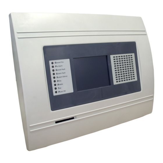
1. INTRODUCTION 1.1 General Description IRIS is an analogue addressable fire panel with maximum coverage of 96 zones and connecting 1 to 4 loops. The panel supports two communication protocols: System Sensor series 200/500 (Loop SS) and Teletek Electronics (Loop TTE) according the type of used devices. In the configuration of the IRIS panel can be implemented both Loops SS and TTE at the same time. -
Page 6: General Technical Specifications
- Main Power Supply: ~230V ±10% - Frequency: 50/ 60Hz - Electrical output: ATTENTION: Do not instal the fire panel near power electromagnetic fields (radio equip- ment, electric motors, etc.)! Addressable Fire Panel IRIS - Installation and Programming Manual... - Page 7 - Outputs: 0,3A, PTC Type - Battery: 7.5A, PTC Type List of the additional components, included in the set of the fire panel IRIS: Resistor 10K ±5%, 0,25W Anchor 6х30mm Fuse 2А, T type 5x20mm (for the mains power supply) Screw М4х40 Cross slot DIN7985...
-
Page 8: Installation
(see Figure 17) BUT DO NOT apply the main electrical supply at this stage. • Position the battery in an upright position and fix the metal clamp - Figure 10. Figure 4 Figure 5 Addressable Fire Panel IRIS - Installation and Programming Manual... -
Page 9: Flush Mounting (Option)
2.1.2 Flush Mounting (option) • Analogue-addressable fire panel IRIS is provided for flush mounting. The accessory set contains two special hangers (see Figure 7) for flushed wall mounting of the fire alarm panel on 25 mm thick drywall. • Use given on Figure 6 dimensions to outline and to cut the mounting hole in the drywall. -
Page 10: System Components
Clamp for supporting the main power Mains power supply opening. supply cable. Figure 10. Configuration of the basic modules in the system. Addressable Fire Panel IRIS - Installation and Programming Manual... - Page 11 2.2.3 Output Module (I/O Module) and 4 Relay Module The I/O Module (Figure 11) is a basic part of the fire panel IRIS, see the description of the terminals below. The 4 Relay Module is integrated onto the I/O Module and has 4 relays with programmable relay outputs.
- Page 12 0,3A. Before connecting the last sounder in the circuit, parallel to it must be added resistor 10k. Figure 13. Connecting of sounders. Addressable Fire Panel IRIS - Installation and Programming Manual...
-
Page 13: Loop Controller
2.2.5 Loop Expander The IRIS fire panel operates with two loop controllers: Loop SS (System Sensor communication protocol) and Loop TTE (Teletek Electronics communication protocol). The Loop Controller (Figure 14) realizes the connection between the I/O Module and devices connected to the communication line. -
Page 14: Maximum Permissible Cable Length
(Note: In case of using addressable base IRIS ligth B24A, the total amount for I includes: the maximal current con- sumption in alarm mode of 15 devices with base IRIS ligth B24A, and for the rest of the devices with base IRIS ligth B24A - the total consumption in stand-by mode.) is the necessary length of the cable for the loop. - Page 15 Isolator Isolator module module Figure 16. Example for connecting of detectors and call points to a loop expander. The maximum number of devices between two isolator modules is 30! Addressable Fire Panel IRIS - Installation and Programming Manual...
-
Page 16: Main Power Source
Input for connecting the Fault output of the external power supply. +13.8V External power supply input. Before the mains supply is switched on, check the correct connection of each loop, sounder or any other input or output. Addressable Fire Panel IRIS - Installation and Programming Manual... -
Page 17: Connecting Of The Battery
If the battery is new it will take a few hours before its complete charging! The charging of the accumulator battery is done at maximum current I=2A and charging voltage U < 13,8V. Addressable Fire Panel IRIS - Installation and Programming Manual... -
Page 18: Main Board Schematic
2.4 Network connection diagram It is possible to connect some individual IRIS fire panels in a network by means of a HUB and TCP/IP protocol - Figure 20. A supervisor PC, which could follow the current status of the individual fire panels, monitors the current panel state. -
Page 19: Programming
The APPENDIx E on page 58. 3.0.3 Default language The fire panel IRIS can support different languages of the programming menus. The factory default setting of the language is in English. You can change the language after the initial power-up as enter in sequence: Access 1 →... -
Page 20: Access Codes
MENU - Moves back to the Main Screen of the related access level. All access codes could be viewed and edited in the “Access Codes“ submenu based in “Panels“ menu, see also item 3.7.1, page 36. Addressable Fire Panel IRIS - Installation and Programming Manual... - Page 21 Output Delay Introducing √ View LOG View the LOG-file √ √ √ Test Testing √ √ Disable Disable Introducing √ Software Revision View the software revision √ Calibration Calibration of the Display Addressable Fire Panel IRIS - Installation and Programming Manual...
-
Page 22: Devices
Button “Save” is for quick saving of the entered information. With the button “Exit” in the bottom left corner the user/installer can easy move one step back on the previous screen. Addressable Fire Panel IRIS - Installation and Programming Manual... -
Page 23: Periphery Devices
3.3 Devices The addressable fire panel IRIS light supports periphery and loop devices. All “functional modules” connected to the control panel configuration are defined as Periphery Devices, and have special programming and setting. The Main board is not a periphery device. All addressable devices connected to loop expaneder are defined as Loop Devices. -
Page 24: Adding A New Periphery Device To The Panel
Choose the SAVE button to add the new periphery devices to the panel configuration. If a device is not re- sponding you can remove it as choosing the REMOVE button. Fig. Screen 5 PSU Parameters (Power source) Fig. Screen 6 – OUT (I/O module + 4 Relay Expander Module) Addressable Fire Panel IRIS - Installation and Programming Manual... -
Page 25: Loop Devices
The “SAVE” button can be used for fast configuration of the device. Following this command, the panel sets up all detected loop and periphery devices by default. New devices only are configured under this command. The “RESTORE DEFAULTS” command deletes all system parameters. Addressable Fire Panel IRIS - Installation and Programming Manual... -
Page 26: Confirm Change Button
(FIRE) - Fig. Screen 11, is performed by pressing of the respec- tive button and entering of the desired value by means of an additional keypad displayed on the screen. Addressable Fire Panel IRIS - Installation and Programming Manual... - Page 27 Switches between capital and small letters. Switches to numbers. Space. Deletes numbers or letters. Confirmation of the entered numbers or letters. Fig. Screen 11. Additional settings for System Sensor devices. Addressable Fire Panel IRIS - Installation and Programming Manual...
- Page 28 New devices only are configured under this command. The “RESTORE DEFAULTS” command deletes all system parameters. On Fig. Screen 12 is given the general view of the submenu for new loop Teletek Electronics devices for LOOP TTE (SensoIRIS MCP150 in the example).
- Page 29 * There are 3 temperature classes for operation: A1R (58º,RoR), A2S (60º), BS (75º). To change the class simple press the active button next to the field and choose a new level from the list. To save the new setting press the “SAVE” button on the main screen. Addressable Fire Panel IRIS - Installation and Programming Manual...
- Page 30 Important Note: The alarm must remain active during the programmable period of time in order to generate an alarm event from the panel. If the detector restores its normal state prior to time-out, the panel shall not generate alarm. Addressable Fire Panel IRIS - Installation and Programming Manual...
-
Page 31: Zones
Choose in sequence from the Main menu screen System - Programming - Zones. The IRIS light addressable fire panel avails of 96 zones. The FIRE and PREALARM conditions are indicated by the help of the LED of the corresponding zone. In the PREALARM condition - the respective zone LED blinks and a warning message is displayed on the screen. -
Page 32: Inputs
Note: It is possible to enter addresses only of loop devices, which are INPUT type: detectors, call points, input- outputs modules! If the device if not an INPUT type a message is shown: “This device can not be used as Input!” Addressable Fire Panel IRIS - Installation and Programming Manual... - Page 33 - INPUT Number. Enter a number from 1 to 128. - PANEL/REPITER Number. Enter a number from 1 to 32. All changed parameters are confirmed and saved by pressing the APPLY button in the upper left corner of the screen. Addressable Fire Panel IRIS - Installation and Programming Manual...
-
Page 34: Outputs
All changed parameters are confirmed and saved by pressing the APPLY button in the upper left cor- ner of the screen. 3.6.3 Output Delay The delay can be within the interval 0–600 sec. Addressable Fire Panel IRIS - Installation and Programming Manual... -
Page 35: Output Active Status (Polarity)
3.6.7 Menu for selection of the inputs, controlling the outputs Fig. Screen 18 All changed parameters are confirmed and saved by pressing the APPLY button in the upper left cor- ner of the screen. Addressable Fire Panel IRIS - Installation and Programming Manual... -
Page 36: Panel
There must be at least one code in the system with an access code 3! The pro- gram disallows editing a level of access (3) if it is the only one! Addressable Fire Panel IRIS - Installation and Programming Manual... -
Page 37: Network
From Network Settings menu can be programmed additionally panel IP, Netmask and IP-number of the Router, as and to be seen the panel MAC-address after choosing the MORE button - see Fig. Screen 21A. Fig. Screen 21A Addressable Fire Panel IRIS - Installation and Programming Manual... -
Page 38: Panels Menu
• Repeat Fire Protection - Follows the Fire Protection output status of the remote panel including the de- lays. All changed parameters are confirmed and saved by pressing the APPLY button in the upper left corner of the screen. Addressable Fire Panel IRIS - Installation and Programming Manual... -
Page 39: Sounders Mode
• Zonal - Only the sounder of the zones with alarm condition will be activated. Fig. Screen 24 - Choosing a Sounders Mode. All changed parameters are confirmed and saved by pressing the APPLY button in the upper left cor- ner of the screen. Addressable Fire Panel IRIS - Installation and Programming Manual... -
Page 40: Call Points Mode
Here the Installer can set a common time delay for activation for all outputs (from 0 to 60 seconds). By default a 30 seconds time delay is set in the system. See also APPENDIX E - “Two steps of alarming” working algorithm. Addressable Fire Panel IRIS - Installation and Programming Manual... -
Page 41: Maintenance
Choose the button “Date” from the Maintenance Menu to set the current date - Fig. Screen 28. Use the APPLY button to confirm the settings. The desired date can be set with the buttons for se- lecting the day, month and year. Fig. Screen 28. Addressable Fire Panel IRIS - Installation and Programming Manual... -
Page 42: Daytime Mode
The Day time operating mode is indicated with icon All changed parameters are confirmed and saved by pressing the APPLY button in the upper left cor- ner of the screen. Addressable Fire Panel IRIS - Installation and Programming Manual... -
Page 43: Sounder Delay
In Schedule mode the initial hour and minutes (the time when the delay is activated) and the end hour and minutes (the time when the delay is deactivated) are introduced. The times are set for every day of the week. During turned on “Delay” the LED is active. Addressable Fire Panel IRIS - Installation and Programming Manual... -
Page 44: Fire Output Delay
Choose “View Log” from the Maintenance Menu to enter in a screen for viewing the happened events in the system. The addressable fire panel IRIS light can show maximum 10 000 events, which could be viewed by date or number - Fig. Screen 33. -
Page 45: Testing
4.7 Testing The addressable fire panel IRIS light has an option for testing of zone functioning and the LED-indication of the panel. To make a test, choose the “Test” button from Programming Menu - Fig. Screen 26. On the displayed screen the user/ installer could choose which test to perform - zone or LED-indication testing - Fig. -
Page 46: Disabling
Programming. Note: From the disabling menu you can directly enter in the loop devices configu- ration menu (Fig. Screen 8) /zone configuration menu (Fig. Screen 12) as choose “Loop Devices” / “Zones” button (Fig. Screen 32). Addressable Fire Panel IRIS - Installation and Programming Manual... -
Page 47: Outputs Disabling
From the menu for disabling introduction - Fig. Screen 35, the user/installer can disable or enable the moni- tored outputs of the IRIS light fire panel - Sounder, Fire Brigade, Fire Protection and Fire Routing - Fig. Screen 38. Use the APPLY button to confirm your choice. - Page 48 The message “Calibration Unsuccessful!!!” will be displayed if the calibration has been unsuccessful, the newly introduced data will be ignored and after pressing of any part of the display, the program returns to the main menu. Fig. Screen 40. Addressable Fire Panel IRIS - Installation and Programming Manual...
-
Page 49: Power Save Backlight Mode
Use the APPLY button to confirm you choice. If the Backlight Save Mode is Enabled the LCD Backlight will switch off after 60 sec when the LCD Touch screen display is not used. You you can switch on the backlight by simple pressing the touch screen. Addressable Fire Panel IRIS - Installation and Programming Manual... -
Page 50: Status Line
Used for accessing the alarm review window. The button contains a counter of the current alarms in the panel. • Faults Access Button Used for accessing the error review window. • Warnings Access Button Used for accessing the warnings review window. 5.2 Panel Status Icons Fig. Screen 44. Addressable Fire Panel IRIS - Installation and Programming Manual... -
Page 51: Panel Mode Icon
The fire extinguishing is disabled - disabled output. Grey The fire extinguishing output is delayed - delay is running prior to activation (programmable for every zone). The icon blinks and the countdown time until (Blinks) activation is displayed. Addressable Fire Panel IRIS - Installation and Programming Manual... -
Page 52: Messages
The “Evacuate” button is activated only in access levels 2 and 3. After it is pressed, the sounder and the pro- grammable outputs will be activated, the “General Fire” LED lights up and a warning message is displayed. Note: The System Button is described in details in part Programming. Addressable Fire Panel IRIS - Installation and Programming Manual... -
Page 53: Appendix
New Loop Device Found Loop Short Short-circuit in the loop. Loop Break Interrupted loop. Loop Zero Address There is a device without address number (a device with addres 0 is applied). Addressable Fire Panel IRIS - Installation and Programming Manual... - Page 54 Addressable Fire Panel IRIS - Installation and Programming Manual...
- Page 55 Addressable Fire Panel IRIS - Installation and Programming Manual...
- Page 56 2. Call Points • SensoIRIS MCP150 - Call point with built-in isolator 3. Основи • IRIS light B24A - Addressable fire base for connecting of SensoMAG conventional detectors. 4. Modules • SensoIRIS MIO - Inputs - Outputs module • SensoIRIS MCZ (ZONE MONITOR MC) - Conventional zone module •...
- Page 57 Appendix D - General Menu Structure Addressable Fire Panel IRIS - Installation and Programming Manual...
- Page 58 www.teletek-electronics.com Address: Srebarna 14А, 1407 Sofia, Bulgaria Tel.: (+359 2) 9694 700, Fax: (+359 2) 962 52 13 e-mail: info@teletek-electronics.bg...
Need help?
Do you have a question about the IRIS and is the answer not in the manual?
Questions and answers