
Related Manuals for Teletek electronics SIMPO


Summary of Contents for Teletek electronics SIMPO
- Page 1 SIMPO - BASIC INFORMATION Fire alarm panel SIMPO Page 1 of 48 Simpo Addressable Panel...
- Page 2 SIMPO - BASIC INFORMATION Addressable Fire alarm Panel: Simpo 1.) Technical specification Loops: • Up to 2 – both built in the main PCB. The second is with additional PCB mounted over the main PCB (on special terminals). • Earth fault detection – enabling and disabling from the panel (Software).
- Page 3 SIMPO - BASIC INFORMATION • Access level 4 is only for authorized personal, which has knowledge to update the panel’s software. Access can be obtained by means of special tool (screwdriver, mechanical key-switch or external programmer). Inputs: • Input 1 – Alarm Confirmation - meets VdS 2540 •...
- Page 4 Repeater: • Each regular panel Simpo can be set as repeater from it’s system menu. • There will be a special Low-price and more compatible Just repeater panel with only repeating functionality. It will be in smaller box and will have just LCD screen, LED indication and buttons for RESET, EVACUATION, SILENCE ALARM and SILENCE BUZZER.
- Page 5 SIMPO - BASIC INFORMATION Box: • Metal enclosure box • Surface mount • Dimensions: L365xH412xW78 Standards: • Designed according to EN-54/2, EN-54/4 • The panel will be certified according to EN-54/2 Packing: • Plastic bag • Carton box – white, without printings •...
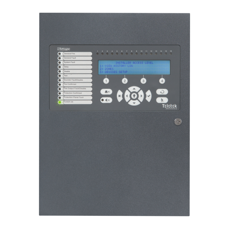
- Page 6 SIMPO - BASIC INFORMATION 2.) Programming 2.1) Front Panel Description 2.1.1) Access codes To access the Programming and Maintenance Menus it is necessary to enter a valid access code. There are 3 access codes programmed by default: - USER Access – no code needed...
- Page 7 SIMPO - BASIC INFORMATION If access 2 or 3 is active and the installer do not perform action for 30 seconds, the panel automatically returns in access level 1. 2.1.2) LED indication Description LED Name Activation Action Buzzer Action Colour...
- Page 8 SIMPO - BASIC INFORMATION If there is a fault in the Pulse Sound Fire Output Fault Constantly ON Yellow fire output circuit. Protection If Input 2 is activated. Constantly ON One Pulse Yellow Confirmed See page 3 Sound If Input 2 is activated.
- Page 9 SIMPO - BASIC INFORMATION starts fire condition (*Level 1 just 1*,2,3 Constantly overrides the delays if fire condition is active) Illuminates all possible indication on the None LED Test main panel, including the LCD. Entering menus, confirms and saves 1,2,3...
- Page 10 SIMPO - BASIC INFORMATION 2.3) Programming Menu’s Structure (Access Level 2 Maintenance) (Grey is inactive) Page 10 of 48 Simpo Addressable Panel...
- Page 11 SIMPO - BASIC INFORMATION 2.4) Access Level Menus and Initial Screan – the LCD panel is 4 rows, 40 symbols per row. 2.4.1) Starting Screen – the system is performing its initial start and is searching for new devices. S I M P O V e r s i o n 1 .
- Page 12 SIMPO - BASIC INFORMATION After this operation on the screen will appear: M A I N T E N A N C E A C C E S S L E V E L 1 0 ) S O F T .
- Page 13 SIMPO - BASIC INFORMATION Z O N E S V I E W L O G T o t a l E n t r i e s : n n n n n A l a r m...
- Page 14 SIMPO - BASIC INFORMATION Y E S After erasing the panel returns to the Clearing Memory LOG window with events counter=00000. - Submenu PRINT: allows to print entire log or part of the log. Printing options: i n t L O G ...
- Page 15 SIMPO - BASIC INFORMATION Zone can be selected by pressing enter. To scroll between all zones the user has to use the arrow buttons: Z O N E : D I S A B L E D F L O O R...
- Page 16 SIMPO - BASIC INFORMATION The display will stay for 5 seconds and will return to the previous screen or if in less then 5 seconds ESC is pressed will do the same. - Submenu Test/Stop Test: menu for Testing zones.
- Page 17 SIMPO - BASIC INFORMATION Z O N E : D I S A B L E D F L O O R Z O N E : D I S A B L E D F L O O R ...
- Page 18 SIMPO - BASIC INFORMATION Delays T2 menu is for settind delays for Sounder and Fire brigade outputs. The delays are up to 540 seconds – 9 minutes. Default delays are 60 seconds. E N T E R D E L A Y S...
- Page 19 SIMPO - BASIC INFORMATION D : 2 5 0 L : 1 N O N E 1 0 2 D : 0 0 1 Z 0 2 L : 2 O P T I C A L E N A B L E D...
- Page 20 SIMPO - BASIC INFORMATION D : 2 5 0 Z 0 1 L : 1 M C P 1 5 0 E N A B L E D R O O M 1 0 0 1 0 2 D : 0 0 1...
- Page 21 SIMPO - BASIC INFORMATION D : 2 5 0 Z 0 1 L : 1 M C P 1 5 0 E N A B L E D R O O M 1 0 0 1 0 2 D : 0 0 1...
- Page 22 SIMPO - BASIC INFORMATION - Editing devices: If edit menu is pressed the following screens will appear: - Optical Detector D : 0 2 7 L : 2 O P T I C A L Z O N E : 0 4...
- Page 23 SIMPO - BASIC INFORMATION D : 0 2 9 C O M B I N E D Z O N E : 0 4 N A M E : _ _ _ _ _ _ _ _ _ _ _ _ _ _ _ _ _ _ _ _ _ _ _ _ _ _ _ _ _ _ _ _ _ _ _ _ _ _ _ _...
- Page 24 SIMPO - BASIC INFORMATION L : 2 S O U N D E R Z O N E : 0 4 N A M E _ _ _ _ _ _ _ _ _ _ _ _ _ _ _ _ _ _ _ _ _ _ _ _ _ _ _ _ _ _ _ _ _ _ _...
- Page 25 SIMPO - BASIC INFORMATION GENERATES TYPE BEHAVIOR FIRE Latched RESET Unlatched MESSAGE WARNING Unlatched SILENCE BUZZZER Unlatched SILENCE ALARM Latched EVACUATE Event RESET: G E N E R A T E S : R E S E T D E L A Y :...
- Page 26 SIMPO - BASIC INFORMATION All events and types are placed in the table below: ACTIVATION TYPE DEVICE BEHAVIOR INPUT GROUP Latched/Unlatched FIRE ZONE ZONE GROUP COMMON Latched/Unlatched FAULT ZONE ZONE GROUP COMMON SYSTEM Latched PREALARM ZONE ZONE GROUP COMMON Latched/Unlatched...
- Page 27 SIMPO - BASIC INFORMATION A C T I V A T I O N : S I L E N C E T Y P E : B U Z Z E R D E L A Y : 6 0 0...
- Page 28 SIMPO - BASIC INFORMATION - menu ADDRESSING has 3 submenus Set Address, Change Address and Start Self Addressing (in the future there will be 4-th menu – Auto Addressing) I N S T A L L E R A C C E S S L E V E L 4 .
- Page 29 SIMPO - BASIC INFORMATION - Подменю Self Addressing ще изглежда по следният начин и ще има следните функции: S E L F A D D R E S S I N G A D D D E V I C E . . .
- Page 30 SIMPO - BASIC INFORMATION I N S T A L L E R A C C E S S L E V E L S e l e c t P a n e l ! ( L O O P...
- Page 31 SIMPO - BASIC INFORMATION The status of the output can be DISABLED and ENABLED. - Submenu Relay Outputs: R E L A Y O U T P U T S S e l e c t...
- Page 32 SIMPO - BASIC INFORMATION Confirmation screen: I n s t a l l e r A c c e s s C o d e U s e t h e b u t t o n s C O N F I R M...
- Page 33 SIMPO - BASIC INFORMATION D a y : T h u r s d a y N i g h t S t a r t s: 0 0 : 0 0 C H A N G E S E T A L L The BUTTON SET TO ALL will apply the set times to all days of the week.
- Page 34 SIMPO - BASIC INFORMATION Setting Delay: D e l a y S e l e c t u s i n g a n d E n t e r D e l a y : Delay is adjustable with the arrows up to 60 seconds. The default is 30 seconds.
- Page 35 SIMPO - BASIC INFORMATION N e t w o r k S t a t u s : E N A B L E D C H A N G E The name is 40 symbols. Panel number is from 01 to 32. Network is by default disabled. The panels are recognized in the system by panel’s number.
- Page 36 SIMPO - BASIC INFORMATION The states of the panels are Online, New, Empty and Offline. If EDIT is Pressed: T E L E T E K D R U J B A R e c i e v e ( F r...
- Page 37 SIMPO - BASIC INFORMATION Y E S After YES is pressed: S a v i n g C o n f i g u r a t i o n P l e a s e W a i t . . .
- Page 38 SIMPO - BASIC INFORMATION U P D A T E Submenu Update Menu for updating the firmware thru USB flash drive. W o r k U S B a s h i v E U S B O T G...
- Page 39 SIMPO - BASIC INFORMATION A L A R M S : 0 0 5 F A U L T S D I S A B L E M E N T S M O R E > > The P:02 will appear only if the event is from a network panel.
- Page 40 SIMPO - BASIC INFORMATION R O O M N o : 4 2 5 F L O O R S A T U R D A Y 0 1 - 0 3 - 2 0 1 1...
- Page 41 SIMPO - BASIC INFORMATION O P T I C A L 0 0 1 F I R E Z : 0 4 D : 0 5 6 0 0 2 F I R E Z : 0 4 D : 0 5 7 O P T I C A L O P T I C A L ...
- Page 42 SIMPO - BASIC INFORMATION - Loop Device Disabled indication: 0 0 1 Z O N E D I S A B L E D Z : 0 5 0 0 3 D E V D I S A B L E D...
- Page 43 SIMPO - BASIC INFORMATION S A T U R D A Y 0 1 - 0 3 - 2 0 1 1 0 0 : 0 0 Fault Output and Sounder Outputs indication is with the same structure. - Zone Test indication: ...
- Page 44 SIMPO - BASIC INFORMATION - Faults Indication: 0 0 1 F A U L T M A I N P A N E L R A M E R R O R 0 0 2 F A U L T...
- Page 45 SIMPO - BASIC INFORMATION L O O P : S A T U R D A Y 0 1 - 0 3 - 2 0 1 1 0 0 : 0 0 0 1 9 F A U L T ...
- Page 46 SIMPO - BASIC INFORMATION General fault LED concerns all general faults, System Fault LED concerns System faults. System fault LED occurs in case of CPU crash. - System Silence Indication: LED indication for system silence will occure if Silence alarm button is pressed during alarm.
- Page 47 SIMPO - BASIC INFORMATION Charger Fault Chamber Fault Flash Error Loop Device Type Error Battery Low Loop Device Fault Battery Loss Clean Me Now AC Loss Loop Device Input Fault Earth Fault Loop Device Output Fault Fault Routing – Fault...
- Page 48 SIMPO - BASIC INFORMATION 4.) Panel’s Structure 4.1) Box plan: Page 48 of 48 Simpo Addressable Panel...