Table of Contents
Advertisement
Quick Links
Advertisement
Chapters
Table of Contents

Related Manuals for Oracle Database Appliance


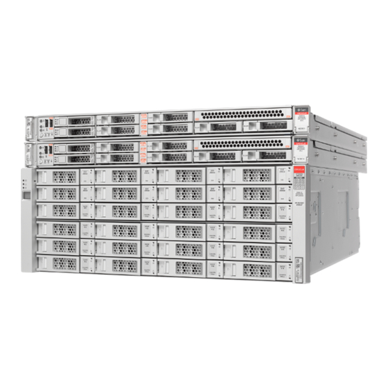
Summary of Contents for Oracle Database Appliance
- Page 1 Oracle Database Appliance Service Manual Part No: E69614-01 February 2016...
- Page 3 Oracle. Oracle Corporation and its affiliates will not be responsible for any loss, costs, or damages incurred due to your access to or use of third-party content, products, or services, except as set forth in an applicable agreement between you and Oracle.
- Page 4 Oracle Corporation et ses affiliés déclinent toute responsabilité ou garantie expresse quant aux contenus, produits ou services émanant de tiers, sauf mention contraire stipulée dans un contrat entre vous et Oracle. En aucun cas, Oracle Corporation et ses affiliés ne sauraient être tenus pour responsables des pertes subies, des coûts occasionnés ou des dommages causés par l’accès à...
-
Page 5: Table Of Contents
Ethernet Port Indicators ................ 25 2 Preparing Oracle Database Appliance for Service ........ 27 Preparing Oracle Database Appliance X3-2/X4-2/X5-2 for Service ...... 27 Preparing Oracle Database Appliance (Original Version) for Service ....... 28 Component Replacement Policy – CRUs and FRUs ........ 28 Safety Information ................. 30 Required Tools .................. 30... - Page 6 Components .................... 39 Oracle Database Appliance X3-2/X4-2/X5-2 Storage Shelf Hot-Swappable Components .................... 40 Replacement Procedures (CRU) ............... 40 Oracle Database Appliance (Original Version) Hot-Swappable Components ..... 47 Servicing Storage Drives and Boot Drives (CRU) ........ 48 Servicing Fan Modules (CRU) .............. 54 Servicing Power Supplies (CRU) ............. 57 4 Servicing CRUs That Require Server Node Power Off ........ 61 Servicing Oracle Database Appliance X3-2/X4-2/X5-2 CRUs ........ 61...
- Page 7 Contents Returning Oracle Database Appliance (Original Version) to Operation .... 139 Installing the Server Node Top Cover ............ 139 Installing a Server Node Into the System Chassis ........ 140 Powering On Oracle Database Appliance (Original Version) ...... 142 7 Server Node Diagnostic Tools and Resetting the Service Processor ... 145 Server Node Diagnostic Tools ................
- Page 8 Oracle Database Appliance Service Manual • February 2016...
-
Page 9: Preface
Documentation Accessibility For information about Oracle's commitment to accessibility, visit the Oracle Accessibility Program website at http://www.oracle.com/pls/topic/lookup?ctx=acc&id=docacc. Access to Oracle Support Oracle customers have access to electronic support through My Oracle Support. For information, visit or visit http://www.oracle.com/pls/topic/lookup?ctx=acc&id=info if you are hearing impaired. - Page 10 Contributors Contributors Ralph Woodley, Doug Archambault, Kevin Deihl, Kyle Walker Change History The following lists the release history of this documentation set: February 2016. Initial publication. ■ Oracle Database Appliance Service Manual • February 2016...
-
Page 11: Overview Of System Status Indicators And Leds
■ Oracle Database Appliance X3-2 ■ Oracle Database Appliance original version (also referred to as "version 1" or "V1") ■ The following sections in this chapter describe system status indicators and LEDs: “Oracle Database Appliance X5-2 Status Indicators” on page 11 ■... -
Page 12: Storage Shelf Status Indicators
Oracle Database Appliance X5-2 Status Indicators The links below take you to topics outside of the Oracle Database Appliance library to Note - the Oracle Server X5-2 documentation library. Use your browser's Back button to return to the Oracle Database Appliance library. - Page 13 ■ Off – Normal operation. ■ Fast blink – This LED blinks to help locate the system. Operators can turn this indicator on and off remotely using Oracle ILOM. ■ Pressing this button toggles the fast blink on or off.
-
Page 14: Oracle Database Appliance X3-2/X4-2 Status Indicators
These topics describe Oracle Database Appliance X3-2 and Oracle Database Appliance X4-2 server node status indicators (LEDs). The links in the following table take you to topics outside of the Oracle Database Note - Appliance library to the Sun Server X3-2 and Sun Server X4-2 documentation libraries. Use your browser's Back button to return to the Oracle Database Appliance library. -
Page 15: Storage Shelf Status Indicators
Server Node Motherboard Status Indicators Server Node Motherboard Status Indicators Storage Shelf Status Indicators Storage shelves are supported with Oracle Database Appliance X3-2/X4-2. They include controls and indicators on the front panel, hard drives, SSD drives, power supplies, and SAS I/ O modules. - Page 16 ■ Off – Normal operation. ■ Fast blink – This LED blinks to help locate the system. Operators can turn this indicator on and off remotely using Oracle ILOM. ■ Pressing this button toggles the fast blink on or off.
-
Page 17: Oracle Database Appliance (Original Version) Status Indicators
Lights green to indicate host SAS link activity. (x4 per port): green Oracle Database Appliance (Original Version) Status Indicators This section describes the status indicators for the original version Oracle Database Appliance. “Server Node Status Indicators” on page 17 ■ “Server Node Fan Indicators” on page 20 ■... - Page 18 ■ Off – No power is supplied to the SP or it is not functional. ■ Amber – When lit indicates an SP fault. ■ Green – When steady on indicates that Oracle ILOM is fully functional. If blinking, POST diagnostics are running, Oracle ILOM is booting, or firmware is updating.
- Page 19 Oracle Database Appliance (Original Version) Status Indicators Callout Indicator/LED: Color State Meaning reset by Oracle ILOM. If it times out, the amber LED is lit and the green LED is extinguished. Ready to Remove: blue ■ Off – Normal operation.
-
Page 20: Server Node Fan Indicators
The LEDs on the fan modules are not lit amber on initial system power-on. The fan Note - amber LED only lights if Oracle ILOM detects a failure that indicates a faulty fan module or a missing fan that should be installed. -
Page 21: Storage And Boot Drive Status Indicators
■ Off – The drive is powered off or the installed drive is not recognized by the system. Power Supply Status Indicators There are three status LEDs on each power supply for Oracle Database Appliance (original version), as shown in the following table. Chapter 1 • Overview of System Status Indicators and LEDs... -
Page 22: Rear Server Node Status Indicators
■ Off – The power supply is unplugged or turned off. Rear Server Node Status Indicators Each server node in Oracle Database Appliance (original version) has four summary status LEDs that are located on its back panel, as shown in the following table. - Page 23 This LED indicates the operational state of the chassis. This LED can be in the following states: ■ Off – AC power is not present or the Oracle ILOM boot has not completed. ■ Standby blink – Standby power is on and Oracle ILOM can be accessed, but full chassis power is off.
-
Page 24: Server Node Internal Leds
(OS), or 3) the system host is running the OS. Server Node Internal LEDs The following section describes the internal LEDs for Oracle Database Appliance (original version). Each server node contains the following internal LEDs: A super capacitor (located on the motherboard) provides power to light the server node... -
Page 25: Ethernet Port Indicators
Oracle Database Appliance (Original Version) Status Indicators Ethernet Port Indicators Each server node in Oracle Database Appliance (original version) has two host Ethernet ports (NET0 and NET1) and an SP network management port (NET MGT). Each of these has two LEDs that indicate link activity and port speed. - Page 26 Oracle Database Appliance Service Manual • February 2016...
-
Page 27: Preparing Oracle Database Appliance For Service
Preparing Oracle Database Appliance X3-2/X4-2/X5-2 for Service This section describes preparing Oracle Database Appliance X3-2, Oracle Database Appliance X4-2, and Oracle Database Appliance X5-2 for service. If you have Oracle Database Appliance (original version), go to “Preparing Oracle Database Appliance (Original Version) for Service”... -
Page 28: Preparing Oracle Database Appliance (Original Version) For Service
Preparing Oracle Database Appliance (Original Version) for Service This chapter describes how to prepare Oracle Database Appliance (original version) for servicing. If you have Oracle Database Appliance X3-2, Oracle Database Appliance X4-2, or Oracle Database Appliance X5-2, go to “Preparing Oracle Database Appliance X3-2/X4-2/X5-2 for Service”... - Page 29 Preparing Oracle Database Appliance (Original Version) for Service A part designated as a CRU can be replaced by a person who is not an Oracle-qualified ■ service technician. The following table lists replaceable components, their service designation (CRU or FRU), and the system power policy related to servicing the component.
-
Page 30: Safety Information
■ Obtaining the Chassis Serial Number To obtain support for Oracle Database Appliance (original version), you need to report your product serial number. The product serial number is located on an RFID tag on the front of the system and on the Customer Information Sheet that is included with the system. -
Page 31: Shutting Down A Server Node And Powering Off The System
Data loss. To avoid data loss and file system corruption, always use a graceful Caution - shutdown unless it is an emergency. To use Oracle ILOM to shut down a server node, ensure that you have performed its Note - initial configuration as described in "Connecting and Configuring Oracle ILOM" in the Oracle Database Appliance Getting Started Guide. - Page 32 When the server node is shut down, the Power/OK LED [2] on the server node's front panel flashes, indicating that the server node is in standby power mode. To shut down a server node using the Oracle ILOM, perform one of the following: ■...
- Page 33 Using the Oracle ILOM CLI: ■ a. Log in to Oracle ILOM using an ssh client. Type: sp_ip_address ssh username@ Where username is a user account name with Reset and Host Control (r) privileges and sp_ip_address is the IP address of the server node service processor.
-
Page 34: Performing Electrostatic Discharge And Antistatic Prevention Measures
■ components) Removing Server Nodes From the System Chassis You must remove the Oracle Database Appliance (original version) server node from the chassis to remove or replace internal server node components. Remove a Server Node From the System Chassis The removal procedure is the same for both server nodes. Note that you do not need to remove the entire system chassis from the rack to perform service procedures on a server node. -
Page 35: Removing The Server Node Top Cover
Slide the server node to the rear and lift it out of the system [2]. Removing the Server Node Top Cover To gain access to a most of Oracle Database Appliance (original version) server node's internal components, you must remove the server node's top cover. -
Page 36: Removing The Middle Section Of The System Top Cover
Removing the Middle Section of the System Top Cover To gain access to the Oracle Database Appliance (original version) power distribution board and the disk midplane board you must remove the middle section of the system's top cover. Remove the Middle Section of System Top Cover Power down the server nodes and remove the power cords from the power supplies. - Page 37 Hazardous voltage present. Never run the system with the middle section of the Caution - system top cover removed. Equipment damage. Install the system top cover properly before starting the system. Caution - Chapter 2 • Preparing Oracle Database Appliance for Service...
- Page 38 Oracle Database Appliance Service Manual • February 2016...
-
Page 39: Servicing Crus That Do Not Require System Power Off
Oracle Database Appliance X3-2/X4-2/X5-2 Server Node Hot- Swappable Components This section describes replacing hot-swappable components for the Oracle Database Appliance X3-2, Oracle Database Appliance X4-2, and Oracle Database Appliance X5-2 for service. If you have Oracle Database Appliance (original version), go to “Oracle Database Appliance (Original Version) Hot-Swappable Components”... -
Page 40: Oracle Database Appliance X3-2/X4-2/X5-2 Storage Shelf Hot-Swappable Components
Oracle Database Appliance X3-2/X4-2/X5-2 Storage Shelf Hot-Swappable Components Refer to the following table for hot-swap component instructions for your appliance. The links in the following table take you to instructions outside of the Oracle Database Note - Appliance library to the Sun Server X3-2, Sun Server X4-2, and Oracle Server X5-2 documentation libraries. - Page 41 Replace a Storage Shelf HDD or SSD “Replace a Storage Shelf HDD or SSD” on page 41 ■ “Replace a Storage Shelf Power Supply” on page 43 ■ “Replace a Storage Shelf I/O Module” on page 45 ■ Replace a Storage Shelf HDD or SSD Locate the failed drive on the front of the chassis.
- Page 42 Example showing the DE2-24C: Open the drive lever on the replacement drive. While constantly pushing toward the pivot point of the lever, slide the drive fully into the chassis slot. Example showing the DE2-24P: Oracle Database Appliance Service Manual • February 2016...
- Page 43 Replace a Storage Shelf Power Supply Example showing the DE2-24C: Replace a Storage Shelf Power Supply The storage shelf and the storage expansion shelf each have two power supplies. Indicators (LEDs) on the power supplies indicate their operation state. The power supplies are redundant and one can be replaced while the appliance is running. Chapter 3 •...
- Page 44 Ensure the power supply on/off switch is in the "O" off position. Disconnect the power cord tie strap from the power cord, and unplug the power cord from the power supply. Oracle Database Appliance Service Manual • February 2016...
- Page 45 Replace a Storage Shelf I/O Module Release the lever/ejection arms. Pull the power supply module out of the chassis. Open the lever/ejection arms on the replacement power supply. Slide the replacement power supply module into the chassis. Be careful to not bend the pins. Close the lever/ejection arms.
- Page 46 Replace a Storage Shelf I/O Module Example showing the DE2-24P: Example showing the DE2-24C: Callout Description I/O module 1 (top) I/O module 0 (bottom) Oracle Database Appliance Service Manual • February 2016...
-
Page 47: Oracle Database Appliance (Original Version) Hot-Swappable Components
Oracle Database Appliance (Original Version) Hot- Swappable Components This section describes replacing hot-swappable components for the Oracle Database Appliance (original version) for service. If you have Oracle Database Appliance X3-2, Oracle Database Chapter 3 • Servicing CRUs That Do Not Require System Power Off... -
Page 48: Servicing Storage Drives And Boot Drives (Cru)
Servicing Storage Drives and Boot Drives (CRU) Oracle Database Appliance (original version) has 24 storage drives, located in the front of the chassis, and each server node has 2 boot drives, located in the rear. All storage drives and boot drives are hot-swappable. - Page 49 Server Node boot drives. Each appliance server node contains two boot drives that are installed in the back of Oracle Database Appliance and identified on the rear drive panel label. Chapter 3 • Servicing CRUs That Do Not Require System Power Off...
-
Page 50: Remove A Storage Drive
[1]. Grasp the latch and open it to a 45 degree angle [2]. b. Using the latch, slowly pull the drive straight out of the drive slot, not c. sideways or vertically. Oracle Database Appliance Service Manual • February 2016... -
Page 51: Install Storage Drive
Install Storage Drive Do not use much force on the latch when removing the drive. Equipment damage. Do not use the latch as an ejector. Do not bend it too far to the Caution - right. Equipment damage. Always replace a drive with another drive to maintain proper Caution - airflow. -
Page 52: Remove A Boot Drive
The amber Service Required LED might be lit. For specific drive locations, see “Storage and Boot Drive Locations” on page Remove the boot drive. To open the drive door, slide the latch to the left. a. Oracle Database Appliance Service Manual • February 2016... -
Page 53: Install A Boot Drive
Install a Boot Drive b. Pull the door open [2]. On the drive you plan to remove, push the storage drive release button to c. open the latch [2]. Grasp the latch and open it to a 45 degree angle [2]. d. ... -
Page 54: Servicing Fan Modules (Cru)
/dev/sdb Servicing Fan Modules (CRU) Each Oracle Database Appliance (original version) server node contains two fan modules. Each fan module contains a single, dual-motor, 80 mm, counter-rotating fan assembly that contains two fans. Each fan module is hot-swappable. For specific information about fan status LEDs, “Server Node Fan Indicators”... - Page 55 Remove a Fan Module ensure proper cooling. When the server node is replaced, its two fans also cool the 24 front disks and provide cooling to the second server node. Equipment damage. If a fan module fails, replace it as soon as possible. Caution - The following topics are covered in this section: “Detecting a Fan Module Failure”...
- Page 56 Align the fan module in the fan door and slide it into the server node. The extender on the side of the fan module pushes the fan door open, allowing the fan module to enter. Apply firm pressure to fully seat the fan module. Oracle Database Appliance Service Manual • February 2016...
-
Page 57: Servicing Power Supplies (Cru)
LEDs. Servicing Power Supplies (CRU) Oracle Database Appliance (original version) is equipped with two hot swappable power supplies. They are redundant, meaning that the system can operate with a single power supply. This allows you to remove and replace a power supply without shutting the system down. - Page 58 LEDs, see “Power Supply Status Indicators” on page Disconnect the power cord from the faulty power supply. Grasp the power supply handle and press the release latch [1]). Oracle Database Appliance Service Manual • February 2016...
- Page 59 Install a Power Supply Pull the power supply out of the chassis [2]. Install a Power Supply Align the replacement power supply with the empty power supply chassis bay. Slide the power supply into the bay until it is fully seated. Chapter 3 •...
- Page 60 Service Required LEDs located on the front of both server nodes ■ REAR HDD/PS/FAN LED located on the front of both server nodes ■ “Storage and Boot Drive Locations” on page 48 for more information about system LEDs. Oracle Database Appliance Service Manual • February 2016...
-
Page 61: Servicing Crus That Require Server Node Power Off
Power Off These sections describe how to service customer-replaceable units (CRUs) for the Oracle Database Appliance that require you to power off the server node. All of these CRUs are located on the server nodes. The servicing of hot-swap components such as the HDDs, SDDs, power supplies, and... -
Page 62: Servicing Oracle Database Appliance (Original Version) Crus
Appliance X4-2, or Oracle Database Appliance X5-2, go to “Servicing Oracle Database Appliance X3-2/X4-2/X5-2 CRUs” on page This section includes information on how to service the following Oracle Database Appliance (original version) CRUs: “Server Node CRU Component Locations” on page 62 ■... -
Page 63: Servicing Memory Modules (Dimms) (Cru)
Battery Servicing Memory Modules (DIMMs) (CRU) Each server node in Oracle Database Appliance (original version) is provisioned with twelve 1333 MHz or 1600 MHz DDR3, 8GB dual rank DIMMs, for a total of 96GB. The server node supports a maximum memory speed of 1333 MHz, even if 1600 MHz DIMMs are installed. - Page 64 Prevention Measures” on page DIMM and CPU Physical Layout Each processor in Oracle Database Appliance (original version) has six DIMM slots numbered D0 through D5. D0 is the closest to the processor and D5 is the farthest. Each slot should contain a 1333 MHz or 1600 MHz DDR3, 8GB dual rank DIMM. No other configurations are supported.
- Page 65 Remove Faulty DIMMs The DDR3 memory modules (DIMMs) are customer-replaceable units (CRUs) and do Note - not require an Oracle-qualified service person for replacement. Prepare the server node for service. Attach an antistatic wrist strap. a. “Performing Electrostatic Discharge and Antistatic Prevention Measures” on page b. ...
- Page 66 LEDs lit or if the server node has been out of the chassis for more then 15 minutes. Callout Description Fault Remind Button Fault Remind Power Good LED (green) b. Note the location of faulty DIMMs. Oracle Database Appliance Service Manual • February 2016...
- Page 67 Remove Faulty DIMMs The amber DIMM fault LEDs light if the adjacent DIMM is faulty. ■ If the DIMM fault LED is off, the DIMM is operating properly. ■ If the DIMM fault Required LED is on (amber), the DIMM is faulty and should be replaced.
- Page 68 Unpack the replacement DIMMs and place them on an antistatic mat. Ensure that the replacement DIMMs match the system requirements. The system supports only 1333 MHz or 1600 MHz DDR3, 8GB, dual rank DIMMs obtained from Oracle. Oracle Database Appliance Service Manual • February 2016...
- Page 69 Install DIMMs For the best performance, if you combine 1333 MHz and 1600 MHz DIMMs in a single system, they should be configured so that P0 and P1 have the same mixture, in the same DIMM slots. For example, in a 1333 MHz system, if you replace P0, D0 with a 1600 MHz DIMM, you should also replace P1, D0 with a 1600 MHz DIMM.
- Page 70 If the notch is not aligned, damage to the DIMM might occur. Repeat Step 3 through Step 5 until all replacement DIMMs are installed. Return the server node to operation. Oracle Database Appliance Service Manual • February 2016...
- Page 71 Power on the server node. “Powering On Oracle Database Appliance (Original Version)” on page 142. Clear the DIMM faults. a. Log in to the server node Oracle ILOM CLI as root. b. To view server node faults, type the following command: -> show /SP/faultmgmt Oracle ILOM lists all known faults.
-
Page 72: Servicing Pcie Risers (Cru)
Advanced ECC corrects up to 4 bits in error on nibble boundaries, as long as they are all in the same DRAM. If a DRAM fails, the DIMM continues to function. To clear a fault once the faulty DIMM has been replaced, type the following in the Oracle ILOM CLI: ->... - Page 73 Remove PCIe Riser From Server Nodes If you are servicing a PCIe card, locate its position on the riser. Disconnect any data cables connected to the cards on the PCIe riser being removed. To disconnect a cable from a PCIe card, press the latch, push in toward the connector, and then pull out to remove the cable.
- Page 74 Tighten the green captive Phillips screw that secures the riser to the d. motherboard [1]. Tighten the three green captive Phillips screws that secure the PCIe riser to e. the chassis [2]. Access these screws from the rear of the server node. Oracle Database Appliance Service Manual • February 2016...
-
Page 75: Servicing Pcie Cards (Cru)
Are you sure you want to clear /SYS/MB/RISER (y/n)? Set 'clear_fault_action' to 'true' Servicing PCIe Cards (CRU) This section describes servicing PCIe cards in Oracle Database Appliance (original version). “PCIe Card Configuration” on page 76 ■ “Remove PCIe Card From PCIe Riser” on page 76 ■... - Page 76 “Removing the Server Node Top Cover” on page Locate the PCIe card in the PCIe riser that you want to remove. See the "Oracle Database Appliance (Original Version) Back Panel" section of the Oracle Database Owner's Guide for the location of the PCIe slots.
- Page 77 Install PCIe Card in PCIe Riser To disconnect a cable from the PCIe card, press the latch, push in toward the connector, and then pull out to remove the cable. Note the location of all cables for reinstallation later. Remove the PCIe riser. “Remove PCIe Riser From Server Nodes”...
- Page 78 Slide the locking bracket down until it engages the PCIe riser locking tab. b. Callout Description Recessed area on the PCIe riser PCIe riser locking tab PCIe card locking bracket Install the PCIe riser. Oracle Database Appliance Service Manual • February 2016...
- Page 79 “Powering On Oracle Database Appliance (Original Version)” on page 142. Clear the PCIe card fault. a. Log in to the server node as root using the Oracle ILOM CLI. b. To view server node faults, type the following command to list all known faults on the system: ->...
- Page 80 Remove the primary PCIe card. Locate the internal PCIe card [1]. a. The internal PCIe card is located next to the rear-mounted disk drives. Disconnect the data cables from the PCIe card [1]. b. Oracle Database Appliance Service Manual • February 2016...
- Page 81 Install Primary HBA PCIe Card in Motherboard There are two data cables that connect the PCIe card to the server node connector that connects to disk drive backplane. Note the location of all cables for reinstallation later. To disconnect the cables from the internal PCIe card, press the latch, push in toward the connector, and then pull out to remove the cable.
- Page 82 142. Clear the primary HBA card fault. a. Log in to the server node as root using the Oracle ILOM CLI. b. To view server node faults, type the following command to list all known faults on the server node: ->...
-
Page 83: Servicing The Server Node Battery (Cru)
The Oracle Database Appliance (original version) battery maintains the date and time for the Oracle ILOM service processor when the server node is removed from the system and, therefore, is powered off. If the server node fails to maintain the proper time when powered off, replace the battery. - Page 84 Otherwise, proceed to the next step. If the service processor is not configured to use NTP, you must reset the Oracle ILOM clock using the Oracle ILOM CLI or the web interface.
- Page 85 Install the server node into the system. “Install Server Node Into System Chassis” on page 140. c. Power on the server node. “Powering On Oracle Database Appliance (Original Version)” on page 142. Chapter 4 • Servicing CRUs That Require Server Node Power Off...
- Page 86 Oracle Database Appliance Service Manual • February 2016...
-
Page 87: Servicing Frus
Version) FRUs” on page Only Oracle authorized service personnel should service FRU components. Most of the links in the following table take you to instructions outside of the Oracle Note - Database Appliance library to the Sun Server X3-2, Sun Server X4-2, and Oracle Server X5-2 documentation libraries. -
Page 88: Updating System_Identifier And/Or Fru Id Information For A Replacement Motherboard Or Disk Backplane
Oracle Database Appliance software and for warranty service. System_Identifier: This is an Oracle ILOM setting maintained in the service processor. By logging in to the Oracle ILOM CLI as root, you can reset this value after replacing a server node's motherboard. - Page 89 /SP system_identifier="Oracle Database Appliance X3-2 TLI serial number" Where TLI serial number is the Oracle Database Appliance TLI serial number used in common for both nodes of the appliance. Information stored in the system_identifier is used by the appliance software to confirm the server nodes are a matched pair.
- Page 90 TLI serial number. ■ component_model: should list the server node model. ■ component_part_number: should list the server node part number. ■ component_serial_number: should list the server node serial number. ■ Oracle Database Appliance Service Manual • February 2016...
- Page 91 Information” on page Update Disk Backplane or System FRU TLI Information Perform the following steps to confirm or update the Oracle Database Appliance TLI and server FRU ID information. This procedure must be performed when replacing the disk backplane board or when TLI or FRU ID information on the motherboard is not automatically updated after replacement.
- Page 92 The setpsnc command obtains backup component server FRU information stored in the system and displays it for confirmation. For example, on Oracle Database Appliance X3-2 which contains two Sun Server X3-2 (formerly known as Sun Fire X4170 M3) nodes you might see: Reading fruid:///SYS/DBP0...
-
Page 93: Component Fault Management
For replaced components that do not have an embedded FRU serial number, or do not automatically clear their fault state after the component has been repaired and the server is returned to service, you can use Oracle ILOM command line interface to manually clear the fault state. Use the following syntax: set /path_to_target clear_fault_action=true Where path_to_target is the path to the component (such as a DIMM) that had the fault. -
Page 94: Servicing Oracle Database Appliance (Original Version) Frus
■ Removing and Installing the Air Duct (FRU) The air duct for the Oracle Database Appliance (original version) must be removed to service the CPUs. The air duct is a FRU and can only be replaced by an Oracle-qualified service technician. - Page 95 Remove Air Duct a. Attach an antistatic wrist strap. “Performing Electrostatic Discharge and Antistatic Prevention Measures” on page Remove the server node from the system. b. “Removing Server Nodes From the System Chassis” on page Power is removed from the server node when you remove it from the system. c. ...
-
Page 96: Servicing Processors (Cpus) (Fru)
Servicing Processors (CPUs) (FRU) This section includes information on servicing CPUs in Oracle Database Appliance (original version). The CPU is a FRU and can only be replaced by an Oracle-qualified service technician. Oracle Database Appliance Service Manual • February 2016... -
Page 97: This Section Includes The Following Topics
Remove Processor (CPU) Equipment damage. These procedures require that you handle components that are Caution - sensitive to static discharge. This sensitivity can cause the component to fail. To avoid damage, ensure that you follow antistatic practices as described in “Performing Electrostatic Discharge and Antistatic Prevention Measures”... - Page 98 CPU. Equipment damage. When cleaning the top of the CPU, be careful not to get the Caution - thermal grease on the CPU socket and associated components. Oracle Database Appliance Service Manual • February 2016...
- Page 99 Remove Processor (CPU) Equipment damage. Failure to clean the heatsink and CPU prior to removing the Caution - CPU could result in the accidental contamination of the CPU socket or other components. Also, be careful not to get the grease on your fingers as this could result in contamination of components.
- Page 100 Grasp the sides of the CPU firmly with your thumb and index finger, tilt it at a. a 45 degree angle, orient it with the socket alignment tabs [2], carefully lower the end of the CPU with the alignment tabs into the socket [3], support the Oracle Database Appliance Service Manual • February 2016...
- Page 101 Install Processor (CPU) raised end of the CPU with the index finger on your other hand, and lower the CPU into the socket [3]. b. Lower the pressure frame to the closed position [4]. Ensure that the pressure frame sits flat around the periphery of the CPU. c. ...
- Page 102 “Powering On Oracle Database Appliance (Original Version)” on page 142. Clear the CPU faults. a. Log in to the server node as root using the Oracle ILOM CLI. b. To view server node faults, type the following command to list all known faults on the system: ->...
-
Page 103: Servicing The Boot Disk Backplane (Fru)
The Oracle Database Appliance (original version) boot disk backplane (BDB) serves as an interface between the motherboard and the rear-mounted disk drives. The boot disk backplane is a FRU and can only be replaced by an Oracle-qualified service technician. Equipment damage. These procedures require that you handle components that are Caution - sensitive to static discharge. - Page 104 Return the server node to operation. Re-seat the boot disk drives. a. “Install a Boot Drive” on page b. Install the server node top cover. “Install Server Node Top Cover” on page 139. Oracle Database Appliance Service Manual • February 2016...
-
Page 105: Servicing The Power Distribution Board (Fru)
The Oracle Database Appliance (original version) power distribution board (PDB) distributes power from the power supplies to all system components. The power distribution board is a FRU and can only be replaced by an Oracle-qualified service technician. Equipment damage. Follow antistatic precautions as described in “Performing... - Page 106 Remove Power Distribution Board c. If the system is installed in a rack, remove it. For information on racking the system chassis, see the Oracle Database Appliance Owner's Guide. d. Remove both power supplies from the system. “Remove a Power Supply” on page e. ...
- Page 107 Install Power Distribution Board d. Lift the power distribution board out of the system chassis [4] and place it on the antistatic mat. Install Power Distribution Board Install the power distribution board into the system chassis. a. Lower the power distribution board partially into the system [1]. Chapter 5 •...
- Page 108 Phillips screws [3]. Reconnect the power distribution board ribbon cable [4]. e. Return the system to operation. a. Install both server nodes into the system. Oracle Database Appliance Service Manual • February 2016...
-
Page 109: Servicing The Disk Midplane Module (Fru)
The Oracle Database Appliance (original version) disk midplane interconnects the front disk drives to the server nodes, the front indicator modules, and the power distribution board (PDB). The disk midplane board is a FRU and can only be replaced by an Oracle-qualified service technician. - Page 110 Disconnect the power cords from the system. b. If the system is installed in a rack, remove it. c. See the Oracle Database Appliance Owner's Guide for information on racking the system chassis. d. Remove both power supplies from the system.
- Page 111 Remove Disk Midplane Module The side-wall cover is positioned under the middle section of the system top cover. Before you can remove the side-wall cover, you must remove the middle section of the system top cover. Remove the power distribution board. “Remove Power Distribution Board”...
- Page 112 There are four columns of standoffs, four in the left-most column and three in each of the remaining columns. Oracle Database Appliance Service Manual • February 2016...
- Page 113 Install Disk Midplane Module e. Lift the disk midplane module up and out of the system [4]. f. Place the board on an antistatic mat. Install Disk Midplane Module Install the disk midplane module. a. Move the front indicator module (FIM) cable connectors toward the rear of the system so that the disk midplane module is not installed over them.
- Page 114 Install the middle section of the system's top cover. Install and tighten the Phillips screws that secure the middle section of the top cover to the system chassis. Reinstall all of the front storage drives. “Install Storage Drive” on page Oracle Database Appliance Service Manual • February 2016...
-
Page 115: Servicing The Disk Midplane Module Hdd Cable (Fru)
The Oracle Database Appliance (original version) HDD cable connects the power distribution board to the disk midplane module. The disk midplane module HDD cable is a FRU and can only be replaced by an Oracle- qualified service technician. Equipment damage. Remove all power from the system before removing or Caution - installing the disk midplane module HDD cable. - Page 116 Disconnect the power cords from the system. If the system is installed in a rack, remove it. c. See the Oracle Database Appliance Owner's Guide for instructions. Attach an antistatic wrist strap. d. “Performing Electrostatic Discharge and Antistatic Prevention Measures” on page Remove the middle section of the system top cover.
-
Page 117: Servicing The Front Indicator Panels (Fru)
Each server node has its own front indicator panel, which sits behind the ears on the system chassis. The front indicator panels are FRUs and can only be replaced by an Oracle-qualified service technician. - Page 118 Disconnect the power cords from the system. c. If the system is installed in a rack, remove it. See the Oracle Database Appliance Owner's Guide for information on racking the system chassis. d. Attach an antistatic wrist strap. “Performing Electrostatic Discharge and Antistatic Prevention Measures” on page Remove the adjacent disk drives [1].
- Page 119 Remove Front Indicator Panel Disconnect the ribbon cables from the indicator panel you wish to change [5]. Remove the screw that holds the indicator panel to the ear bezel [6]. Make sure you remove the correct indicator panel. There are two indicator panels on the ear bezel.
- Page 120 Fasten the four Phillips screws inside the drive bays [4]. Fasten the three Phillips screws on the back of the ear bezel [5]. Replace the disk drives in the drive bays [6]. Oracle Database Appliance Service Manual • February 2016...
- Page 121 Install Front Indicator Panel Use the marks to ensure that you return each drive to its original bay. Return the system to operation. Reinstall the system into the rack. a. See the Oracle Database Appliance Owner's Guide for instructions. Chapter 5 • Servicing FRUs...
-
Page 122: Servicing Server Node Cables
“Servicing the Boot Disk Backplane Cables (FRU)” on page 130 ■ Servicing the Fan Power Cables (FRU) Each Oracle Database Appliance (original version) server node has two fans and each fan has a separate power cable. Remove Fan Power Cables Prepare the server node for service. - Page 123 139. Install the server node into the system. b. “Installing a Server Node Into the System Chassis” on page 140. c. Power on the server node. “Powering On Oracle Database Appliance (Original Version)” on page 142. Chapter 5 • Servicing FRUs...
- Page 124 Remove PCIe Card Cables From Primary HBA PCIe Card Servicing the PCIe Card Cables (FRU) The Oracle Database Appliance (original version) PCIe card cables are used to connect the internal PCIe card, the primary HBA and a riser-mounted PCIe card, and the secondary HBA to the motherboard.
- Page 125 Install PCIe Card Cables for Primary HBA PCIe Card To remove each cable connector, push the connector inward, press down on the connector to release it, and pull the connector out. Install PCIe Card Cables for Primary HBA PCIe Card Reconnect the PCIe card cables.
- Page 126 Remove PCIe Card Cables From Secondary HBA PCIe Card c. Power on the server node. “Powering On Oracle Database Appliance (Original Version)” on page 142. Remove PCIe Card Cables From Secondary HBA PCIe Card Prepare the server node for service.
- Page 127 Install PCIe Card Cables for Secondary HBA PCIe Card To remove each cable connector, push the connector inward, press down on the connector to release it, and pull the connector out. Install PCIe Card Cables for Secondary HBA PCIe Card Reconnect the PCIe card cables.
- Page 128 See the following sections for instructions. The SAS expander cable is a FRU and can only be replaced by an Oracle-qualified service technician. The following topics are covered in this section: “Remove SAS Expander Cable”...
- Page 129 Install SAS Expander Cable b. Disconnect both cable connectors from the motherboard and remove the cable [2]. Push the connector inward, press down on the connector to release it, and pull the connector out. Install SAS Expander Cable Reconnect the SAS expander cable. a. ...
- Page 130 The Oracle Database Appliance (original version) boot disk backplane cables connect the boot disk backplane to the motherboard. The boot disk backplane cables are FRUs and can only be replaced by an Oracle-qualified service technician. The following topics are covered in this section: “Remove Boot Disk Backplane Cables”...
- Page 131 139. b. Install the server node into the system. “Installing a Server Node Into the System Chassis” on page 140. Power on the server node. c. “Powering On Oracle Database Appliance (Original Version)” on page 142. Chapter 5 • Servicing FRUs...
-
Page 132: Servicing The Motherboard Assembly (Fru)
Each Oracle Database Appliance (original version) server node has a motherboard assembly. The service strategy for the motherboard is to remove the replaceable components from the server node and then return the server node with the motherboard in place to Oracle for repair or replacement. - Page 133 Remove Replaceable Components From Motherboard Assembly Callout Description Callout Description CPUs and Heatsinks Internally Mounted PCIe Card Memory modules (DIMMs) Boot Disk Drives (2) PCIe Cards mounted on the PCIe Riser Boot Disk Drive Backplane PCIe Riser Battery Fan Modules (2) ...
- Page 134 “Performing Electrostatic Discharge and Antistatic Prevention Measures” on page Install the following components into the server node. Fan modules ■ “Install a Fan Module” on page Boot disk drives ■ “Install a Boot Drive” on page Oracle Database Appliance Service Manual • February 2016...
- Page 135 “Installing a Server Node Into the System Chassis” on page 140. c. Reconnect all external data cables from the PCIe card(s) that are installed in the PCIe riser. Power on the server node. d. “Powering On Oracle Database Appliance (Original Version)” on page 142. Chapter 5 • Servicing FRUs...
- Page 136 Oracle Database Appliance Service Manual • February 2016...
-
Page 137: Returning Oracle Database Appliance To Operation
♦ ♦ ♦ C H A P T E R 6 Returning Oracle Database Appliance to Operation This chapter describes how to return Oracle Database Appliance to operation after you have performed service procedures. It includes: “Returning Oracle Database Appliance X3-2/X4-2/X5-2 to Operation” on page 137 ■... -
Page 138: Powering On Oracle Database Appliance X3-2/X4-2/X5-2
Power on a server node on using one of the following methods: Press the recessed Power button on the server node front panel. ■ Log in to the Oracle ILOM web interface, click Host Management > Power Control, and ■ select Power On from the Select Action list box. -
Page 139: Returning Oracle Database Appliance (Original Version) To Operation
■ Installing the Server Node Top Cover If you removed the top cover from an Oracle Database Appliance (original version) server node, perform the following procedure to replace it. Hazardous voltage present. Do not run the system with the top cover removed. -
Page 140: Installing A Server Node Into The System Chassis
Slide the top cover toward the rear of the server node until it seats [2]. Installing a Server Node Into the System Chassis If you removed a Oracle Database Appliance (original version) server node from the chassis, perform the following procedure to reinstall it. - Page 141 Reinstall the system chassis into the rack. Follow the instructions listed in the "To Install the System into a Rack" section in the Oracle Database Appliance Owner's Guide.
-
Page 142: Powering On Oracle Database Appliance (Original Version)
To power on Oracle Database Appliance (original version), follow this procedure. Each server node is powered on separately. To use Oracle ILOM to power on a server node, ensure that you have performed its Note - initial configuration as described in "Connecting and Configuring Oracle ILOM" in the Oracle Database Appliance Getting Started Guide. - Page 143 On the server node, the green Power/OK LED [2] blinks while the server node is booting, and remains steady on when the server node is operational. Using the Oracle ILOM CLI: ■ a. Log in to Oracle ILOM using an ssh client. Type: Chapter 6 • Returning Oracle Database Appliance to Operation...
- Page 144 Enter the command to power on the server node: c. -> start /SYS On the server node, the green Power/OK LED [2] blinks while the server node is booting, and remains steady on when the server node is operational. Oracle Database Appliance Service Manual • February 2016...
-
Page 145: Server Node Diagnostic Tools And Resetting The Service Processor
■ Server Node Diagnostic Tools Oracle provides a wide selection of diagnostic tools for use with your server node. These tools include lights out management of the system, service processor recovery, power-on self-test (POST), U-Boot tests, or Pc-Check tests, as well as hardware LEDs that indicate the status of system components. -
Page 146: Resetting The Service Processor
However, this action disconnects your current Oracle ILOM session and will not allow any new sessions to be initiated until the reset has completed. To reset the SP using the Oracle ILOM web interface or the CLI, see Oracle Integrated Lights Out Manager (ILOM) Documentation Library: http://www.oracle.com/goto/ILOM/docs... - Page 147 Oracle Database Appliance Owner's Guide. If you are unable to reset the SP using the Oracle ILOM web interface or the CLI (for example, if the SP hangs), then use the SP reset button as described in the following table.
- Page 148 Oracle Database Appliance Service Manual • February 2016...
-
Page 149: Server Node Basic Input/Output System (Bios)
Note - information, and menu selections are subject to change over the life of the product. You should not change the factory settings unless prompted to do so by Oracle Service personnel. “Oracle Database Appliance X3-2/X4-2/X5-2 BIOS Utility” on page 149 ■... -
Page 150: Setting Up Bios Configuration Parameters
This section describes the BIOS configuration parameters for Oracle Database Appliance X3-2, Oracle Database Appliance X4-2, and Oracle Database Appliance X5-2. The links in the following table take you to instructions outside of the Oracle Database Note - Appliance library to the Sun Server X3-2, Sun Server X4-2, and Oracle Server X5-2 documentation libraries. -
Page 151: Oracle Database Appliance (Original Version) Bios Utility
■ “BIOS Setup Utility Screens” on page 170 ■ BIOS Booting and Setup The following sections describe the tests performed by BIOS during Oracle Database Appliance (original version) bootup: “Default BIOS Power-On Self-Test (POST) Events” on page 151 ■ “BIOS POST F1 and F2 Errors” on page 153 ■... - Page 152 User initiated system set up User initiated access to BIOS Setup Utility Does not apply System firmware progress User initiated boot to OS System boot is initiated Does not apply System firmware progress Oracle Database Appliance Service Manual • February 2016...
-
Page 153: Bios Post F1 And F2 Errors
Uncorrectable Error Detected on Last Boot:IOH IOH error ■ Press F1 to continue. (0) Protocol Error (Please Check SP Log for more ■ Check the SP event log in Oracle ILOM for more Details) details. Uncorrectable Error Detected on Last Boot:IOH(0) IOH error ■... - Page 154 Uncorrectable Error Detected on Last Boot:IOH(0) IOH error ■ Press F1 to continue. VTd Error (Please Check SP Log for more Details) ■ Check the SP event log in Oracle ILOM for more details. BMC Not Responding Oracle ILOM error ■...
-
Page 155: How Bios Post Memory Testing Works
How BIOS POST Memory Testing Works The Oracle Database Appliance (original version) BIOS POST memory testing is performed as follows: 1. The first megabyte of DRAM is tested by the BIOS before the BIOS code is copied from ROM to DRAM. -
Page 156: Clearing Server Node Cmos Nvram
Reset BIOS Password and Clear CMOS NVRAM Using CLR CMOS Button Clearing Server Node CMOS NVRAM You can clear the CMOS NVRAM by pressing the CLR CMOS button on the Oracle Database Appliance (original version) server node motherboard. This action sets the BIOS to defaults values, which clears the BIOS user and supervisor passwords. - Page 157 “Installing a Server Node Into the System Chassis” on page 140. c. Power on the server node. “Powering On Oracle Database Appliance (Original Version)” on page 142. When the server node powers on and boots, it displays a message that indicates that NVRAM has been cleared.
-
Page 158: Ethernet Port Naming And Boot Order
Ethernet Port Naming and Boot Order Each Oracle Database Appliance (original version) server node supports two 10/100/1000Base- T Gigabit Ethernet ports on the rear of the chassis. For port locations, see the Oracle Database Appliance Owner's Guide. The device naming for the Ethernet interfaces is reported differently by different interfaces and operating systems. - Page 159 Configure TPM Support in BIOS When BIOS is started, the main BIOS Setup Utility top-level System Overview screen appears. In the BIOS Setup Utility screen, select the Advanced menu option. Chapter 8 • Server Node Basic Input/Output System (BIOS)
- Page 160 Configure TPM Support in BIOS The Advanced Settings screen appears. In the Advanced Settings screen, select Trusted Computing and press Enter. Oracle Database Appliance Service Manual • February 2016...
- Page 161 Configure TPM Support in BIOS The Trusted Computing screen appears. In the Trusted Computing screen, select the TCG/TPM Support. A pop-up dialog box appears. In the pop-up dialog box, set the TCG/TPM Support option to Yes and click OK. Even if the TCG/TPM Support was already set to Yes in the dialog shown above, Note - continue on and complete the remaining steps of this procedure to ensure that all TPM configuration requirements are satisfied.
- Page 162 In the Trusted Computing screen, select the Execute TPM Command option setting. A pop-up dialog box appears. In the pop-up dialog box, set the Execute TPM Command option to Enabled and click OK. Oracle Database Appliance Service Manual • February 2016...
- Page 163 Configure TPM Support in BIOS The updated Trusted Computing screen appears and shows that the Execute TPM Command setting has changed to Enabled. Press F10 to save the changes and exit the BIOS Setup Utility. To verify that TPM support is configured, do the following: Reboot the server node.
-
Page 164: Configuring Sp Lan Settings
This completes the TPM configuration. Configuring SP LAN Settings You can assign an IP address for the Oracle Database Appliance (original version) server node SP from the BIOS Setup Utility on the IPMI LAN configuration menu. Alternatively, you can also specify the LAN settings for the SP using Oracle ILOM. For instructions for setting the IP address in Oracle ILOM, see Oracle Integrated Lights Out Manager (Oracle ILOM) 3.0... - Page 165 Configure LAN Settings for SP For instructions, see “Accessing the BIOS Setup Utility Menus” on page 167. In the BIOS Setup Utility menus, use the arrow keys (or Tab key) to navigate to the Advanced menu. In the Advanced menu, select IPMI Configuration. In the IPMI Configuration menu, select LAN Configuration.
-
Page 166: Configuring Option Rom Settings In Bios
Enable or Disable Option ROM Settings Configuring Option ROM Settings in BIOS The Oracle Database Appliance (original version) BIOS Option ROM space is 128 Kbytes. Of these 128 Kbytes, approximately 80 Kbytes are used by the VGA controller, the disk controller, and the network interface card. -
Page 167: Bios Setup Utility Hot Keys
(PXE boot). † F10 is not supported on the Oracle ILOM Remote Console; instead, use the arrow keys to navigate to the Exit menu and press Enter. Accessing the BIOS Setup Utility Menus You can access Oracle Database Appliance (original version) BIOS Setup Utility screens from the following interfaces: Use a USB keyboard, mouse, and VGA monitor connected directly to the server node. - Page 168 Access BIOS Setup Utility Menus Connect to the server node using the Oracle ILOM Remote Console. ■ The following procedure describes the steps for accessing the BIOS Setup Utility menus. Access BIOS Setup Utility Menus Power-on or power-cycle the server node.
- Page 169 Access BIOS Setup Utility Menus The BIOS Setup Utility dialog appears. If the BIOS Setup Utility dialog does not appear, you waited too long to press the F2 Note - key. When Done appears on the screen, you must press the F2 key immediately. Try again. Use the left and right arrow keys to select the different menu options.
-
Page 170: Bios Setup Utility Screens
Follow the instructions on the Exit menu screen to save or discard your changes and exit the BIOS Setup Utility. BIOS Setup Utility Screens This section describes the Oracle Database Appliance (original version) BIOS setup utility screens. It includes the following sections: “BIOS Setup Utility Screen Overview” on page 170 ■... - Page 171 Access BIOS Setup Utility Menus Screen Description See This Section Main General product information, including BIOS “BIOS Main Menu Screen” on page 172 type, processor, memory, and time/date. Advanced Configuration information for the CPU, “BIOS Advanced Menu memory, IDE, Super IO, trusted computing, Screen”...
-
Page 172: Bios Main Menu Screen
Access BIOS Setup Utility Menus BIOS Main Menu Screen The Oracle Database Appliance (original version) BIOS Main screen provides general product information, including BIOS, processor, system memory, and system time/date. Oracle Database Appliance Service Manual • February 2016... -
Page 173: Bios Advanced Menu Screen
Access BIOS Setup Utility Menus BIOS Advanced Menu Screen The Oracle Database Appliance (original version) BIOS Advanced screen provides detailed configuration information for the CPU, memory, IDE, Super IO, trusted computing, USB, PCI, MPS and other system information. Chapter 8 • Server Node Basic Input/Output System (BIOS) -
Page 174: Bios Pci Menu Screen
Access BIOS Setup Utility Menus BIOS PCI Menu Screen The Oracle Database Appliance (original version) BIOS PCI screen enables you to configure the server node to clear NVRAM during system boot. Oracle Database Appliance Service Manual • February 2016... -
Page 175: Bios Boot Menu Screen
Access BIOS Setup Utility Menus BIOS Boot Menu Screen The Oracle Database Appliance (original version) BIOS Boot screen enables you to configure the boot device priority (storage drives and the DVD-ROM drive). BIOS Security Menu Screen The Oracle Database Appliance (original version) BIOS Security screen enables you to set or change the supervisor and user passwords. -
Page 176: Bios Chipset Menu Screen
Access BIOS Setup Utility Menus BIOS Chipset Menu Screen The Oracle Database Appliance (original version) BIOS Chipset screen enables you to set the chipset parameters. BIOS Exit Menu Screen The Oracle Database Appliance (original version) BIOS Exit options enable you to save changes and exit, discard changes and exit, discard changes, or load optimal defaults. - Page 177 Exit From the BIOS Setup Utility Exit From the BIOS Setup Utility Use the up and down arrow keys to scroll up and down the BIOS Exit options. Press Enter to select the option. A confirmation dialog box appears that enables you to save the changes and exit the Setup Utility or cancel the exit option.
- Page 178 Oracle Database Appliance Service Manual • February 2016...
-
Page 179: Index
Index common tasks ODA X3-2/X4-2/X5-2, 150 air duct Exit Menu screen installing ODA (original version), 170 ODA (original version), 96 I/O menu options removing ODA X3-2/X4-2/X5-2, 150 ODA (original version), 94, 94 LAN settings antistatic wrist strap ODA (original version), 164 described legacy and UEFI modes ODA (original version), 34 ODA X3-2/X4-2/X5-2, 150 ODA X3-2/X4-2/X5-2, 27... - Page 180 ODA (original version), 103 ODA (original version), 97 servicing boot disk backplane fault LEDs ODA (original version), 103 ODA (original version), 24 servicing disk backplane installing ODA X3-2/X4-2/X5-2, 87 ODA (original version), 100 updating TLI information after replacement Oracle Database Appliance Service Manual • February 2016...
- Page 181 Index ODA X3-2/X4-2/X5-2, 88 ODA (original version), 56, 59 disk midplane module LEDs installing ODA (original version), 20 ODA (original version), 113 removing removing ODA (original version), 55 ODA (original version), 109 replacing in server node servicing ODA (original version), 54 ODA (original version), 109 server node disk midplane module HDD cable ODA X3-2/X4-2/X5-2, 39 installing fault LED...
- Page 182 ODA X3-2/X4-2, 14 host bus adapter (HBA) cables ODA X5-2, 11 installing in primary HBA internal server node ODA (original version), 125 ODA (original version), 24 installing in secondary HBA Locate ODA (original version), 127 ODA (original version), 17 Oracle Database Appliance Service Manual • February 2016...
- Page 183 ODA (original version), 22 configuring server node rear Ready to Remove ODA (original version), 166 ODA (original version), 22 Oracle Integrated Lights Out Manager (Oracle ILOM) server node rear Service Required server node power off procedures ODA (original version), 22 ODA (original version), 31 Service Required ODA X3-2/X4-2/X5-2, 27...
- Page 184 ODA X3-2/X4-2/X5-2, 39 back panel indicators status indicators ODA (original version), 22 ODA (original version), 21 CRU component locations power-on self-test (POST), 145 ODA (original version), 62 power-on self-test (POST) events ODA X3-2/X4-2/X5-2, 61 Oracle Database Appliance Service Manual • February 2016...
- Page 185 Index installing into the chassis ODA (original version), 115 ODA (original version), 140 front indicator panels internal LEDs ODA (original version), 117 ODA (original version), 24 ODA X3-2/X4-2/X5-2, 87 powering off HBA SAS cables ODA (original version), 31 ODA X3-2/X4-2/X5-2, 87 ODA X3-2/X4-2/X5-2, 27 hot and cold service components reconnecting power and data cables ODA (original version), 28 ODA X3-2/X4-2/X5-2, 137...
- Page 186 ODA (original version), 17, 20, 21, 21 ODA X5-2, 11 SP OK/Fault fans status ODA (original version), 17 ODA (original version), 20 storage and boot drives Fault Remind Power Good ODA (original version), 21 ODA (original version), 24 storage devices Oracle Database Appliance Service Manual • February 2016...
- Page 187 Index ODA X3-2/X4-2, 14 system middle section, ODA (original version), 36 ODA X5-2, 11 Trusted Platform Module (TPM) status indicators and LEDs, 11 support for storage shelf ODA (original version), 158 ODA X3-2/X4-2, 15 ODA X5-2, 12 storage shelf back panel ODA X3-2/X4-2, 16 ODA X5-2, 13 storage shelf front panel ODA X3-2/X4-2, 12, 15 storage shelf servicing hotswap components...
- Page 188 Oracle Database Appliance Service Manual • February 2016...
Need help?
Do you have a question about the Database Appliance and is the answer not in the manual?
Questions and answers