Table of Contents
Advertisement
Quick Links
To our customers,
st
On April 1
, 2010, NEC Electronics Corporation merged with Renesas Technology
Corporation, and Renesas Electronics Corporation took over all the business of both
companies. Therefore, although the old company name remains in this document, it is a valid
Renesas Electronics document. We appreciate your understanding.
Issued by: Renesas Electronics Corporation (http://www.renesas.com)
Send any inquiries to http://www.renesas.com/inquiry.
Old Company Name in Catalogs and Other Documents
Renesas Electronics website: http://www.renesas.com
st
April 1
, 2010
Renesas Electronics Corporation
Advertisement
Table of Contents

Related Manuals for Renesas QB-MINI2


Summary of Contents for Renesas QB-MINI2
- Page 1 On April 1 , 2010, NEC Electronics Corporation merged with Renesas Technology Corporation, and Renesas Electronics Corporation took over all the business of both companies. Therefore, although the old company name remains in this document, it is a valid Renesas Electronics document. We appreciate your understanding.
- Page 2 Renesas Electronics. Renesas Electronics shall not be in any way liable for any damages or losses incurred by you or third parties arising from the use of any Renesas Electronics product for an application categorized as “Specific”...
- Page 3 User’s Manual QB-MINI2 On-Chip Debug Emulator with Programming Function Target Devices V850 Microcontrollers 78K0R Microcontrollers 78K0 Microcontrollers 78K0S Microcontrollers Document No. U18371EJ5V0UM00 (5th edition) Date Published April 2009 NS © NEC Electronics Corporation 2006 Printed in Japan...
- Page 4 [MEMO] User’s Manual U18371EJ5V0UM...
- Page 5 MINICUBE is a registered trademark of NEC Electronics Corporation in Japan and Germany or a trademark in the United States of America. Windows is either a registered trademarks or a trademark of Microsoft Corporation in the United States and/or other countries. PC/AT is a trademark of International Business Machines Corporation.
- Page 6 General Precautions for Handling This Product 1. Circumstances not covered by product guarantee • If the product was disassembled, altered, or repaired by the customer • If it was dropped, broken, or given another strong shock • Use at overvoltage, use outside guaranteed temperature range, storing outside guaranteed temperature range •...
- Page 7 INTRODUCTION Readers This manual is intended for users who wish to perform debugging using the QB-MINI2 ® (generic name: MINICUBE The readers of this manual are assumed to be familiar with the device functions and usage, and to have knowledge of debuggers and flash programming.
- Page 8 The related documents listed below may include preliminary versions. However, preliminary versions are not marked as such. Documents Related to Development Tools (User’s Manuals) Document Name Document Number QB-MINI2 On-Chip Debug Emulator with Programming Function This document QB-MINI2 Setup Manual Partner Tool U19158E <R>...
-
Page 9: Table Of Contents
CONTENTS CHAPTER 1 OVERVIEW......................... 10 1.1 Features ............................10 1.2 Notes Before Using MINICUBE2 ....................11 1.3 Supported Devices........................11 1.4 Hardware Specifications ......................12 CHAPTER 2 NAMES AND FUNCTIONS OF HARDWARE..............13 2.1 Names of Supplied Hardware ..................... 13 2.2 Part Names and Functions of MINICUBE2 ................ - Page 10 4.2.5 Clock setting........................81 4.2.6 Securing of user resources and setting of security ID ..........85 4.2.7 Cautions on debugging ....................91 4.3 Flash Programming........................95 4.3.1 Specifications of programming function................ 95 4.3.2 System configuration ....................... 95 4.3.3 System startup procedure....................96 4.3.4 Usage examples ........................
- Page 11 6.2.6 Cautions on debugging....................157 6.3 Flash Programming........................159 6.3.1 Specifications of programming function..............159 6.3.2 System configuration ..................... 159 6.3.3 System startup procedure ..................... 160 6.3.4 Usage examples ......................162 6.3.5 System shutdown procedure..................168 6.3.6 Cautions on flash programming..................168 CHAPTER 7 SELF-TESTING ........................
-
Page 12: Chapter 1 Overview
CHAPTER OVERVIEW MINICUBE2 is an on-chip debug emulator with flash programming function, which is used for debugging and programming a program to be embedded in on-chip flash memory microcontrollers. Features • On-chip debugging Can debug with the target microcontroller connected to the target system. •... -
Page 13: Notes Before Using Minicube2
• MINICUBE2 information site URL: http://www.necel.com/micro/english/product/sc/allflash/minicube2.html • Document Document name: QB-MINI2 Operating Precautions Remark The above-mentioned document is posted on the MINICUBE2 information Web site. User’s Manual U18371EJ5V0UM... -
Page 14: Hardware Specifications
CHAPTER OVERVIEW Hardware Specifications This section describes the MINICUBE2 hardware specifications. The specifications related to the on-chip debug and flash memory programming functions are described in the following chapters. Table 1-2. Hardware Specifications Classification Item Specifications MINICUBE2 Operating power supply Supplied via USB interface (5 V) Temperature: ±0 to +40°C Operating environment... -
Page 15: Chapter 2 Names And Functions Of Hardware
CHAPTER NAMES AND FUNCTIONS OF HARDWARE This chapter describes the part names and functions of MINICUBE2 and its accessories. The part names described in this chapter are used throughout this document. This chapter provides an overview of the various functions. Reading it through, the reader will gain a basic grasp of MINICUBE2 and the self-check board that will facilitate reading of subsequent chapters. -
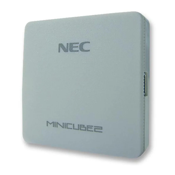
Page 16: Part Names And Functions Of Minicube2
CHAPTER NAMES AND FUNCTIONS OF HARDWARE Part Names and Functions of MINICUBE2 Figure 2-2 shows the part names of the MINICUBE2 main unit. For their functions, refer to (1) to (5) below. Figure 2-2. Part Names of MINICUBE2 USB interface USB interface Target interface Target interface... - Page 17 CHAPTER NAMES AND FUNCTIONS OF HARDWARE (3) USB interface connector This is a connector used to connect MINICUBE2 with the host machine, via a USB cable. A USB 2.0 compliant mini-B connector (UX60A-MB-5ST: Made by Hirose Electric Co., Ltd.) is employed. (4) Target interface connector This is a connector used to connect MINICUBE2 with the target system, via a 16-pin target cable.
-
Page 18: Part Names And Functions Of 78K0-Ocd Board
CHAPTER NAMES AND FUNCTIONS OF HARDWARE Part Names and Functions of 78K0-OCD Board The 78K0-OCD board is used for debugging a 78K0 microcontroller (not used for flash programming). Figure 2-3 illustrates the external view of the 78K0-OCD board. The name of each part is printed on the 78K0-OCD board. -
Page 19: Chapter 3 How To Use Minicube2 With V850 Microcontroller
CHAPTER HOW TO USE MINICUBE2 WITH V850 MICROCONTROLLER This chapter describes how to use MINICUBE2 when performing on-chip debugging and flash programming for a V850 microcontroller. On-chip debugging is a method to debug a microcontroller mounted on the target system, using a debug function implemented in the device. -
Page 20: Target System Design
The pins used for serial communication are basically the same as those of the flash memory programmer (such as PG-FP4), but some devices do not support some of them. Refer to the document ″QB-MINI2 Operating Precautions″ and check the supported pins. -
Page 21: Pin Assignment
CHAPTER HOW TO USE MINICUBE2 WITH V850 MICROCONTROLLER 3.1.1 Pin assignment This section describes the interface signals used between MINICUBE2 and the target system. Table 3-1 lists the pin assignment. Table 3-2 describes the functions of each pin. The pin assignment varies depending on whether CSI-H/S or UART is used, so design the circuit appropriately according to the circuit connection examples described on the following sections. -
Page 22: Circuit Connection Examples
CHAPTER HOW TO USE MINICUBE2 WITH V850 MICROCONTROLLER 3.1.2 Circuit connection examples The circuit design on the target system varies depending on the communication interface mode. Refer to the following table and see the relevant circuit connection example. Caution The constants described in the circuit connection example are reference values. If you perform flash programming aiming at mass production, thoroughly evaluate whether the specifications of the target device are satisfied. - Page 23 CHAPTER HOW TO USE MINICUBE2 WITH V850 MICROCONTROLLER <R> Figure 3-2. Recommended Circuit Connection When UART Is Used for Communication Interface Note 7 Target connector 3k to 10kΩ Target device RESET_OUT _RESET Note 1 Note 1 R.F.U. R.F.U. Clock R.F.U. circuit Note 2 Note 7...
- Page 24 CHAPTER HOW TO USE MINICUBE2 WITH V850 MICROCONTROLLER <R> Figure 3-3. Recommended Circuit Connection When CSI-H/S Is Used for Communication Interface Target device Target connector Note 7 Note 7 3k to 10kΩ 1k to 10kΩ RESET_OUT _RESET Note 1 Note 1 R.F.U.
-
Page 25: Connection Of Reset Pin
CHAPTER HOW TO USE MINICUBE2 WITH V850 MICROCONTROLLER 3.1.3 Connection of reset pin This section describes the connection of the reset pin, for which special attention must be paid, in circuit connection examples shown in the previous section. During on-chip debugging, a reset signal from the target system is input to MINICUBE2, masked, and then output to the target device. - Page 26 CHAPTER HOW TO USE MINICUBE2 WITH V850 MICROCONTROLLER (1) Automatically switching the reset signal via series resistor Figure 3-4 illustrates the reset pin connection described in 3.1.2 Circuit connection examples. This connection is designed assuming that the reset circuit on the target system contains an N-ch open-drain buffer (output resistance: 100Ω...
- Page 27 CHAPTER HOW TO USE MINICUBE2 WITH V850 MICROCONTROLLER (2) Manually switching the reset signal with jumper Figure 3-6 illustrates the circuit connection for the case where the reset signal is switched using the jumper, with or without MINICUBE2 connected. This connection is simple, but the jumper must be set manually. Figure 3-6.
-
Page 28: Mounting Connector Onto Target System
CHAPTER HOW TO USE MINICUBE2 WITH V850 MICROCONTROLLER 3.1.4 Mounting connector onto target system The connector must be mounted on the target system for connecting MINICUBE2 with the target system. A 2.54 mm pitch 16-pin general-purpose connector can be used. The following products are recommended. •... -
Page 29: On-Chip Debugging
CHAPTER HOW TO USE MINICUBE2 WITH V850 MICROCONTROLLER 3.2 On-Chip Debugging This section describes the system configuration, startup/shutdown procedure and cautions for debugging when on-chip debugging is performed with MINICUBE2. 3.2.1 Debug functions Table 3-4 lists the debug functions when a V850 microcontroller is the target device and the ID850QB is used. If a debugger other than the ID850QB (made by partner manufacturer) is used, the available functions may differ, so check the specifications of the debugger used. -
Page 30: System Configuration
CHAPTER HOW TO USE MINICUBE2 WITH V850 MICROCONTROLLER 3.2.2 System configuration Figure 3-9 illustrates the system configuration for on-chip debugging. Figure 3-9. System Configuration for On-Chip Debugging <5> <5> <3> <3> <4> <4> <1> <1> <6> <6> <2> <2> Target system Target system <1>... -
Page 31: System Startup Procedure
CHAPTER HOW TO USE MINICUBE2 WITH V850 MICROCONTROLLER 3.2.3 System startup procedure This section describes the system startup procedure. Observe the following order. (1) Preparation and installation of software The following software is required to perform on-chip debugging. For details on preparation and installation of software, refer to the setup manual supplied with MINICUBE2. - Page 32 ID. • Unsupported software (debugger, device file, or firmware) is used The software used may not support debugging of the target device. Refer to the document ″QB-MINI2 Operating Precautions″ and check the supported version.
-
Page 33: System Shutdown Procedure
CHAPTER HOW TO USE MINICUBE2 WITH V850 MICROCONTROLLER 3.2.4 System shutdown procedure Terminate debugging and shutdown the system in the following order. If the following order is not observed, the target system or MINICUBE2 may be damaged. (1) Debugger termination Terminate the debugger. -
Page 34: Securing Of User Resources And Setting Of Security Id
When a partner tool is used, read also the following material. When using MULTI manufactured by Green Hills Software QB-MINI2 Setup Manual User's Manual Partner Tool (U19158E) When using C-SPY manufactured by IAR Systems IAR C-SPY Hardware Debugger Systems User Guide issued by IAR Systems •... - Page 35 CHAPTER HOW TO USE MINICUBE2 WITH V850 MICROCONTROLLER (a) Reset vector A reset vector includes the jump instruction for the debug monitor program. [How to secure areas] It is not necessary to secure this area intentionally. When downloading a program, however, the debugger rewrites the reset vector in accordance with the following cases.
- Page 36 CHAPTER HOW TO USE MINICUBE2 WITH V850 MICROCONTROLLER (b) Securement of area for debug monitor program The shaded portions in Figure 3-12 are the areas where the debug monitor program is allocated. The monitor program performs initialization processing for debug communication interface and RUN or break processing for the CPU.
- Page 37 CHAPTER HOW TO USE MINICUBE2 WITH V850 MICROCONTROLLER (c) Securement of communication serial interface UART or CSI-H/S is used for communication between MINICUBE2 and the target system. The settings related to the serial interface modes are performed by the debug monitor program, but if the setting is changed by the user program, a communication error may occur.
- Page 38 CHAPTER HOW TO USE MINICUBE2 WITH V850 MICROCONTROLLER Example 2 Setting other than below is prohibited when the target device is the V850ES/HG2 and CSIB0 is used. PMC4 PMCCM PMCM Note Read-only x: Any Note The port values corresponding to the H/S pin are changed by the monitor program according to the debugger status.
- Page 39 CHAPTER HOW TO USE MINICUBE2 WITH V850 MICROCONTROLLER Address Value [7:0] 0x70 0x12 0x71 0x34 0x72 0x56 0x73 0x78 0x74 0x9A 0x75 0xBC 0x76 0xDE 0x77 0xF1 0x78 0x23 0x79 0xD4 If NEC Electronics compiler CA850 is used, the security ID can be set using the Compiler Common Options menu.
-
Page 40: Cautions On Debugging
CHAPTER HOW TO USE MINICUBE2 WITH V850 MICROCONTROLLER 3.2.6 Cautions on debugging This section describes cautions on performing on-chip debugging for a V850 microcontroller. Be sure to read the following to use MINICUBE2 properly. (1) Handling of device that was used for debugging Do not mount a device that was used for debugging on a mass-produced product, because the flash memory was rewritten during debugging and the number of rewrites of the flash memory cannot be guaranteed. - Page 41 CHAPTER HOW TO USE MINICUBE2 WITH V850 MICROCONTROLLER (6) Device with which the debugger startup is slowed When the debugger is started for the first time, chip erasure and writing of debug monitor program are performed. The following devices require about a dozen seconds for these operations. V850ES/JG2, V850ES/JJ2 V850ES/HE2, V850ES/HF2, V850ES/HG2, V850ES/HJ2 V850ES/IE2...
- Page 42 CHAPTER HOW TO USE MINICUBE2 WITH V850 MICROCONTROLLER • V850E/MA3 Note the following two points when debugging the V850E/MA3 as the target microcontroller. <1> If the “Multiply rate” is set to 1.25 or 2.5 in the Configuration dialog box when using the ID850QB, these values will be an integer 1 or 2 when the Configuration dialog box is opened the next time.
-
Page 43: Flash Programming
CHAPTER HOW TO USE MINICUBE2 WITH V850 MICROCONTROLLER 3.3 Flash Programming This section describes the system configuration and startup/shutdown procedure when flash programming is performed for a V850 microcontroller, using MINICUBE2. 3.3.1 Specifications of programming function Table 3-6. Specifications of Programming Function Functions Specifications USB 2.0 (compatible with 1.1) -
Page 44: System Startup Procedure
CHAPTER HOW TO USE MINICUBE2 WITH V850 MICROCONTROLLER 3.3.3 System startup procedure This section describes the system startup procedure. Observe the following order. (1) Preparation and installation of software The following software is required to perform flash programming. For details on preparation and installation of software, refer to the setup manual supplied with MINICUBE2. - Page 45 CHAPTER HOW TO USE MINICUBE2 WITH V850 MICROCONTROLLER (4) Connecting the USB cable Connect MINICUBE2 to the host machine as shown in Figure 3-16, before the power to the target system is turned on. When the power select switch is set to ″T″, the mode LED flashes white after connection. When the power select switch is set to ″3″...
-
Page 46: Usage Examples
CHAPTER HOW TO USE MINICUBE2 WITH V850 MICROCONTROLLER 3.3.4 Usage examples μ This section describes a series of basic operations using the QB-Programmer, using the PD70F3732 as an example. The operations from execution of the [Autoprocedure (EPV)] command to programming for the target device are described. - Page 47 CHAPTER HOW TO USE MINICUBE2 WITH V850 MICROCONTROLLER (1) Setting of programming environment Set the programming environment, following the steps <1> to <7> described below. <1> Click the [Device] menu on the menu bar and then click [Setup...]. <2> The Device Setup dialog box appears, in which the [Standard] tab is active. Figure 3-17.
- Page 48 CHAPTER HOW TO USE MINICUBE2 WITH V850 MICROCONTROLLER <4> Set the items in the [Target Device Connection], [Operation Mode] and [Supply Oscillator] areas, in accordance with your programming environment. The following figure shows an example. Figure 3-19. [Standard] Tab of Device Setup Dialog Box After Setting μ...
- Page 49 CHAPTER HOW TO USE MINICUBE2 WITH V850 MICROCONTROLLER <6> Next, set the items in the [Command options] and [Security flag settings] areas, in accordance with your programming environment. The following figure shows an example. Figure 3-21. [Advanced] Tab of Device Setup Dialog Box <7>...
- Page 50 CHAPTER HOW TO USE MINICUBE2 WITH V850 MICROCONTROLLER (2) Selection of program file Select the program file, following the steps <1> to <3> described below. <1> Click the [File] menu on the menu bar and then click [Load...]. <2> The program file select dialog box appears. Figure 3-23.
- Page 51 CHAPTER HOW TO USE MINICUBE2 WITH V850 MICROCONTROLLER (3) Execution of [Autoprocedure (EPV)] command Click the [Device] menu on the menu bar and then click [Autoprocedure (EPV)]. The [Blank Check], [Erase] (if the flash memory in the target device is not blank), [Program], [Verify] are executed for the target device sequentially.
-
Page 52: System Shutdown Procedure
CHAPTER HOW TO USE MINICUBE2 WITH V850 MICROCONTROLLER 3.3.5 System shutdown procedure Terminate flash programming and shutdown the system in the following order. If the following order is not observed, the target system or MINICUBE2 may be damaged. (1) Terminating the QB-Programmer Terminate the QB-Programmer if you are not going to perform programming to other devices. -
Page 53: Chapter 4 How To Use Minicube2 With 78K0 Microcontroller
CHAPTER HOW TO USE MINICUBE2 WITH 78K0 MICROCONTROLLER This chapter describes how to use MINICUBE2 when performing on-chip debugging and flash programming for a 78K0 microcontroller. On-chip debugging is a method to debug a microcontroller mounted on the target system, using a debug function implemented in the device. -
Page 54: Target System Design
CHAPTER HOW TO USE MINICUBE2 WITH 78K0 MICROCONTROLLER <R> 4.1 Target System Design This section describes the target system circuit design required for on-chip debugging and flash programming. Because the communication mode for on-chip debugging differs depending on the target device, the target system configuration varies. - Page 55 CHAPTER HOW TO USE MINICUBE2 WITH 78K0 MICROCONTROLLER Figure 4-1 and Figure 4-2 present overviews of the MINICUBE2 communication interface. For communication between MINICUBE2 and the target system, communication circuits must be mounted on the target system, as shown on the left side of the figure. Refer to this section to design circuits appropriately.
-
Page 56: Pin Assignment
CHAPTER HOW TO USE MINICUBE2 WITH 78K0 MICROCONTROLLER 4.1.1 Pin assignment This section describes the interface signals used between MINICUBE2 and the target system. Table 4-1 lists the pin assignment when a 16-pin target cable is used. Table 4-2 describes the functions of each pin. The pin assignment varies depending on whether the operation is debugging or programming, so design the circuit appropriately according to the circuit connection examples described on the following sections. - Page 57 CHAPTER HOW TO USE MINICUBE2 WITH 78K0 MICROCONTROLLER Table 4-3 lists the pin assignment when a 10-pin target cable is used. The 10-pin target cable uses the OCDxA and OCDxB pins and is dedicated to debugging. Use this cable if the target system is designed for MINICUBE (QB-78K0MINI) or in order to limit the usage of the connector mounted on the target system only for debugging.
-
Page 58: Circuit Connection Examples
CHAPTER HOW TO USE MINICUBE2 WITH 78K0 MICROCONTROLLER 4.1.2 Circuit connection examples The circuit design on the target system varies depending on the used connector and interface signals. The following (1) to (3) are the major purpose of use. Confirm the purpose, refer to Table 4-5 and see the relevant circuit connection example for specifications. - Page 59 CHAPTER HOW TO USE MINICUBE2 WITH 78K0 MICROCONTROLLER <R> Figure 4-3. Flow Chart for Selecting the Circuit Which pins do you OCDxA/B, UART TOOLDx want to use to communicate with MINICUBE2? Which pins do you TOOLD1 TOOLD0 want to use to communicate with What do you want to MINICUBE2?
- Page 60 CHAPTER HOW TO USE MINICUBE2 WITH 78K0 MICROCONTROLLER <R> Figure 4-4. When Both Debugging and Programming Are Performed (Not communicating by using the OCD0A and OCD0B pins or not using the X1 oscillator) Target connector Target device Note 7 3 k to kΩ RESET_OUT RESET Note 1...
- Page 61 CHAPTER HOW TO USE MINICUBE2 WITH 78K0 MICROCONTROLLER Figure 4-5. When Both Debugging and Programming Are Performed <R> (Communicating by using the OCD0A and OCD0B pins or using the X1 oscillator) Target connector Target device Note 7 3 k to 10 kΩ RESET_OUT RESET Note 1...
- Page 62 CHAPTER HOW TO USE MINICUBE2 WITH 78K0 MICROCONTROLLER Figure 4-6. When Both Debugging and Programming Are Performed <R> (Not communicating by using the OCD1A and OCD1B pins or using the X1 oscillator) Target connector Target device Note 6 3 k to 10 kΩ RESET RESET_OUT Note 1...
- Page 63 CHAPTER HOW TO USE MINICUBE2 WITH 78K0 MICROCONTROLLER Figure 4-7. When Both Debugging and Programming Are Performed <R> (Communicating by using the OCD1A and OCD1B pins or using the X1 oscillator) Target connector Target device Note 5 3 k to 10 kΩ RESET_OUT RESET Note 1...
- Page 64 CHAPTER HOW TO USE MINICUBE2 WITH 78K0 MICROCONTROLLER Figure 4-8. When Both Debugging and Programming Are Performed <R> (with X1/X2 oscillator is not used , with TOOLC0/TOOLD0 communication) Target connector Target device 3 k to 10 kΩ Note 1 RESET RESET_OUT Note 3 TOOLD0(X2)
- Page 65 CHAPTER HOW TO USE MINICUBE2 WITH 78K0 MICROCONTROLLER Figure 4-9. When Both Debugging and Programming Are Performed <R> (with X1/X2 oscillator is used, with TOOLC0/TOOLD0 communication) Target connector Target device Note 1 RESET RESET_OUT Note 3 TOOLD0(X2) Note 5 R.F.U. R.F.U.
- Page 66 CHAPTER HOW TO USE MINICUBE2 WITH 78K0 MICROCONTROLLER Figure 4-10. When Both Debugging and Programming Are Performed <R> (with TOOLC0/TOOLD0 communication) Target connector Target device 3 k to 10 kΩ Note 1 RESET_OUT RESET Note 3 TOOLD1 R.F.U. R.F.U. R.F.U. Note 2 Note 3 TOOLC1...
- Page 67 CHAPTER HOW TO USE MINICUBE2 WITH 78K0 MICROCONTROLLER Figure 4-11. When Only Debugging Is Performed (with OCD0A/OCD0B communication) <R> 1kΩ Reset connector RESET signal Target connector Target device 10kΩ Note 1 RESET_IN RESET_OUT _RESET FLMD0 FLMD0 Note 2 OCD0B(X2) DATA Note 3 OCD0A(X1) 1kΩ...
- Page 68 CHAPTER HOW TO USE MINICUBE2 WITH 78K0 MICROCONTROLLER Figure 4-12. When Only Debugging Is Performed (with OCD1A/OCD1B communication) <R> 1kΩ 3k to Reset connector Note 5 10kΩ RESET signal Target connector 10kΩ Target device Note 1 RESET_IN RESET_OUT _RESET FLMD0 FLMD0 Note 2 DATA...
- Page 69 CHAPTER HOW TO USE MINICUBE2 WITH 78K0 MICROCONTROLLER Figure 4-13. When Only Programming Is Performed Note 5 3k to 10kΩ Target device Target connector Note 1 RESET_OUT _RESET Note 2 Note 2 R.F.U. Note 5 1k to 10kΩ R.F.U. R.F.U. Note 3 R.F.U.
-
Page 70: Connection Of Reset Pin
CHAPTER HOW TO USE MINICUBE2 WITH 78K0 MICROCONTROLLER 4.1.3 Connection of reset pin This section describes the connection of the reset pin, for which special attention must be paid, in circuit connection examples shown in the previous section. During on-chip debugging, a reset signal from the target system is input to MINICUBE2, masked, and then output to the target device. - Page 71 CHAPTER HOW TO USE MINICUBE2 WITH 78K0 MICROCONTROLLER (1) Automatically switching the reset signal via resistor Figure 4-15 illustrates the reset pin connection described in 4.1.2 Circuit connection examples. This connection is designed assuming that the reset circuit on the target system contains an N-ch open-drain buffer (output resistance: 100Ω...
- Page 72 CHAPTER HOW TO USE MINICUBE2 WITH 78K0 MICROCONTROLLER (2) Automatically switching the reset signal via selector logic (Only for devices that have no FLMDPUP <R> register but have a FLMD0 pin) Figure 4-17 illustrates the circuit connection for the case where the reset signal is switched automatically using the selector logic, with or without MINICUBE2 connected.
- Page 73 CHAPTER HOW TO USE MINICUBE2 WITH 78K0 MICROCONTROLLER (3) Manually switching the reset signal with jumper Figure 4-19 illustrates the circuit connection for the case where the reset signal is switched using the jumper, with or without MINICUBE2 connected. This connection is simple, but the jumper must be set manually. Figure 4-19.
- Page 74 CHAPTER HOW TO USE MINICUBE2 WITH 78K0 MICROCONTROLLER (4) Resetting the target device by power-on clear (POC) only Figure 4-21 illustrates the circuit connection for the case where the target device is only reset via POC without using the reset pin. RESET_OUT becomes active when power is applied to MINICUBE2. Even if power supply to the target system is turned off during debugging, pseudo POC function emulation is <R>...
-
Page 75: Cautions On Target System Design
CHAPTER HOW TO USE MINICUBE2 WITH 78K0 MICROCONTROLLER 4.1.4 Cautions on target system design Note the following cautions when designing the target system. <R> • If possible, do not create sections in which the communication lines for debugging (OCDxA, OCDxB, TOOLCx, and TOOLDx) run in parallel in the target system. -
Page 76: Mounting Connector Onto Target System
CHAPTER HOW TO USE MINICUBE2 WITH 78K0 MICROCONTROLLER 4.1.5 Mounting connector onto target system The connector must be mounted on the target system for connecting MINICUBE2 with the target system. 2.54 mm pitch 10- or 16-pin general-purpose connector can be used. The following products are recommended. -
Page 77: On-Chip Debugging
Internal ROM: 256 to 400 bytes Internal RAM: 7 to 9 bytes Differs depending on the device. For details, refer to the document ″QB-MINI2 Operating Precautions″. <R> Function pins used for debugging The pin shared with OCDxA and OCDxB, the pin shared with TOOLCx and ¯¯¯¯¯¯¯¯¯¯... -
Page 78: System Configuration
CHAPTER HOW TO USE MINICUBE2 WITH 78K0 MICROCONTROLLER 4.2.2 System configuration Figure 4-24 illustrates the system configuration for on-chip debugging. Figure 4-24. System Configuration for On-Chip Debugging <6> <6> <3> <3> <5> <5> <4> <4> <1> <1> <7> <7> <8> <8>... -
Page 79: System Startup Procedure
CHAPTER HOW TO USE MINICUBE2 WITH 78K0 MICROCONTROLLER 4.2.3 System startup procedure This section describes the system startup procedure. Observe the following order. (1) Preparation and installation of software The following software is required to perform on-chip debugging. For details on preparation and installation of software, refer to the setup manual supplied with MINICUBE2. - Page 80 CHAPTER HOW TO USE MINICUBE2 WITH 78K0 MICROCONTROLLER (4) Connecting the target system Connect MINICUBE2 to the target system as shown in Figure 4-25. Select a 10- or 16-pin target cable according to the target system circuit (refer to Remark below). Perform connection before the power to the target system is turned on Figure 4-25.
- Page 81 Securing of user resources and setting of security ID. • Unsupported software (debugger, device file, or firmware) is used Refer to the document ″QB-MINI2 The software used may not support debugging of the target device. Operating Precautions″ and check the supported version.
-
Page 82: System Shutdown Procedure
CHAPTER HOW TO USE MINICUBE2 WITH 78K0 MICROCONTROLLER 4.2.4 System shutdown procedure Terminate debugging and shutdown the system in the following order. If the following order is not observed, the target system or MINICUBE2 may be damaged. (1) Debugger termination Terminate the debugger. -
Page 83: Clock Setting
CHAPTER HOW TO USE MINICUBE2 WITH 78K0 MICROCONTROLLER 4.2.5 Clock setting <R> The clock signal generated by the X1 oscillator, internal high-speed oscillator, or subsystem clock oscillator can be used for the clock signal of the target device during on-chip debugging. Setting up each is described below. - Page 84 CHAPTER HOW TO USE MINICUBE2 WITH 78K0 MICROCONTROLLER (c) Using the oscillator connected to the 78K0-OCD board (only when OCD0A and OCD0B or TOOLD0 and TOOLC0 are used) Connect an oscillator or oscillation circuit to CLK1 on the 78K0-OCD board. (“Clock Board”...
- Page 85 CHAPTER HOW TO USE MINICUBE2 WITH 78K0 MICROCONTROLLER (d) Using the oscillator circuit connected to the 78K0-OCD board (only when OCD0A and OCD0B or TOOLD0 and TOOLC0 are used) Connect an oscillator or oscillation circuit to CLK1 on the 78K0-OCD board. (“Clock Board”...
- Page 86 CHAPTER HOW TO USE MINICUBE2 WITH 78K0 MICROCONTROLLER (2) Using the internal high-speed clock (when no restrictions are applied by the occupied pins) MINICUBE2 operates on the internal high-speed oscillator of the target device, regardless of the setting specified for “Main Clock” in the Configuration dialog box of the debugger. However, the clock specified by the debugger is used for downloading a program when the debugger starts.
-
Page 87: Securing Of User Resources And Setting Of Security Id
CHAPTER HOW TO USE MINICUBE2 WITH 78K0 MICROCONTROLLER 4.2.6 Securing of user resources and setting of security ID MINICUBE2 uses the user memory spaces (shaded portions in Figure 4-32) to implement communication with the target device, or each debug functions. The areas marked with a dot (•) are always used for debugging, and other areas are used for each debug function used. - Page 88 CHAPTER HOW TO USE MINICUBE2 WITH 78K0 MICROCONTROLLER (a) Debug monitor area (this area must be secured) Addresses 0x02, 0x03 and area starting from address 0x8F must be secured to embed the debug monitor program. If this area is rewritten by flash self programming, on-chip debugging can no longer be performed. [How to secure areas] When using NEC Electronics compiler CC78K0, addresses 0x02, 0x03 and area starting from address can be secured for debug monitoring, using the linker option (-go).
- Page 89 CHAPTER HOW TO USE MINICUBE2 WITH 78K0 MICROCONTROLLER (b) Option byte area (essential) This is the area for the security setting to prevent the flash memory from being read by an unauthorized person. The target device operates in accordance with the set value, as shown below. Table 4-8.
- Page 90 CHAPTER HOW TO USE MINICUBE2 WITH 78K0 MICROCONTROLLER (c) Security ID area (essential) This is the area for the security setting to prevent the flash memory from being read by an unauthorized person. The security ID functions as a password for starting the debugger. The debugger starts only when the security ID that is input during debugger startup and the security ID embedded in this area match.
- Page 91 CHAPTER HOW TO USE MINICUBE2 WITH 78K0 MICROCONTROLLER (d) Stack area for debugging (this area must be secured) This area requires 7 to 9 bytes as the stack area for debugging. Since this area is allocated immediately before the stack area, the address of this area varies depending on the stack increase and decrease. Figure 4-35 illustrates the case where the stack area is increased when the internal high-speed RAM starts from 0xFB00.
- Page 92 Add 256 bytes to the area specified in (a) (to make the area 512 bytes in total). For details about the RAM monitoring area, refer to the document ″QB-MINI2 Operating Precautions″. Figure 4-36. Linker Option Setting (When Pseudo RAM Monitor and Software Break Are Used) User’s Manual...
-
Page 93: Cautions On Debugging
CHAPTER HOW TO USE MINICUBE2 WITH 78K0 MICROCONTROLLER 4.2.7 Cautions on debugging This section describes cautions on performing on-chip debugging for a 78K0 microcontroller. Be sure to read the following to use MINICUBE2 properly. (1) Handling of device that was used for debugging Do not mount a device that was used for debugging on a mass-produced product, because the flash memory was rewritten during debugging and the number of rewrites of the flash memory cannot be guaranteed. - Page 94 CHAPTER HOW TO USE MINICUBE2 WITH 78K0 MICROCONTROLLER (5) Emulation in self programming mode For self programming, the mode is switched from normal mode to self programming mode. MOV PFCMD,#0A5H ← (1) MOV FLPMC,#1H MOV FLPMC,#0FEH MOV FLPMC,#1H ----------------------- From this position ←...
- Page 95 CHAPTER HOW TO USE MINICUBE2 WITH 78K0 MICROCONTROLLER (8) Software break (2) If the debugger does not terminate normally due to a factor such as a freeze while a software break is set, the instruction for which the software break is set and that has been substituted by a debug instruction remains as is.
- Page 96 CHAPTER HOW TO USE MINICUBE2 WITH 78K0 MICROCONTROLLER (11)Caution on mounting a clock on 78K0-OCD board When a clock is mounted on the 78K0-OCD board, power supply may not become the GND level even if the power to the target system is shut down. (12) Emulation of POC function If power supply to the target system is turned off during debugging, the target device enters the reset state by the RESET_OUT pin of MINICUBE2.
-
Page 97: Flash Programming
CHAPTER HOW TO USE MINICUBE2 WITH 78K0 MICROCONTROLLER 4.3 Flash Programming This section describes the system configuration and startup/shutdown procedure when flash programming is performed for a 78K0 microcontroller, using MINICUBE2. 4.3.1 Specifications of programming function Table 4-11. Specifications of Programming Function Functions Specifications USB 2.0 (compatible with 1.1) -
Page 98: System Startup Procedure
CHAPTER HOW TO USE MINICUBE2 WITH 78K0 MICROCONTROLLER 4.3.3 System startup procedure This section describes the system startup procedure. Observe the following order. (1) Preparation and installation of software The following software is required to perform flash programming. For details on preparation and installation of software, refer to the setup manual supplied with MINICUBE2. - Page 99 CHAPTER HOW TO USE MINICUBE2 WITH 78K0 MICROCONTROLLER (4) Connecting the USB cable Connect MINICUBE2 to the host machine as shown in Figure 4-39, before the power to the target system is turned on. When the power select switch is set to ″T″, the mode LED flashes white after connection. When the power select switch is set to ″3″...
-
Page 100: Usage Examples
CHAPTER HOW TO USE MINICUBE2 WITH 78K0 MICROCONTROLLER 4.3.4 Usage examples μ This section describes a series of basic operations using the QB-Programmer, using the PD78F0547D as an example. The operations from execution of the [Autoprocedure (EPV)] command to programming for the target device are described. - Page 101 CHAPTER HOW TO USE MINICUBE2 WITH 78K0 MICROCONTROLLER (1) Setting of programming environment Set the programming environment, following the steps <1> to <6> described below. <1> Click the [Device] menu on the menu bar and then click [Setup...]. <2> The Device Setup dialog box appears, in which the [Standard] tab is active. Figure 4-40.
- Page 102 CHAPTER HOW TO USE MINICUBE2 WITH 78K0 MICROCONTROLLER <4> Set the items in the [Target Device Connection], [Operation Mode] and [Supply Oscillator] areas, in accordance with your programming environment. The following figure shows an example. Figure 4-42. [Standard] Tab of Device Setup Dialog Box After Setting <5>...
- Page 103 CHAPTER HOW TO USE MINICUBE2 WITH 78K0 MICROCONTROLLER <6> By clicking the OK button, the programming environment is set and the Device Setup dialog box is closed. The main window appears as follows. Figure 4-44. Completion of Programming Environment Setting User’s Manual U18371EJ5V0UM...
- Page 104 CHAPTER HOW TO USE MINICUBE2 WITH 78K0 MICROCONTROLLER (2) Selection of program file Select the program file, following the steps <1> to <3> described below. <1> Click the [File] menu on the menu bar and then click [Load...]. <2> The program file select dialog box appears. Figure 4-45.
- Page 105 CHAPTER HOW TO USE MINICUBE2 WITH 78K0 MICROCONTROLLER (3) Execution of [Autoprocedure (EPV)] command Click the [Device] menu on the menu bar and then click [Autoprocedure (EPV)]. <R> The [Blank Check], [Erase] (if the flash memory in the target device is not blank), [Program], [Verify] are executed for the target device sequentially.
-
Page 106: System Shutdown Procedure
CHAPTER HOW TO USE MINICUBE2 WITH 78K0 MICROCONTROLLER 4.3.5 System shutdown procedure Terminate flash programming and shutdown the system in the following order. If the following order is not observed, the target system or MINICUBE2 may be damaged. (1) Terminating the QB-Programmer Terminate the QB-Programmer if you are not going to perform programming to other devices. -
Page 107: Chapter 5 How To Use Minicube2 With 78K0S Microcontroller
CHAPTER HOW TO USE MINICUBE2 WITH 78K0S MICROCONTROLLER This chapter describes how to use MINICUBE2 when performing on-chip debugging and flash programming for a 78K0S microcontroller. To perform on-chip debugging for a 78K0S microcontroller, a specific program (debug function) must be downloaded to the device, and then debug the device mounted on the target system. -
Page 108: Target System Design
CHAPTER HOW TO USE MINICUBE2 WITH 78K0S MICROCONTROLLER 5.1 Target System Design This section describes the target system circuit design required for on-chip debugging and flash programming. Figure 5-1 presents an overview of the MINICUBE2 communication interface. As shown on the left side of the figure, MINICUBE2 performs serial communication with the target device on the target system. -
Page 109: Pin Assignment
CHAPTER HOW TO USE MINICUBE2 WITH 78K0S MICROCONTROLLER 5.1.1 Pin assignment This section describes the interface signals used between MINICUBE2 and the target system. Table 5-1 lists the pin assignment. Table 5-2 describes the functions of each pin. The pin assignment varies depending on whether the operation is debugging or programming, so design the circuit appropriately according to the circuit connection examples described on the following sections. -
Page 110: Circuit Connection Example
CHAPTER HOW TO USE MINICUBE2 WITH 78K0S MICROCONTROLLER 5.1.2 Circuit connection example Refer to Figure 5-2 and design an appropriate circuit. Caution The constants described in the circuit connection example are reference values. If you perform flash programming aiming at mass production, thoroughly evaluate whether the specifications of the target device are satisfied. -
Page 111: Connection Of Reset Pin
CHAPTER HOW TO USE MINICUBE2 WITH 78K0S MICROCONTROLLER 5.1.3 Connection of reset pin This section describes the connection of the reset pin, for which special attention must be paid, in the circuit connection example shown in the previous section. During on-chip debugging, a reset signal from the target system is input to MINICUBE2, masked, and then output to the target device. - Page 112 CHAPTER HOW TO USE MINICUBE2 WITH 78K0S MICROCONTROLLER (1) Automatically switching the reset signal via series resistor Figure 5-3 illustrates the reset pin connection described in 5.1.2 Circuit connection example. This connection is designed assuming that the reset circuit on the target system contains an N-ch open-drain buffer (output resistance: 100Ω...
- Page 113 CHAPTER HOW TO USE MINICUBE2 WITH 78K0S MICROCONTROLLER (2) Manually switching the reset signal with jumper Figure 5-5 illustrates the circuit connection for the case where the reset signal is switched using the jumper, with or without MINICUBE2 connected. This connection is simple, but the jumper must be set manually. Figure 5-5.
-
Page 114: Connection Of Intp Pin
CHAPTER HOW TO USE MINICUBE2 WITH 78K0S MICROCONTROLLER 5.1.4 Connection of INTP pin The INTP pin is used only for communication between MINICUBE2 and the target device during debugging. Design circuits appropriately according to the relevant case among the cases shown below. (1) INTP pin is not used in target system (as is illustrated in Figure 5-2. - Page 115 CHAPTER HOW TO USE MINICUBE2 WITH 78K0S MICROCONTROLLER Figure 5-9. Circuit Connection for the Case Where MINICUBE2 Is Used for Debugging and Debugging of INTP Pin Is Performed Only with Real Machine 1 kΩ 1 kΩ Target connector Target connector Target device Target device Jumper...
-
Page 116: Connection Of X1 And X2 Pins
CHAPTER HOW TO USE MINICUBE2 WITH 78K0S MICROCONTROLLER 5.1.5 Connection of X1 and X2 pins The X1 and X2 pins are used when the debugger is started for the first time (when downloading the monitor program) and when programming is performed with the QB-Programmer. Design circuits appropriately according to the relevant case among the cases shown below. -
Page 117: Mounting Connector Onto Target System
CHAPTER HOW TO USE MINICUBE2 WITH 78K0S MICROCONTROLLER 5.1.6 Mounting connector onto target system The connector must be mounted on the target system for connecting MINICUBE2 with the target system. 2.54 mm pitch 16-pin general-purpose connector can be used. The following products are recommended. •... -
Page 118: On-Chip Debugging
, X2 , RESET Note The INTP pins to be used are described in the document ″QB-MINI2 Operating Precautions″. The X1 and X2 pins are used only when the debugger is started for the first time (when downloading the monitor program). -
Page 119: System Configuration
CHAPTER HOW TO USE MINICUBE2 WITH 78K0S MICROCONTROLLER 5.2.2 System configuration Figure 5-13 illustrates the system configuration for on-chip debugging. Figure 5-13. System Configuration for On-Chip Debugging <5> <5> <3> <3> <4> <4> <1> <1> <6> <6> <2> <2> Target system Target system <1>... -
Page 120: System Startup Procedure
CHAPTER HOW TO USE MINICUBE2 WITH 78K0S MICROCONTROLLER 5.2.3 System startup procedure This section describes the system startup procedure. Observe the following order. (1) Preparation and installation of software The following software is required to perform on-chip debugging. For details on preparation and installation of software, refer to the setup manual supplied with MINICUBE2. - Page 121 5.2.5 Securing of user resources. • Unsupported software (debugger, device file, or firmware) is used Refer to the document ″QB-MINI2 The software used may not support debugging of the target device. Operating Precautions″ and check the supported version. When using software provided by an NEC Electronics partner, refer to the documents prepared by the partner company.
-
Page 122: System Shutdown Procedure
CHAPTER HOW TO USE MINICUBE2 WITH 78K0S MICROCONTROLLER 5.2.4 System shutdown procedure Terminate debugging and shutdown the system in the following order. If the following order is not observed, the target system or MINICUBE2 may be damaged. (1) Debugger termination Terminate the debugger. -
Page 123: Securing Of User Resources
CHAPTER HOW TO USE MINICUBE2 WITH 78K0S MICROCONTROLLER 5.2.5 Securing of user resources The user must prepare the following to perform communication between MINICUBE2 and the target device and implement each debug function. Refer to the descriptions on the following pages and set these items in the user program or using the compiler options. - Page 124 CHAPTER HOW TO USE MINICUBE2 WITH 78K0S MICROCONTROLLER (1) Securement of area for debug monitor program In the internal ROM space of the target device, the shaded portions in Figure 5-16 are the areas where the debug monitor program is allocated. The monitor program performs initialization processing for debug communication interface and RUN or break processing for the CPU.
- Page 125 CHAPTER HOW TO USE MINICUBE2 WITH 78K0S MICROCONTROLLER Describe the address to the portion of ″0ed0h″ in accordance with the flash memory capacity of the Remark target device (see the following table). Flash Memory Capacity of Value Described in Target Device Assembler Source 1 KB 0x2D0...
- Page 126 CHAPTER HOW TO USE MINICUBE2 WITH 78K0S MICROCONTROLLER (3) Securement of communication serial interface The INTP pin is used for communication between MINICUBE2 and the target system. The settings related to the INTP pin are performed by the debug monitor program, but if the setting is changed by the user program, a communication error may occur.
-
Page 127: Debugging Of Alternate-Functions Of X1 And X2 Pins
CHAPTER HOW TO USE MINICUBE2 WITH 78K0S MICROCONTROLLER 5.2.6 Debugging of alternate-functions of X1 and X2 pins The X1 and X2 pins are used when the debugger is started for the first time (when downloading the monitor program) and when programming is performed with the QB-Programmer. It is not necessary to use the X1 and X2 pins if the monitor program has already been downloaded to the target device, so the X1 and X2 pins and their alternate functions can be debugged by using the following procedures. -
Page 128: Cautions On Debugging
CHAPTER HOW TO USE MINICUBE2 WITH 78K0S MICROCONTROLLER 5.2.7 Cautions on debugging This section describes cautions on performing on-chip debugging for a 78K0S microcontroller. Be sure to read the following to use MINICUBE2 properly. (1) Handling of device that was used for debugging Do not mount a device that was used for debugging on a mass-produced product, because the flash memory was rewritten during debugging and the number of rewrites of the flash memory cannot be guaranteed. - Page 129 CHAPTER HOW TO USE MINICUBE2 WITH 78K0S MICROCONTROLLER (7) Emulation of POC function The POC function of the target device cannot be emulated. Make sure that the power to the target system is not shut down during debugging. (8) Debugging with real machine running without using MINICUBE2 If debugging is performed with a real machine running, without using MINICUBE2, write the user program using the QB-Programmer.
-
Page 130: Flash Programming
CHAPTER HOW TO USE MINICUBE2 WITH 78K0S MICROCONTROLLER 5.3 Flash Programming This section describes the system configuration and startup/shutdown procedure when flash programming is performed for a 78K0S microcontroller, using MINICUBE2. 5.3.1 Specifications of programming function Table 5-5. Specifications of Programming Function Functions Specifications Host interface... -
Page 131: System Startup Procedure
CHAPTER HOW TO USE MINICUBE2 WITH 78K0S MICROCONTROLLER 5.3.3 System startup procedure This section describes the system startup procedure. Observe the following order. (1) Preparation and installation of software The following software is required to perform flash programming. For details on preparation and installation of software, refer to the setup manual supplied with MINICUBE2. - Page 132 CHAPTER HOW TO USE MINICUBE2 WITH 78K0S MICROCONTROLLER (4) Connecting the USB cable Connect MINICUBE2 to the host machine as shown in Figure 5-19, before the power to the target system is turned on. When the power select switch is set to ″T″, the mode LED flashes white after connection. When the power select switch is set to ″3″...
-
Page 133: Usage Examples
CHAPTER HOW TO USE MINICUBE2 WITH 78K0S MICROCONTROLLER 5.3.4 Usage examples μ This section describes a series of basic operations using the QB-Programmer, using the PD78F9234 as an example. The operations from execution of the [Autoprocedure (EPV)] command to programming for the target device are described. - Page 134 CHAPTER HOW TO USE MINICUBE2 WITH 78K0S MICROCONTROLLER (1) Setting of programming environment Set the programming environment, following the steps <1> to <6> described below. <1> Click the [Device] menu on the menu bar and then click [Setup...]. <2> The Device Setup dialog box appears, in which the [Standard] tab is active. Figure 5-20.
- Page 135 CHAPTER HOW TO USE MINICUBE2 WITH 78K0S MICROCONTROLLER <4> Set the items in the [Target Device Connection], [Operation Mode] and [Supply Oscillator] areas, in accordance with your programming environment. The following figure shows an example. Figure 5-22. [Standard] Tab of Device Setup Dialog Box After Setting <5>...
- Page 136 CHAPTER HOW TO USE MINICUBE2 WITH 78K0S MICROCONTROLLER <6> By clicking the OK button, the programming environment is set and the Device Setup dialog box is closed. The main window appears as follows. Figure 5-24. Completion of Programming Environment Setting User’s Manual U18371EJ5V0UM...
- Page 137 CHAPTER HOW TO USE MINICUBE2 WITH 78K0S MICROCONTROLLER (2) Selection of program file Select the program file, following the steps <1> to <3> described below. <1> Click the [File] menu on the menu bar and then click [Load...]. <2> The program file select dialog box appears. Figure 5-25.
- Page 138 CHAPTER HOW TO USE MINICUBE2 WITH 78K0S MICROCONTROLLER (3) Execution of [Autoprocedure (EPV)] command Click the [Device] menu on the menu bar and then click [Autoprocedure (EPV)]. The [Blank Check], [Erase] (if the flash memory in the target device is not blank), [Program], [Checksum] <R>...
-
Page 139: System Shutdown Procedure
CHAPTER HOW TO USE MINICUBE2 WITH 78K0S MICROCONTROLLER 5.3.5 System shutdown procedure Terminate flash programming and shutdown the system in the following order. If the following order is not observed, the target system or MINICUBE2 may be damaged. (1) Terminating the QB-Programmer Terminate the QB-Programmer if you are not going to perform programming to other devices. -
Page 140: Chapter 6 How To Use Minicube2 With 78K0R Microcontroller
CHAPTER HOW TO USE MINICUBE2 WITH 78K0R MICROCONTROLLER This chapter describes how to use MINICUBE2 when performing on-chip debugging and flash programming for a 78K0R microcontroller. On-chip debugging is a method to debug a microcontroller mounted on the target system, using a debug function implemented in the device. -
Page 141: Target System Design
CHAPTER HOW TO USE MINICUBE2 WITH 78K0R MICROCONTROLLER 6.1 Target System Design This section describes the target system circuit design required for on-chip debugging and flash programming. Figure 6-1 presents an overview of the MINICUBE2 communication interface. As shown on the left side of the figure, MINICUBE2 performs serial communication with the target device on the target system. -
Page 142: Pin Assignment
CHAPTER HOW TO USE MINICUBE2 WITH 78K0R MICROCONTROLLER 6.1.1 Pin assignment This section describes the interface signals used between MINICUBE2 and the target system. Table 6-2 lists the pin assignment. Table 6-3 describes the functions of each pin. The pin assignment varies between 1-wire and 2-wire modes, so design the circuit appropriately according to the circuit connection examples described on the following sections. -
Page 143: Circuit Connection Example
CHAPTER HOW TO USE MINICUBE2 WITH 78K0R MICROCONTROLLER 6.1.2 Circuit connection example Refer to Figure 6-2 and design an appropriate circuit. Caution The constants described in the circuit connection example are reference values. If you perform flash programming aiming at mass production, thoroughly evaluate whether the specifications of the target device are satisfied. -
Page 144: Connection Of Reset Pin
CHAPTER HOW TO USE MINICUBE2 WITH 78K0R MICROCONTROLLER 6.1.3 Connection of reset pin This section describes the connection of the reset pin, for which special attention must be paid, in the circuit connection example shown in the previous section. During on-chip debugging, a reset signal from the target system is input to MINICUBE2, masked, and then output to the target device. - Page 145 CHAPTER HOW TO USE MINICUBE2 WITH 78K0R MICROCONTROLLER (1) Automatically switching the reset signal via series resistor Figure 6-3 illustrates the reset pin connection described in 6.1.2 Circuit connection example. This connection is designed assuming that the reset circuit on the target system contains an N-ch open-drain buffer (output resistance: 100Ω...
- Page 146 CHAPTER HOW TO USE MINICUBE2 WITH 78K0R MICROCONTROLLER (2) Manually switching the reset signal with jumper Figure 6-5 illustrates the circuit connection for the case where the reset signal is switched using the jumper, with or without MINICUBE2 connected. This connection is simple, but the jumper must be set manually. Figure 6-5.
-
Page 147: Mounting Connector Onto Target System
CHAPTER HOW TO USE MINICUBE2 WITH 78K0R MICROCONTROLLER 6.1.4 Mounting connector onto target system The connector must be mounted on the target system for connecting MINICUBE2 with the target system. A 2.54 mm pitch 16-pin general-purpose connector can be used. The following products are recommended. •... -
Page 148: On-Chip Debugging
CHAPTER HOW TO USE MINICUBE2 WITH 78K0R MICROCONTROLLER 6.2 On-Chip Debugging This section describes the system configuration, startup/shutdown procedure and cautions for debugging when on-chip debugging is performed with MINICUBE2. 6.2.1 Debug functions Table 6-4 lists the debug functions when a 78K0R microcontroller is the target device and the ID78K0R-QB is used. -
Page 149: System Configuration
CHAPTER HOW TO USE MINICUBE2 WITH 78K0R MICROCONTROLLER 6.2.2 System configuration Figure 6-8 illustrates the system configuration for on-chip debugging. Figure 6-8. System Configuration for On-Chip Debugging <5> <5> <3> <3> <4> <4> <1> <1> <6> <6> <2> <2> Target system Target system <1>... -
Page 150: System Startup Procedure
CHAPTER HOW TO USE MINICUBE2 WITH 78K0R MICROCONTROLLER 6.2.3 System startup procedure This section describes the system startup procedure. Observe the following order. (1) Preparation and installation of software The following software is required to perform on-chip debugging. For details on preparation and installation of software, refer to the setup manual supplied with MINICUBE2. - Page 151 ID and on-chip debug option byte. • Unsupported software (debugger, device file, or firmware) is used The software used may not support debugging of the target device. Refer to the document ″QB-MINI2 Operating Precautions″ and check the supported version.
-
Page 152: System Shutdown Procedure
CHAPTER HOW TO USE MINICUBE2 WITH 78K0R MICROCONTROLLER 6.2.4 System shutdown procedure Terminate debugging and shutdown the system in the following order. If the following order is not observed, the target system or MINICUBE2 may be damaged. (1) Debugger termination Terminate the debugger. -
Page 153: Securing Of User Resources And Setting Of Security Id And On-Chip Debug Option Byte
CHAPTER HOW TO USE MINICUBE2 WITH 78K0R MICROCONTROLLER 6.2.5 Securing of user resources and setting of security ID and on-chip debug option byte The user must prepare the following to perform communication between MINICUBE2 and the target device and implement each debug function. If NEC Electronics assembler RA78K0R or compiler CC78K0R is used, the items can be set by using linker options. - Page 154 CHAPTER HOW TO USE MINICUBE2 WITH 78K0R MICROCONTROLLER (a) Securement of debug monitor area This is the area to which the debug monitor program is to be allocated. The monitor program performs initialization processing for debug communication interface and RUN or break processing for the CPU. This user programs or data must not be placed in an area of 22 bytes near the on-chip debug option Note byte, and an area of 1,024 bytes...
- Page 155 CHAPTER HOW TO USE MINICUBE2 WITH 78K0R MICROCONTROLLER (b) On-chip debug option byte area This is the area for the security setting to prevent the flash memory from being read by an unauthorized person. The debugger manipulates the target device in accordance with the set value, as shown below.
- Page 156 CHAPTER HOW TO USE MINICUBE2 WITH 78K0R MICROCONTROLLER Figure 6-13. On-Chip Debug Option Byte Setting Example If bit 7 (OCDENSET) of the on-chip debug option byte area (address 0xC3) is set to ″0″ by flash Caution programming or self programming, debugging is disabled and the debugger can no longer start unconditionally.
- Page 157 CHAPTER HOW TO USE MINICUBE2 WITH 78K0R MICROCONTROLLER Figure 6-14. Security ID Setting Example Caution If you have forgotten the security ID, erase the flash memory by flash programming or self programming and then set the security ID again. User’s Manual U18371EJ5V0UM...
- Page 158 CHAPTER HOW TO USE MINICUBE2 WITH 78K0R MICROCONTROLLER (d) Securement of stack area for debugging This area requires 6 bytes as the stack area for debugging. Since this area is allocated immediately before the stack area, the address of this area varies depending on the stack increase and decrease. That is, 6 extra bytes are consumed for the stack area used.
-
Page 159: Cautions On Debugging
CHAPTER HOW TO USE MINICUBE2 WITH 78K0R MICROCONTROLLER 6.2.6 Cautions on debugging This section describes cautions on performing on-chip debugging for a 78K0R microcontroller. Be sure to read the following to use MINICUBE2 properly. (1) Handling of device that was used for debugging Do not mount a device that was used for debugging on a mass-produced product, because the flash memory was rewritten during debugging and the number of rewrites of the flash memory cannot be guaranteed. - Page 160 CHAPTER HOW TO USE MINICUBE2 WITH 78K0R MICROCONTROLLER (9) FLMD0 pin output status while debugger is running In accordance with the setting in the Flash Programming area in the Configuration dialog box of the debugger, the FLMD0 pin output status while the debugger is running changes as follows. Rewriting by flash self-programming is not possible when the output status is low level.
-
Page 161: Flash Programming
CHAPTER HOW TO USE MINICUBE2 WITH 78K0R MICROCONTROLLER 6.3 Flash Programming This section describes the system configuration and startup/shutdown procedure when flash programming is performed for a 78K0R microcontroller, using MINICUBE2. 6.3.1 Specifications of programming function Table 6-7. Specifications of Programming Function Functions Specifications Host interface... -
Page 162: System Startup Procedure
CHAPTER HOW TO USE MINICUBE2 WITH 78K0R MICROCONTROLLER 6.3.3 System startup procedure This section describes the system startup procedure. Observe the following order. (1) Preparation and installation of software The following software is required to perform flash programming. For details on preparation and installation of software, refer to the setup manual supplied with MINICUBE2. - Page 163 CHAPTER HOW TO USE MINICUBE2 WITH 78K0R MICROCONTROLLER (4) Connecting the USB cable Connect MINICUBE2 to the host machine as shown in Figure 6-18, before the power to the target system is turned on. When the power select switch is set to ″T″, the mode LED flashes white after connection. When the power select switch is set to ″3″...
-
Page 164: Usage Examples
CHAPTER HOW TO USE MINICUBE2 WITH 78K0R MICROCONTROLLER 6.3.4 Usage examples μ This section describes a series of basic operations using the QB-Programmer, using the PD78F1166 as an example. The operations from execution of the [Autoprocedure (EPV)] command to programming for the target device are described. - Page 165 CHAPTER HOW TO USE MINICUBE2 WITH 78K0R MICROCONTROLLER (1) Setting of programming environment Set the programming environment, following the steps <1> to <6> described below. <1> Click the [Device] menu on the menu bar and then click [Setup...]. <2> The Device Setup dialog box appears, in which the [Standard] tab is active. Figure 6-19.
- Page 166 CHAPTER HOW TO USE MINICUBE2 WITH 78K0R MICROCONTROLLER <4> Set the items in the [Target Device Connection], [Operation Mode] and [Supply Oscillator] areas, in accordance with your programming environment. The following figure shows an example. Figure 6-21. [Standard] Tab of Device Setup Dialog Box After Setting <5>...
- Page 167 CHAPTER HOW TO USE MINICUBE2 WITH 78K0R MICROCONTROLLER <6> By clicking the OK button, the programming environment is set and the Device Setup dialog box is closed. The main window appears as follows. Figure 6-23. Completion of Programming Environment Setting User’s Manual U18371EJ5V0UM...
- Page 168 CHAPTER HOW TO USE MINICUBE2 WITH 78K0R MICROCONTROLLER (2) Selection of program file Select the program file, following the steps <1> to <3> described below. <1> Click the [File] menu on the menu bar and then click [Load...]. <2> The program file select dialog box appears. Figure 6-24.
- Page 169 CHAPTER HOW TO USE MINICUBE2 WITH 78K0R MICROCONTROLLER (3) Execution of [Autoprocedure (EPV)] command Click the [Device] menu on the menu bar and then click [Autoprocedure (EPV)]. The [Blank Check], [Erase] (if the flash memory in the target device is not blank), [Program], and [Verify] commands are executed for the target device sequentially.
-
Page 170: System Shutdown Procedure
CHAPTER HOW TO USE MINICUBE2 WITH 78K0R MICROCONTROLLER 6.3.5 System shutdown procedure Terminate flash programming and shutdown the system in the following order. If the following order is not observed, the target system or MINICUBE2 may be damaged. (1) Terminating the QB-Programmer Terminate the QB-Programmer if you are not going to perform programming to other devices. -
Page 171: Chapter 7 Self-Testing
CHAPTER SELF-TESTING This section describes the method to perform self-testing with MINICUBE2. The MINICUBE2 diagnostic tool can be used to find if the reason that the debugger does not operate normally derives from a MINICUBE2 defect or from other hardware. 7.1 System Configuration Figure 7-1 illustrates the system configuration for self-testing. -
Page 172: Self-Testing Procedure
CHAPTER SELF-TESTING 7.2 Self-Testing Procedure (1) Preparation and installation of software The following software is required to perform self-testing. For details on preparation and installation of software, refer to the setup manual supplied with MINICUBE2. • MINICUBE2 diagnostic tool • USB driver (2) Switch setting The mode select switch can be set to ″M1″... -
Page 173: Chapter 8 Firmware Update
CHAPTER FIRMWARE UPDATE Firmware is a program embedded in the device for controlling MINICUBE2. The following can be implemented by updating firmware. • Addition of supported devices • Correction of restrictions This chapter describes the method for checking firmware version, system configuration, and firmware update procedure. -
Page 174: Firmware Update Procedure
CHAPTER FIRMWARE UPDATE 8.2 Firmware Update Procedure (1) Preparation and installation of software The following software is required to update firmware. For details on preparation and installation of software, refer to the setup manual supplied with MINICUBE2. • MINICUBE2 diagnostic tool •... -
Page 175: Appendix A Equivalent Circuit
APPENDIX A EQUIVALENT CIRCUIT The equivalent circuit in MINICUBE2, which is related to the communication interface between MINICUBE2 and the target system, is shown below. Although an example of the target system circuit connections is presented in this document, refer to it when determining the parameters during substrate designing. Figure A-1. -
Page 176: Appendix B Revision History
APPENDIX B REVISION HISTORY Revisions up to the previous edition are shown below. The “Applied to” column indicates the chapter in each edition to which the revision was applied. (1/3) Edition Description Applied to <R> Change of Figure 3-2. Recommended Circuit Connection When UART Is Used for CHAPTER 3 HOW TO edition Communication Interface... - Page 177 APPENDIX B REVISION HISTORY (2/3) Edition Description Applied to Change of Caution in 4.2.7 (10) Cautions when using pseudo real-time RAM CHAPTER 4 HOW TO edition monitor function USE MINICUBE2 WITH 78K0 Addition of Description in 4.2.7 (12) Emulation of POC function MICROCONTROLLER Change of Table 4-11.
- Page 178 APPENDIX B REVISION HISTORY (3/3) Edition Description Applied to Change of Figure 4-2 in 4.1 Target System Design CHAPTER 4 HOW TO edition USE MINICUBE2 WITH 4.1.2 Circuit connection examples 78K0 • Addition of Note 2 in Table 4-5 MICROCONTROLLER •...
- Page 179 [MEMO] User’s Manual U18371EJ5V0UM...
- Page 180 For further information, please contact: NEC Electronics Corporation 1753, Shimonumabe, Nakahara-ku, Kawasaki, Kanagawa 211-8668, Japan Tel: 044-435-5111 http://www.necel.com/ [Asia & Oceania] [America] [Europe] NEC Electronics (China) Co., Ltd NEC Electronics America, Inc. NEC Electronics (Europe) GmbH 7th Floor, Quantum Plaza, No. 27 ZhiChunLu Haidian 2880 Scott Blvd.
Need help?
Do you have a question about the QB-MINI2 and is the answer not in the manual?
Questions and answers