Table of Contents
Advertisement
Quick Links
To our customers,
st
On April 1
, 2010, NEC Electronics Corporation merged with Renesas Technology
Corporation, and Renesas Electronics Corporation took over all the business of both
companies. Therefore, although the old company name remains in this document, it is a valid
Renesas Electronics document. We appreciate your understanding.
Issued by: Renesas Electronics Corporation (http://www.renesas.com)
Send any inquiries to http://www.renesas.com/inquiry.
Old Company Name in Catalogs and Other Documents
Renesas Electronics website: http://www.renesas.com
st
April 1
, 2010
Renesas Electronics Corporation
Advertisement
Table of Contents

Related Manuals for Renesas QB-78K0MINI


Summary of Contents for Renesas QB-78K0MINI
- Page 1 On April 1 , 2010, NEC Electronics Corporation merged with Renesas Technology Corporation, and Renesas Electronics Corporation took over all the business of both companies. Therefore, although the old company name remains in this document, it is a valid Renesas Electronics document. We appreciate your understanding.
- Page 2 Renesas Electronics. Renesas Electronics shall not be in any way liable for any damages or losses incurred by you or third parties arising from the use of any Renesas Electronics product for an application categorized as “Specific”...
- Page 3 User’s Manual QB-78K0MINI On-Chip Debug Emulator Document No. U17029EJ3V0UM00 (3rd edition) Date Published March 2005 NS CP(K) 2004 Printed in Japan...
- Page 4 [MEMO] User’s Manual U17029EJ3V0UM...
- Page 5 MINICUBE is a trademark of NEC Electronics Corporation. Windows is either a registered trademark or a trademark of Microsoft Corporation in the United States and/or other countries. PC/AT is a trademark of International Business Machines Corporation. • The information in this document is current as of March, 2005. The information is subject to change without notice.
- Page 6 GENERAL PRECAUTIONS FOR HANDLING THIS PRODUCT 1. Circumstances not covered by product guarantee • If the product was disassembled, altered, or repaired by the customer • If it was dropped, broken, or given another strong shock • Use at overvoltage, use outside guaranteed temperature range, storing outside guaranteed temperature range •...
- Page 7 → Read this manual in the order of the CONTENTS. To learn more about the QB-78K0MINI’s manipulation methods, command functions, and other software-based settings: → Refer to the user’s manual of the debugger (supplied with the QB-78K0MINI) to be used. The mark shows major revised points.
- Page 8 The related documents indicated in this publication may include preliminary versions. However, preliminary versions are not marked as such. Documents related to development tools (user’s manuals) Document Name Document No. QB-78K0MINI On-Chip Debug Emulator This manual QB-78K0KX1H-DA Debagging Adapter for QB-78K0MINI U17402E RA78K0 Assembler Package Ver.3.80 Operation U17199E Language U17198E...
-
Page 9: Table Of Contents
3.5 Connection Circuit Examples ..................... 25 3.6 Connections and Startup Procedure..................27 3.6.1 Mounting clock ..........................27 3.6.2 Connecting QB-78K0MINI to related devices ...................30 3.6.3 Disconnecting QB-78K0MINI from related devices ................36 3.7 Pin Statuses at Power-on ......................36 3.8 Cautions on Creating Target System ..................37 CHAPTER 4 CAUTIONS ON USE OF SELF-CHECK BOARD............ -
Page 10: Chapter 1 General
CHAPTER 1 GENERAL The QB-78K0MINI is an emulator that connects to a target device that includes an on-chip debug unit and is used to efficiently debug both hardware and software. 1.1 Features Enables general-purpose use on any microcontroller that includes a 78K/0 Series on-chip debug unit... -
Page 11: Functional Specifications
Host interface Mini B connector for USB2.0 (USB1.1 compatible) Target interface Interface connector (10 pins) for QB-78K0MINI Connection cable for QB-78K0MINI Connector unit: HIF3BA-10D-2.54R (made by Hirose Electric) or equivalent product Wiring: FLEX-S4 (10) -7/0.127 2651P (made by Oki Electric) or equivalent product Recommended sockets on target device Straight: HIF3FC-10PA-2.54DSA (made by Hirose Electric Co., Ltd.) or equivalent... - Page 12 CHAPTER 1 GENERAL Notes 1. The minimum operating frequency and minimum operating voltage for rewriting the flash memory are determined for each device. When using the 78K0/Kx1+, for example, at least a clock of 2 MHz and an operating voltage of 2.7 V must be supplied. 2.
-
Page 13: System Configuration
CHAPTER 1 GENERAL 1.3 System Configuration Three possible system configurations when using the QB-78K0MINI are shown below. Figure 1-2. System Configuration 1 <1> Target device <5> <4> <2> <6> Target system <3> <7> <8> Remark <1> Host machine (equipped with USB port) <2>... - Page 14 Remark <1> Host machine (equipped with USB port) <2> USB interface cable (Mini B ←→ A: supplied with this product) <3> QB-78K0MINI (this product) <4> Connection cable for QB-78K0MINI (supplied with this product) <5> QB-78K0KX1H-DA (sold separately) (78K0/KF1+ device that includes an on-chip debug macro)
- Page 15 Remark <1> Host machine (equipped with USB port) <2> USB interface cable (Mini B ←→ A: supplied with this product) <3> QB-78K0MINI (this product) <4> Connection cable for QB-78K0MINI (supplied with this product) <5> Self-check board (QB-78K0KX1H-TB: supplied with this product) <6> CD-ROM (supplied with this product)
-
Page 16: Contents In Carton
CHAPTER 1 GENERAL 1.4 Contents in Carton The following packaging is used with the QB-78K0MINI. Make sure all of these items are included. If any items are missing or damaged, please contact an NEC Electronics sales representative or a distributor. -
Page 17: Chapter 2 Names Of Parts
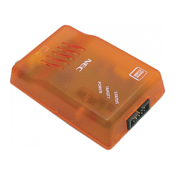
CHAPTER 2 NAMES OF PARTS This chapter provides the names of the QB-78K0MINI's parts. 2.1 Names of Parts in Main Unit Figure 2-1. Main Unit (Top View) Screw Figure 2-2. Main Unit (Side Views) (a) Left side (b) Right side... - Page 18 CHAPTER 2 NAMES OF PARTS Figure 2-3. External View of Board CLK1 USB1 LED1 LED2 LED3 User’s Manual U17029EJ3V0UM...
-
Page 19: Chapter 3 Hardware Settings And Functions
CHAPTER 3 HARDWARE SETTINGS AND FUNCTIONS In order to connect the QB-78K0MINI to the target system for debugging, a circuit for connecting the QB-78K0MINI to the target system must be created. For details, see the target device’s user’s manual. Remark Since the environment used for on-chip debugging is the same as the actual debugging environment, debugging is performed with the microcontroller installed in a system. -
Page 20: Hardware
Caution Be sure to turn off the QB-78K0MINI’s power supply before mounting or removing a clock in the clock socket for the target device. In addition, do not mount a clock in the clock socket when “System”... -
Page 21: Connectors For Qb-78K0Mini
CHAPTER 3 HARDWARE SETTINGS AND FUNCTIONS (e) Parts board mounted in CLK1 socket 3.1.3 Connectors for QB-78K0MINI The QB-78K0MINI’s connector CN1 (a two-row 2.54 pitch type connector, with reverse-insertion blocker) is described below. Note Pin No. Name IN/OUT Remark RESET_IN... -
Page 22: Display Devices
CHAPTER 3 HARDWARE SETTINGS AND FUNCTIONS 3.1.5 Display devices Three LEDs are included as status display devices. Name Display Function Remark LED1 STATUS RUN: Blinking (slow) (RUN, BREAK, DOWNLOAD) After break or debugger start: ON DOWNLOAD: Blinking (fast) Before starting debugger: OFF LED2 TARGET Before starting... -
Page 23: Qb-78K0Mini Equivalent Circuit
CHAPTER 3 HARDWARE SETTINGS AND FUNCTIONS 3.2.1 QB-78K0MINI equivalent circuit Figure 3-1. Equivalent Circuit • Supervisor side • QB78K0MINI side Note 74VHC125 RESET_OUT RESET_IN 74LV07 1 kΩ 100 kΩ PULL UP 3.3 kΩ 3.3 V 1 kΩ PULL UP 74LV07... -
Page 24: Target Reset Processing
FLMD0 Reset circuit Note 2 Notes 1. When QB-78K0MINI is connected FLMD0 is at high level, and when it is not connected FLMD0 is pulled down. 2. Connect a pull-down resistor of 470 Ω or higher. Remark All constants shown in this circuit are reference values. - Page 25 Buffer To RESET_IN To RESET_IN Caution The reset is driven from the QB-78K0MINI when a resistor is connected between RESET_IN and RESET_OUT and the QB-78K0MINI is connected. When the QB-78K0MINI is not connected, the reset is driven via the resistor and from within the target device.
-
Page 26: Target Connectors
CHAPTER 3 HARDWARE SETTINGS AND FUNCTIONS 3.4 Target Connectors The QB-78K0MINI’s target connector (a two-row 2.54 pitch type connector, with reverse-insertion blocker) is described below. Pins 9 and 10 should be left open on the target. • Recommended connectors: (straight) HIF3FC-10PA-2.54DSA (manufactured by Hirose Electric Co., Ltd.) (right angle) HIF3FC-10PA-2.54DS (manufactured by Hirose Electric Co., Ltd.)) -
Page 27: Connection Circuit Examples
CHAPTER 3 HARDWARE SETTINGS AND FUNCTIONS 3.5 Connection Circuit Examples The following are examples of circuits required when connecting the QB-78K0MINI to the target system. For details, see the target device’s user’s manual. Figure 3-6. Connection Circuit Example (When QB-78K0MINI Is Not Used) - Page 28 CHAPTER 3 HARDWARE SETTINGS AND FUNCTIONS Note 1 Figure 3-8. Connection Circuit Example (When Using QB-78K0MINI: Ports A and B Are Used) Target device QB-78K0MINI target connector FLMD0 FLMD0 Note 2 Target reset RESET IN RESET RESET OUT Note 3...
-
Page 29: Connections And Startup Procedure
CHAPTER 3 HARDWARE SETTINGS AND FUNCTIONS 3.6 Connections and Startup Procedure 3.6.1 Mounting clock The following describes mounting the clock to be supplied to the target system in the QB-78K0MINI. (1) Loosen the QB-78K0MINI’s screw. (2) Remove the cover. Use the interface connector side as a reference point when lifting the USB connector side. - Page 30 CHAPTER 3 HARDWARE SETTINGS AND FUNCTIONS The product appears as shown below when the cover has been removed. Clock socket (3) Insert an oscillator or oscillation circuit. Insert an oscillator or oscillation circuit for the clock to be supplied to the target system into the clock socket. User’s Manual U17029EJ3V0UM...
- Page 31 CHAPTER 3 HARDWARE SETTINGS AND FUNCTIONS (4) Replace the cover. Make sure that the cover is aligned with the two tabs on the interface connector side. Tabs (5) Close the cover and tighten the screw. This completes the clock mounting procedure. User’s Manual U17029EJ3V0UM...
-
Page 32: Connecting Qb-78K0Mini To Related Devices
USB driver, OCD Checker, and device files in the host machine. (1) Attach the QB-78K0MINI connection cable (QB-78K0MINI side) Align the ridge in the QB-78K0MINI connection cable socket with the groove in the QB-78K0MINI’s interface connector for preventing reverse insertion and insert the socket into the connector. - Page 33 (2) Attach the QB-78K0MINI connection cable (self-check board or target system side) Align the ridge in the QB-78K0MINI connection cable’s socket with the groove in the target connector on the self-check board or target system side for preventing reverse insertion and insert the socket into the connector.
- Page 34 CHAPTER 3 HARDWARE SETTINGS AND FUNCTIONS (3) USB interface cable connection (QB-78K0MINI side) Connect the USB interface cable’s MINI-B connector to the QB-78K0MINI’s USB connector. MINI-B connector User’s Manual U17029EJ3V0UM...
- Page 35 CHAPTER 3 HARDWARE SETTINGS AND FUNCTIONS (4) USB interface cable connection (host machine side) Connect the USB interface cable’s A connector to the host machine’s USB port. A connector side User’s Manual U17029EJ3V0UM...
- Page 36 (5) Power-on (a) When using a self-check board After connecting the USB interface cable to the host machine, turn on the power to the QB-78K0MINI and the self-check board (the QB-78K0MINI’s TARGET and POWER LEDs are ON and the self-check board’s LED1 is ON).
- Page 37 When the USB interface cable is connected to the host machine, only the QB-78K0MINI’s POWER LED is ON (the QB-78K0MINI’s power is ON and the target system’s power is OFF). When turning on the power to the target system, POWER LED is ON (the QB-78K0MINI’s power is ON and the target system’s power is ON).
-
Page 38: Disconnecting Qb-78K0Mini From Related Devices
(2) Turn off the power to the target system (if using a target system). (3) Remove the USB interface cable from the QB-78K0MINI and the host machine. (4) Remove the QB-78K0MINI connection cable from the QB-78K0MINI and from either the target system or the self-check board. -
Page 39: Cautions On Creating Target System
CHAPTER 3 HARDWARE SETTINGS AND FUNCTIONS 3.8 Cautions on Creating Target System Be sure to note the following cautions when creating the target system. • Do not place X1 and X2 next to each other on the target board. If the layout requires this, they should be made as short as possible. -
Page 40: Chapter 4 Cautions On Use Of Self-Check Board
CHAPTER 4 CAUTIONS ON USE OF SELF-CHECK BOARD 4.1 Functions of Self-check Board (1) Self check The OCD Checker can be used to perform self checking of the QB-78K0MINI. (2) Operation check Start the integrated debugger and download the user program, then check the operation. - Page 41 CHAPTER 4 CAUTIONS ON USE OF SELF-CHECK BOARD Figure 4-1. Circuit Diagram of Self-check Board User’s Manual U17029EJ3V0UM...
-
Page 42: Self-Check Board Recovery
Write ports: 3-wire handshake mode or 3-wire (SIO-ch0) mode Serial transfer rate: 625 kHz Cautions 1. To avoid signal conflicts, do not connect the flash programmer to the QB-78K0MINI. 2. When connecting the flash programmer, connect the programmer’s cable to the FP1 connector. - Page 43 CHAPTER 4 CAUTIONS ON USE OF SELF-CHECK BOARD (2) Enter the settings for the flash programmer. Figure 4-3. Example of Settings for PG-FP4 (3) Perform a chip erase operation. User’s Manual U17029EJ3V0UM...
-
Page 44: Chapter 5 Restrictions
CHAPTER 5 RESTRICTIONS The restrictions are described below. A delay period of about 50 µs from cancellation of a target reset (RESET_IN) to cancellation of a target device reset (RESET_OUT) (the period from when the target reset (RESET_IN) becomes low to when the target device reset (RESET_OUT) becomes high) is required for mode setting. - Page 45 • There is a communication problem due to a bug in the microcontroller mounted on the self-check board when the QB-78K0MINI operates on the Ring-OSC. The debugger takes a measure to avoid this problem by forcibly switching to the main clock when a break occurs, and re-switches to the Ring-OSC when the program is executed.
-
Page 46: Chapter 6 Cautions
(3) Values specified by linker option -go Among the reserved areas used by QB-78K0MINI, the following areas can be secured using the linker option -go. Addresses 0x02 and 0x03 (Size of program specified from address 0x8F) +1 Specify the -go option default value, 256, for the program size for on-chip debugging. - Page 47 Values other than 0x02 and 0x03 cannot be written to address 0x84. The processing is performed so that 0x00 (the value set to disable QB-78K0MINI connection) or any other illegal value is not written. When setting 0x00, use a flash memory programmer (such as PG-FP4).
- Page 48 PD78F0148HD. In this case, cluster 0 (0000H to 0FFFH) includes the area described in (1) Reserved area used by QB-78K0MINI (a) Flash memory area, so data in these areas must be copied to cluster 1 (1000H to 1FFFH), that is, the area in which 1000H is added to the address.
- Page 49 CHAPTER 6 CAUTIONS MOV PFCMD,#0A5H MOV FLPMC,#1H ← <1> MOV FLPMC,#0FEH MOV FLPMC,#1H ----------------------- From this position ← <2> ↑ CALL !08100H MOV PFCMD,#0A5H MOV FLPMC,#0H Mode A1 MOV FLPMC,#0FFH MOV FLPMC,#0H ← <3> ↓ ----------------------- To this position The section between <2> and <3> is in self programming mode A1 (including A2). Step execution or a break by STOP or a breakpoint cannot be performed by the debugger in this section.
- Page 50 , when "System" is selected for "Monitor Clock" in the Configuration dialog box, the clock source of the device is changed to the clock from QB-78K0MINI during a break. If the peripheral emulation function does not stop (by selecting "Non Break" for "Peripheral Break"), due to clock changes, timing may differ from the timing in the actual operation.
- Page 51 <5> If RRM is executed during a standby state, the standby state is released. <6> The RRM function is supported in QB-78K0MINI with control code B or later. Notes 1. Devices in which “OCD Control Code V1.xx” is displayed by selecting [About…] from the [Help] menu in the ID78K0-QB [About…] from the...
-
Page 52: Caution On Option Byte
Emulation of the option byte which is assigned to addresses 0x80 to 0x83 (refer to the user’s manual of the device used for the address and function) is performed as follows. When QB-78K0MINI is connected: The option byte setting reflected in emulation. -
Page 53: Appendix A On-Chip Flash Memory Security Functions
• The values of addresses 0x85 to 0x8E comprise the 10-byte ID code. • Bits 0 and 1 at address 0x84 are the use enable flag bits for the QB-78K0MINI (“00b” = use prohibited, any other value = use enabled). -
Page 54: Appendix B Revision History
Version Revised Points Applicable Chapter Second Change of Figure 1-1 External Dimensions of QB-78K0MINI CHAPTER 1 GENERAL Table 1-1 Product Specifications Addition and change of description 1.3 System Configuration Addition and change of description Addition of Figure 1-5 Package Contents <7> and <8>...
Need help?
Do you have a question about the QB-78K0MINI and is the answer not in the manual?
Questions and answers