Table of Contents
Advertisement
Advertisement
Table of Contents

Related Manuals for Vatech PaX-i3D Smart


Summary of Contents for Vatech PaX-i3D Smart
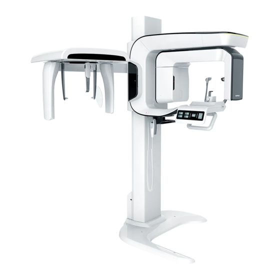
- Page 1 (PHT-30LFO) Installation Manual Version 1.0.0 HARDWARE and SOFTWARE E n g l i s h...
- Page 4 Notice to the Installers Notice This manual covers the installation procedures for the PaX-i3D Smart dental X-Ray unit. An installation manual and user manual are shipped with each hardware unit. Brand name: PaX-i3D Smart (Model: PHT-30LFO) Manufactured by : VATECH Co., Ltd.
- Page 5 Failure to read and understand the information provided in this manual may result in physical injury, damage to the equipment or equipment failure. Please read each CHAPTER in its entirety and understand the information therein before attempting any of the installation procedures. Pax-i3D Smart(PHT-30LFO) Installation Manual...
- Page 6 Radiation symbols indicate a possible danger from exposure to radiation. Important symbols indicate a compulsory action or instruction. ESD susceptibility symbols indicate that an item is susceptible to damage from electrostatic discharges. Pax-i3D Smart(PHT-30LFO) Installation Manual...
- Page 7 Notice to the Installers Never touch or hold the sensor or tube head areas while moving, installing or operating the equipment. Sensor Tube head Handle frame Pax-i3D Smart(PHT-30LFO) Installation Manual...
- Page 8 Do not step on the base unit while installing or operating the equipment. Do not use the electrical power drill during installation unless it is allowed to do so. Recommended holding area during transportation(OK) Four installers are required to install the equipment safely. Pax-i3D Smart(PHT-30LFO) Installation Manual...
- Page 9 Notice to the Installers Locations of the Power and Emergency Switches EMERGENCY SWITCH ON/OFF SWITCH Pax-i3D Smart(PHT-30LFO) Installation Manual...
- Page 10 5. Do not connect any items or equipment to this system which are not part of the system: IEC60601-1-1 (3 edition: 2005). 6. Any equipment not approved by VATECH must comply with the applicable standards: IEC 60950-1 (2 edition: 2005) for IT equipment (Ex: PC) and IEC 60601-1 (3 edition: 2005) for medical electrical equipment.
- Page 11 2 m (7 feet) away from the X-Ray when pressing the exposure switch and observe the patient and capture-progression. 5. Operators must provide protective clothing to the patient before X-Ray capturing. Pregnant women must consult with a doctor prior to being exposed to an X-Ray. Pax-i3D Smart(PHT-30LFO) Installation Manual...
- Page 12 2. Any equipment not provided by VATECH can be connected when the following standards are complied with: IEC 60950-1 and IEC 60601-1 3. The electrical installation shall comply with local code requirements for electro-medical systems: IEC 60364-7-710: 2002.
-
Page 13: Table Of Contents
Fixing the base (Optional) ....................59 Removing the Transportation Safety Bolts ..............62 Leveling the Equipment ....................64 Tightening the Bolts firmly ....................66 Completing Miscellaneous Works ............ 67 Assembling Various Covers .....................68 Assembling Temple and Chin Supports ................70 Installing the Switch Holders ...................71 Pax-i3D Smart(PHT-30LFO) Installation Manual... - Page 14 A. Installing the Warning Lamp and Door Interlock Switch .............144 B. Installing the Emergency Switch ..................147 C. Limiting the Column Height ....................148 D. Connecting the Third-party Exposure Switch(Optional) .............152 E. Checking PC BIOS Settings ....................153 F. Installation checklist ......................154 Pax-i3D Smart(PHT-30LFO) Installation Manual...
-
Page 15: Introduction
Introduction Manufacturer’s Liability ........... 16 Customer’s Responsibility ..........16 Marks & Symbols ............17 Standards and Regulations ..........18... -
Page 16: Manufacturer's Liability
1 Introduction Manufacturer’s Liability As the manufacturer, VATECH assumes liability for the safe and reliable installation and operation of this equipment only when: ● Equipment installation, including software installation, was carried out by an authorized agent in accordance with this installation manual. -
Page 17: Marks & Symbols
This symbol warns the user to take precautions when MCU board dealing with electronic components which are sensitive to packaging static charges This symbol indicates that this equipment is classified as a CLASS 1 LASER PRODUCT in accordance with IEC Label 60825-1 ED.1 regulations. Pax-i3D Smart(PHT-30LFO) Installation Manual... -
Page 18: Standards And Regulations
Directive for Medical Devices 93/42/EEC as amended by 2007/47/EC as a class IIb device. B. Classification: (IEC60601-1 6.1) Protection against the ingress of water: IEC60529 edition 2.1 Ordinary Equipment: IPX0 Protection against electric shock: Class Ⅰ equipment, Type B Applied Parts Pax-i3D Smart(PHT-30LFO) Installation Manual... -
Page 19: Choosing An Installation Site
Choosing an Installation Site Room Requirements ............20 Specifications for Electrical Installation ......23 Electrical Requirements ..........23 Temperature and Humidity ..........25 Exposure Switch Installation Options ......25 Installation Versions ............27 Installing the Warning Lamp and Door Interlock Switch ... 28 Installing the Emergency Stop Switch ...... -
Page 20: Room Requirements
2500/98.4” 1321(52) 470(18.5) 1165(45.9) 1914(75.4) With Cephalometric unit (optional): 2,500mm x 2,500mm/98.4" x 98.4" or wider Pax-i3D Smart(PHT-30LFO) Installation Manual... - Page 21 2 Choosing an Installation Site 1700/67” 1165(45.9) Without Cephalometric unit: 2,500mm x 1,700mm/98.4" x 67" or wider Pax-i3D Smart(PHT-30LFO) Installation Manual...
- Page 22 Lead thickness: ≥1 mm ● Maintain visible contact with the patient and a clear view of indicators such as the warning lamp and imaging status on the PC. Pax-i3D Smart(PHT-30LFO) Installation Manual...
-
Page 23: Specifications For Electrical Installation
AC100-240 V ● The input line voltage depends on the local electrical distribution system. ● Allowable input voltage fluctuation requirement: ± 10 %. Frequency 50/60 Hz Phase single Power rating (maximum power consumption) Max.2.2 kVA (during exposure) Pax-i3D Smart(PHT-30LFO) Installation Manual... - Page 24 1. To assure line voltage quality, a separate 3-core grounded power cable connected directly to central distribution panel with over-current circuit breaker rated for 20/15A must be used. 2. The mains resistance should not exceed 0.5 Ω. 3. This equipment should be connected to the earthed outlet. Pax-i3D Smart(PHT-30LFO) Installation Manual...
-
Page 25: Temperature And Humidity
Exposure Switch Installation Options There are three options for installation, depending on the configuration of the site. Nevertheless, the 2 option is preferred. Option No. 1:The user operates the exposure switch from inside the X-Ray room. PaX-i 3D Smart Pax-i3D Smart(PHT-30LFO) Installation Manual... - Page 26 PaX-i 3D Smart Option No. 3: The 3rd party exposure switch (not VATECH’s) is used on demand of the customers. For this scenario, see the Appendix D “Connecting the 3 party exposure switch” for details.
-
Page 27: Installation Versions
2 Choosing an Installation Site Installation Versions Base-mount type 30 cm/12" or wider 16 cm/7" or wider Wall mount type 30 cm/12" or wider 16 cm/7" or wider Pax-i3D Smart(PHT-30LFO) Installation Manual... -
Page 28: Installing The Warning Lamp And Door Interlock Switch
● Install the emergency stop switch along the main power cable in the central distribution panel. ● Install this switch so that it is within easy reach of the operator but cannot be accidentally pressed. ● The switch must be a fool-proof model. Pax-i3D Smart(PHT-30LFO) Installation Manual... -
Page 29: Before Installing The System
Before Installing the System Required Tools ............... 30 Checking the ShockWatch and TiltWatch Indicators ..32 Unpacking the Boxes............33 Checking the Parts ............41... -
Page 30: Required Tools
3 Before Installing the System Required Tools The following tools are necessary to install the PaX-i3D Smart. Item Figure Size Wrench set 1.5 mm-10 mm/0.06”-0.4” Allen wrench set 1 . 5 m m - 1 0 m m (0.05"-0.4") T-shaped hex wrench 6 mm-10 mm/0.24”-0.4”... - Page 31 3 Before Installing the System Item Figure Size Anti-static glove Knife Tape ruler 5 m: for wall mounted type Marker pen(thick tip) For wall mounted type Hammer For wall mounted type Multi-meter Hammer drill For wall mounted type Pax-i3D Smart(PHT-30LFO) Installation Manual...
-
Page 32: Checking The Shockwatch And Tiltwatch Indicators
3. Locate the ShockWatch and TiltWatch indicators and check if they have been activated. If either the packaging is damaged or the ShockWatch or TiltWatch indicators have been activated, please do not open the package and immediately contact the shipping company, agent or VATECH. TiltWatch Pax-i3D Smart(PHT-30LFO) Installation Manual... -
Page 33: Unpacking The Boxes
3 Before Installing the System Unpacking the Boxes All packaging and Styrofoam used to ship this equipment is recyclable. Return the packaging to VATECH representatives or dispose of it in compliance with the legal regulations of your country. Box No.1: Main box ●... - Page 34 2. Separate the top cover after removing the strapping bands. 3. Lift up a small distance and remove the side covers. A: PC system (Optional) B: PE foam C: PE foam D: Accessory and part box1 E: Accessory and part box2 Bottom Pax-i3D Smart(PHT-30LFO) Installation Manual...
- Page 35 3 Before Installing the System 4. Put the PC system(optional) down on the floor. 5. Put the Accessory boxes(D,E) on the floor. 6. Separate 2 side PE(B,C) foams. Pax-i3D Smart(PHT-30LFO) Installation Manual...
- Page 36 3 Before Installing the System View after the removal of the EPS foams Pax-i3D Smart(PHT-30LFO) Installation Manual...
- Page 37 3 Before Installing the System Box No. 2: Base unit Component Size(mm/inch) Weight(kg/lbs) 1035(L) x 1025(W) x 185(H) / Base 47/103 40.7"(L) x 40.3"(W) x 7.3"(H) 185mm/7.3" Pax-i3D Smart(PHT-30LFO) Installation Manual...
- Page 38 3 Before Installing the System Removing the cover 1. Open the box cover, the base cover appears. 2. Remove the base cover. Pax-i3D Smart(PHT-30LFO) Installation Manual...
- Page 39 Box No. 3: Cephalometric unit (Optional) Component Size(mm/inch) Weight(kg/lbs) 1605(L) x 875(W) x 900(H) / Cephalometric unit 50/110 63.2"(L) x 34.4"(W) x 35.4"(H) 900mm/35.4" Removing the cover 1. Open the box cover, starting with the top cover. Pax-i3D Smart(PHT-30LFO) Installation Manual...
- Page 40 3 Before Installing the System 2. Remove the top Styrofoam cover. The view after removal of the Styrofoam. Pax-i3D Smart(PHT-30LFO) Installation Manual...
-
Page 41: Checking The Parts
3 Before Installing the System Checking the Parts Location layout of the parts and accessories 1,2,3,4 32, 33 Pax-i3D Smart(PHT-30LFO) Installation Manual... - Page 42 STICKER SCREWS M3X16 Yes □ No □ PLATE HAND Yes □ No □ REST CEPH BLOCK ACRYL FIX Yes □ No □ BOLT CEPH Option KNOBS Yes □ No □ HANDREST Yes □ No □ STICKER Pax-i3D Smart(PHT-30LFO) Installation Manual...
- Page 43 CHIN Yes □ No □ SUPPORT TMJ/SINUS CHIN Yes □ No □ SUPPORT CAP CEPH CAP: EAR ROD (2: on the Yes □ No □ equipment) SILICON COVER: CEPH: extra Yes □ No □ NASAL POSITIONER Pax-i3D Smart(PHT-30LFO) Installation Manual...
- Page 44 Column To Yes □ No □ w/spring and Base flat washers WRENCH BOLT M8 x 45 Yes □ No □ M8 x 20 WRENCH BOLT Yes □ No □ w/spring washer FLAT WASHER Yes □ No □ Pax-i3D Smart(PHT-30LFO) Installation Manual...
- Page 45 Yes □ No □ Left blank intentionally UP/DOWN Yes □ No □ SWITCH UP/DOWN SWITCH Yes □ No □ HOLDER Optional DOUBLE SIDED Yes □ No □ SITCKER SCREWS M4 x 10 Yes □ No □ Pax-i3D Smart(PHT-30LFO) Installation Manual...
- Page 46 NUTS Yes □ No □ WALL Yes □ No □ BRACKET BASE FRONT Yes □ No □ COVER COLUMN BACK Yes □ No □ COVER BASE FRONT COVER & COLUMN BACK COVER location Accessory Box Base Front Cover & Column Back Cover Pax-i3D Smart(PHT-30LFO) Installation Manual...
-
Page 47: Installing The Equipment: Floor Standing (Optional)
Installing the Equipment: Floor Standing (Optional) Assembling the Base and Main Units ......48 Installing the CEPH Unit (Optional) ........51 Connecting the Cables to the Equipment ......54 Installing the Wall and Column Brackets ......55 Fixing the base (Optional) ..........59 Removing the Transportation Safety Bolts ...... -
Page 48: Assembling The Base And Main Units
E s p e c i a l l y, t h e f i b e r o p t i c c a b l e i s very sensitive to the external impact. Allen 6 mm/0.24” wrench Pax-i3D Smart(PHT-30LFO) Installation Manual... - Page 49 4. Fix the column unit to the base unit. Allen wrench 8 mm/0.31” M10 x 25 w/spring and flat WRENCH washers BOLT Part No.: 23 6 PCS Pax-i3D Smart(PHT-30LFO) Installation Manual...
- Page 50 Removing the Transportation Handle 1. Move the equipment to installation location as close as possible. 2. Remove the upper carrying handle. Allen wrench 6 mm/0.24” One installer should hold the handle, while the other is removing the bolts. Pax-i3D Smart(PHT-30LFO) Installation Manual...
-
Page 51: Installing The Ceph Unit (Optional)
4 studs. M a k e s u r e t h e C E P H c a b l e s f r o m t h e equipment go through the CEPH arm hole. Pax-i3D Smart(PHT-30LFO) Installation Manual... - Page 52 - Ensure that the caps of the fiber optic cable be removed. - Do not touch the tip of the fiber optic cable to prevent it from being dirty. - Insert the fiber optic cable fully until the click sound is heard. SC CEPH Pax-i3D Smart(PHT-30LFO) Installation Manual...
- Page 53 5. Put the cables inside the CEPH Arm and assemble the CEPH arm cover by using two flat head screw. CEPH Part No. COVER M3 x 6 FLAT Part No. HEAD SCREW 2 PCS Cross head screw driver w/ mm/0.24” magnetic Pax-i3D Smart(PHT-30LFO) Installation Manual...
-
Page 54: Connecting The Cables To The Equipment
2. Assemble the COLUMN BACK COVER with four truss bolts. Ensure the cables go through the COLUMN BACK COVER holes. M4 x 8 Truss bolts Part No.: 27 4 pcs Cross head screw driver with magnetic tip COLUMN BACK COVER hole Pax-i3D Smart(PHT-30LFO) Installation Manual... -
Page 55: Installing The Wall And Column Brackets
M5 x 12 FLAT HEAD Part No.: 29 SCREWS 4 PCS Cross head screw driver with magnetic Combining column and wall brackets 1. Prepare the wall bracket. WALL Part No.: 36 BRACKET Pax-i3D Smart(PHT-30LFO) Installation Manual... - Page 56 Marking 4 points on the wall 1. Move the equipment to the installation site as close as possible 2. Adjust the distance between the wall and equipment by moving it slightly, so that the wall bracket touches the wall. Variable distance Pax-i3D Smart(PHT-30LFO) Installation Manual...
- Page 57 2. Remove the debris and clean the holes using the dust pump. 3. Anchor the bolts with the hammer.Verify that the anchors are secured M8 Size WRENCH Part No.: 34 BOLTS Wall: 4 PCS Hammer drill Pax-i3D Smart(PHT-30LFO) Installation Manual...
- Page 58 4 Installing the Equipment: Floor Standing (Optional) Combining the equipment with the anchor bolts 1. Place the equipment properly in its position and secure it with the nuts. Pax-i3D Smart(PHT-30LFO) Installation Manual...
-
Page 59: Fixing The Base (Optional)
2 locations on the floor. 2. Drill the floor holes of size 12mm x 30mm (depth) using the concrete hammer drill. 3. Remove the debris and clean the holes using the dust pump. Pax-i3D Smart(PHT-30LFO) Installation Manual... - Page 60 4. Remove nuts and washers, put the anchor bolts into the holes. 5. Secure the anchor bolts with the hammer. 6. Place the base unit combined equipment on the proper position, lock the nuts and washers using ratchet wrench. Pax-i3D Smart(PHT-30LFO) Installation Manual...
- Page 61 4 Installing the Equipment: Floor Standing (Optional) Wooden floor M12 x 70 Wood screws Part No.: 34 2 PCS Hammer drill L=200mm7.9 1. Secure the base unit using the wood screws. Pax-i3D Smart(PHT-30LFO) Installation Manual...
-
Page 62: Removing The Transportation Safety Bolts
Removing the Transportation Safety Bolts 1. Remove the semi-clear tape on the both sides Be careful not to scratch the cover. 2. Remove the vertical frame cover. 3. Remove four safety bolts. Wrench bolts Allen wrench 6 mm/0.24” Pax-i3D Smart(PHT-30LFO) Installation Manual... - Page 63 4 Installing the Equipment: Floor Standing (Optional) 4. Remove two column fixing bolts. Allen wrench 5 mm/0.2" Pax-i3D Smart(PHT-30LFO) Installation Manual...
-
Page 64: Leveling The Equipment
1. Prepare the spirit level. 2. Position the rotating unit so that the X-Ray tube head faces the front. Tube head 3. Turn all eight screws on the base plate unit clockwise until they touch the ground. Pax-i3D Smart(PHT-30LFO) Installation Manual... - Page 65 3. Place the spirit level on the vertical frame, as shown in the following figure. 4. Adjust the screws until bubble of spirit level centers (level), by turning the front and/or back screws clockwise or vice versa. Pax-i3D Smart(PHT-30LFO) Installation Manual...
-
Page 66: Tightening The Bolts Firmly
4 Installing the Equipment: Floor Standing (Optional) Tightening the Bolts firmly 1. Tighten the joint bracket bolts. Allen wrench 6 mm/0.24” Monkey wrench Pax-i3D Smart(PHT-30LFO) Installation Manual... -
Page 67: Completing Miscellaneous Works
Completing Miscellaneous Works Assembling Various Covers ..........68 Assembling Temple and Chin Supports ......70 Installing the Switch Holders ........... 71... -
Page 68: Assembling Various Covers
(Part No.: 27). M4 x 8 Part NO . : Truss Bolts 6 PCS Cross head L=200 screw driver w/ mm/7.9 magnetic tip 2. Put the six hole caps on the vertical frame cover holes(Part No.:16). Pax-i3D Smart(PHT-30LFO) Installation Manual... - Page 69 1. Assemble the base cover and fix it with three truss bolts(Part No: 26). 2. Cover 3 holes on the base with three silicon caps(Part No: 17) Base front cover 1. Assemble the base front cover to the column. Pax-i3D Smart(PHT-30LFO) Installation Manual...
-
Page 70: Assembling Temple And Chin Supports
5.2 Assembling Temple and Chin Supports 1. Insert the normal bite block into the chinrest. Part No.: 13 BITE BLOCK: NORMAL 1 PCS 2. Insert the temple supports and ear rod caps. Part No.: 5 TEMPLE SUPPORT 2 PCS(R, L) Pax-i3D Smart(PHT-30LFO) Installation Manual... -
Page 71: Installing The Switch Holders
No.:33) to the unit and hang it on the switch holder. Exposure switch holder 1. Locate the exposure switch holder(Part No.:2) with a sticker and two screws. 2. Install the switch holder on the wall at the appropriate height using two screws. Pax-i3D Smart(PHT-30LFO) Installation Manual... - Page 72 This page is intentionally left blank.
-
Page 73: Setting Up Pc
Setting up PC Direct Connection Diagram ..........74 The Recommended PC Requirements ......75 Installing the Internal Peripherals ........78 Connecting the Cables to PC ......... 80... -
Page 74: Direct Connection Diagram
Warning lamp Door interlock (Optional) Fiber Optic Cable & Ethernet cable: Used to transfer image data to the PC. Warning system panel: Used to provide a visible indicator: light when the equipment is irradiating X-Ray Pax-i3D Smart(PHT-30LFO) Installation Manual... -
Page 75: The Recommended Pc Requirements
AVR (automatic voltage regulator) is strongly recommended to keep the line voltage stable The PC system provided with the PaX-i3D Smart undergoes the rigorous test for software compatibility before shipping. Therefore any later changes to the... - Page 76 It is mandatory to meet the PC system requirements specified in the table above. In Windows 8, disable Windows Defender. When Windows Defender is not enabled, Windows 8 is not protected from malware and virus. Pax-i3D Smart(PHT-30LFO) Installation Manual...
- Page 77 3. Settings tab → Excluded files and locations → Click Browse and navigate to C:\VCaptureSW → click Add. Or, Settings tab → Administrator → Uncheck the Use this program check box to disable Windows Defender. 4. Click the Save changes button to confirm the changes. Pax-i3D Smart(PHT-30LFO) Installation Manual...
-
Page 78: Installing The Internal Peripherals
Whenever handling the fiber optic frame grabber board: 1. Wear the ant-static glove. 2. Do not wear the likes of a thick jacket. The following figures and descriptions are based on the PC model Z420 from Pax-i3D Smart(PHT-30LFO) Installation Manual... - Page 79 Dark calibration data acquisition or noisy image acquisition. 4. Put the slot holder back to its initial position. The end result after the peripheral installation CEPH CT/PANO The end result after the peripheral installation Pax-i3D Smart(PHT-30LFO) Installation Manual...
-
Page 80: Connecting The Cables To Pc
Connect the regular cables for PC: keyboard, mouse, and video in advance. The following figures and descriptions are based on the PC model Z420 from HP. 1. Connect the fiber optic cable (Part No.: 21) 2. Insert the 3D viewer USB key(Part No.:1) into a USB port. Pax-i3D Smart(PHT-30LFO) Installation Manual... - Page 81 6 Setting up PC The end result after connections are finished PANO/CT PANO/CT/CEPH(Scan) Pax-i3D Smart(PHT-30LFO) Installation Manual...
- Page 82 This page is intentionally left blank.
-
Page 83: Setting Up Pc's Environment Variables
Setting up PC's Environment Variables Before Beginning ............84 Checking PC BIOS Settings ........... 84 Turning the firewall off ............ 85 Setting up the Power Mangement Options ....87 Turning off the User Account Control ......89 Setting Folder exclusions with Anti-virus Software ..91... -
Page 84: Before Beginning
Checking PC BIOS Settings 1. The PC is shipped, with its BIOS settings, as specified in the Appendix E: Checking PC BIOS Settings. Before proceeding to the next sections, check the BIOS status. Pax-i3D Smart(PHT-30LFO) Installation Manual... -
Page 85: Turning The Firewall Off
Windows Firewall by using the following procedure 1. From the desktop, click Start → Control Panel 2. Click the View by field on the upper right corner and select Large icons. 3. Double click on the Windows Firewall. Pax-i3D Smart(PHT-30LFO) Installation Manual... - Page 86 7 Setting up PC’s Environment Variables 4. Select the Turn Windows Firewall on or off. 5. Select the Turn off Windows Firewall for both settings: Work and Public networks. 6. Click OK to apply the settings. Pax-i3D Smart(PHT-30LFO) Installation Manual...
-
Page 87: Setting Up The Power Mangement Options
Windows operating system. Disabling the screen saver From the desktop, 1. Click the right mouse button and select Personalize. 2. Locate and click the screen saver. 3. Select None in the pull-down menu. 4. Click OK. Pax-i3D Smart(PHT-30LFO) Installation Manual... - Page 88 7 Setting up PC’s Environment Variables Selecting the power options: monitor and system 1. Go to the Control Panel. 2. Double click on the Power Options icon. 3. Select “Choose when to turn off the display”. Pax-i3D Smart(PHT-30LFO) Installation Manual...
-
Page 89: Turning Off The User Account Control
4. Select “Never” for both fields. 5. Click “Save changes”. Turning off the User Account Control 1. Open the control panel of Windows. 2. Click the User Account icon. 3. Click on the ‘Change User Account Control settings’. Pax-i3D Smart(PHT-30LFO) Installation Manual... - Page 90 7 Setting up PC’s Environment Variables 4. Disable the UAC by moving the slider bar down to the bottom, Never notify. 5. Click ‘OK’ and restart the PC. Pax-i3D Smart(PHT-30LFO) Installation Manual...
-
Page 91: Setting Folder Exclusions With Anti-Virus Software
If you are using anti-virus software on your PC, you must exclude those files from all scans performed by the anti-virus software. For the PaX-i3D Smart, the following folder and files should be excluded with the virus scan. Files... - Page 92 This page is intentionally left blank.
-
Page 93: Installing Software
Installing Software Before Beginning ............94 Software Installation Flow ..........95 Installing Image Viewer Program ........95 Installing the installShield ..........96 Setting up the User-specific Information ....... 106 8.5.1 When EasyDent4 is installed ....... 106 8.5.2 When EzDent -i is installed ......... 113 8.5.3 Configuring the parameters ........ -
Page 94: Before Beginning
Perform virus scan for the PC and InstallShield program with the anti-virus program prior to proceeding with its installation. Do not install the programs irrelevant to image acquisition and view together with imaging program on the same PC. There may be subtle conflicts between them. Pax-i3D Smart(PHT-30LFO) Installation Manual... -
Page 95: Software Installation Flow
Installing Image Viewer Program One of the image viewer programs among :EasyDent4, EzDent- i, or 3th party program must be installed at this time. For the details on the installation procedures, refer to the corresponding manual. Pax-i3D Smart(PHT-30LFO) Installation Manual... -
Page 96: Installing The Installshield
1. Turn On the PC and Equipment if they are not yet. 2. Insert the CD into CD-ROM drive. and then perform virus scan for PC and Install CD 3. Go to the InstallShield folder. Then run VTConsoleSW.exe 4. The following screen will appear and click Next. Pax-i3D Smart(PHT-30LFO) Installation Manual... - Page 97 8 Installing Software 5. Select the equipment mode: PaX-i3D Smart and click Next. 6. Select the modality and click Next. Note that if the CEPH feature comes with the equipment, also check the CEPH. 7. Select the CT sensor type: WidePano and click Next.
- Page 98 14. Select the drivers to be installed. For the first time installation, select all. 15. The following figure displays the information entered so far. If necessary, you can modify it by clicking Back button. Click Install to continue. Now extracting the files in the folder C:/VCaptureSW/. Pax-i3D Smart(PHT-30LFO) Installation Manual...
- Page 99 8 Installing Software Installing the DICOM viewer 1. Click Next to install DICOM viewer. 2. Select “I accept the terms of the license agreement” and click Next. 3. Enter the names of user and clinic and click Next. Pax-i3D Smart(PHT-30LFO) Installation Manual...
- Page 100 8 Installing Software 4. From the following screen, click Install. 5. Click Finish to finish. Pax-i3D Smart(PHT-30LFO) Installation Manual...
- Page 101 8 Installing Software Installing the DirectX 1. Now installing the DirectX: select “I accept the agreement”. 2. Click Next to continue. Now installing… 3. Click Finish. Pax-i3D Smart(PHT-30LFO) Installation Manual...
- Page 102 2. Click Install to install AnyGrabber card driver and VirtualSerial driver. 3. If Windows Security pop-up window appears, click ‘Install' 4. When the system restart required dialog box appears, click Yes or click No and restart the system later Pax-i3D Smart(PHT-30LFO) Installation Manual...
- Page 103 8 Installing Software Installing the HASP License Manager 1. From the welcome message, click Next. 2. Select “I accept license agreement”, followed by Install. 3. Leave as default from the following message. Pax-i3D Smart(PHT-30LFO) Installation Manual...
- Page 104 8 Installing Software 4. Select the folder where the files are copied to and click Next. 5. Select the program group. Leave it at default and click Next. 6. Click ‘Yes’ to restart the program. Ensure that the program should be restarted, with the HASP key being inserted into the USB port on PC. Pax-i3D Smart(PHT-30LFO) Installation Manual...
- Page 105 1. Locate the file: PaX-i3D Smart_Install_Log.txt on the desktop. 2. Open it to check the file. You can find out that all components are installed. 3. Go to the section 8.5 Setting up the User-specific Information. Pax-i3D Smart(PHT-30LFO) Installation Manual...
-
Page 106: Setting Up The User-Specific Information
EzDent- i : section 8.5.2 When EzDent -i is installed 8.5.1 When EasyDent4 is installed Running the image viewer 1. Run the image viewer. On your desktop, double-click EasyDent or click Start → All Programs → EasyDent. The EasyDent main window will be displayed. Pax-i3D Smart(PHT-30LFO) Installation Manual... - Page 107 3. Check ‘ Select capture mode for Dental CT’ select the NCSW. 4. Click Apply 5. When the following message appears, click OK to restart the program. 6. Re-run the EasyDent program and check the change has been reflected. Pax-i3D Smart(PHT-30LFO) Installation Manual...
- Page 108 2. Enter the required patient information. Chart Number, First Name , and Last Name are required fields which must be filled in. All other fields are optional, but it is recommended that they be filled 3. Click Add to save the patient record. Pax-i3D Smart(PHT-30LFO) Installation Manual...
- Page 109 2. Check the Terms and Conditions and click Next. 3. Enter the required information and click Next. For the console PC connected to the internet, go to no. 4. And for the console PC not connected to the internet, go to no. 5. Pax-i3D Smart(PHT-30LFO) Installation Manual...
- Page 110 5. Click Download file to download and save the file (html type) into a memory device. 6. Execute the file which is in the memory device from the internet connected PC. 7. Click Request verification . Pax-i3D Smart(PHT-30LFO) Installation Manual...
- Page 111 8 Installing Software 8. Download auth.cert file. 9. Copy the downloaded auth.cert file to the console PC. 10. Click Upload Verification file to upload auth.cert file. 11. Click Next. 12. Click Finish. Pax-i3D Smart(PHT-30LFO) Installation Manual...
- Page 112 The error code E033, indicating that the equipment is still in the packing mode, should disappear when the command to exit the packing mode is executed. See the section 'Disabling the packing mode' to disable packing mode. 2. Proceed to the section 8.5.3 Configuring the parameters. Pax-i3D Smart(PHT-30LFO) Installation Manual...
-
Page 113: When Ezdent -I Is Installed
8 Installing Software 8.5.2 When EzDent -i is installed Running the image viewer 1. Run the image viewer. On your desktop, double-click EzDent-i icon. Its main window will be displayed. Pax-i3D Smart(PHT-30LFO) Installation Manual... - Page 114 2. Enter the required patient information. Chart Number, the patient’s name and E-mail address are required fields which must be filled in. All other fields are optional, but it is recommended that they be filled in. 3. Click Add to save the patient record. Pax-i3D Smart(PHT-30LFO) Installation Manual...
- Page 115 The error code E033, indicating that the equipment is still in the packing mode, should disappear when the command to exit the packing mode is executed. See the section 'Disabling the packing mode' to disable packing mode. 3. Proceed to the section 8.5.3 Configuring the parameters.. Pax-i3D Smart(PHT-30LFO) Installation Manual...
-
Page 116: Configuring The Parameters
1. From the main GUI window, click the icon highlighted by the red box. 2. Select Engineer and type the password('vatech') and then click Log In. 3. Click User tab. 4. Set the Label name in the Image Label Option. When Use Label is checked, the character string in Label Text field is displayed on the left of the image. - Page 117 7. Click General tab and type the serial number of the equipment in the Machine information. 8. In the Link Information setting, configure Link type and file extension as follows. Fields EasyDent 4 is used EzDent -i is used CT/CR Link Type Default SDK Link CR Save Name Default .DCM Pax-i3D Smart(PHT-30LFO) Installation Manual...
- Page 118 8 Installing Software 9. Click Default tab and configure the user-defined parameters. The default feature can be modified, according to the user’s requirement. 10. Click Save button if changes occurred. Pax-i3D Smart(PHT-30LFO) Installation Manual...
- Page 119 8 Installing Software Disabling the packing mode PaX-i3D Smart has a unique feature─ packing mode─ built in the system to prevent the unit from being damaged while shipping and transporting. Thus it is in the packing mode by factory default. The unit is required to exit the packing mode at this step for successful installation.
- Page 120 Note: to re-enter the packing mode, use the command: PKEN_0001]. 5. Click Exit button and terminate the control panel. 6. Exit the imaging program (main GUI): important! 7. Reset the equipment to take the changes into effect Pax-i3D Smart(PHT-30LFO) Installation Manual...
- Page 121 Here are some examples. Default mode: 0002(b eep) for each imaging mode. When the same music announcement is desired for CT and PANO imaging modality. Enter the command [SPM_MPOP_0001] in the command field, followed by Send. Pax-i3D Smart(PHT-30LFO) Installation Manual...
- Page 122 Enter the command [SPM_MPOP_0002] in the command field, followed by Send. Finalizing the Parameters Settings 1. Click Exit → Close button and terminate the control panel. 2. Exit the imaging program (main GUI): important! 3. Reset the equipment to take the changes into effect Pax-i3D Smart(PHT-30LFO) Installation Manual...
-
Page 123: Setting Up The Ip Address For The Os Ceph Sensor (Optional)
PC. The following screenshots are taken in the Windows 7. 1. From the desktop, click the right button of the mouse on the Network icon. 2. Double click the Properties. 3. Select the “Change adapter settings”. Pax-i3D Smart(PHT-30LFO) Installation Manual... - Page 124 8 Installing Software 4. Click the right mouse button on the Local Area Connection and select the Rename to change its network name to PaX-i3D Smart. Connection name can be arbitrary. But a meaningful one is preferred. For example, the equipment name or the hospital name.
- Page 125 6-2. Enter the IP address: 192.168.33.88 and leave the other fields at the default. ■ ■ 6-3. Click OK. 7. Reset the PC and equipment. 8. Open the "Start" menu and then click "All Programs" bar. Pax-i3D Smart(PHT-30LFO) Installation Manual...
- Page 126 9. Click "Accessories" and then "Command Prompt". 10. From the console, type “PING 192.168.33.88” and press “Enter” key. 11. Ensure that "Reply from <IP address>" is displayed, then the ping test was successful and the connection is properly functioning. Pax-i3D Smart(PHT-30LFO) Installation Manual...
-
Page 127: Acquiring A Test Image
Acquiring a Test Image Aligning the collimator ........... 128 9.1.1 PANO collimator Alignment ........ 128 9.1.2 CBCT collimator Alignment ......... 132 Acquiring the test image ..........136... -
Page 128: Aligning The Collimator
5. Click Initial and wait until the system is initialized. 6. Click Capture when it is enabled. 7. When Align Sequence window appears, press the X-ray exposure switch Stay outside of the X-ray shielding room during the exposure. Pax-i3D Smart(PHT-30LFO) Installation Manual... - Page 129 9 Acquiring the test image 8. When Raw Viewer window appears, release the X-ray exposure switch. Left Right Bottom Select 0009.raw in the raw file list. 10. Type 70 in the T box Select S in the M box. Pax-i3D Smart(PHT-30LFO) Installation Manual...
- Page 130 14. Do the steps 5 through 12 until the top/bottom/left/right red pixel count is within the permitted value. 15. When the Collimator Alignment is completed, click COPY to save the Adult mode collimator position value as Child mode default value. Pax-i3D Smart(PHT-30LFO) Installation Manual...
- Page 131 7. Select 0009.raw in the raw file list. 8. Type 90 in the T box 9. Select S in the M box. 10. Make sure that the result meets the PANO collimator alignment standard. 11. Click Close to exit the Collimator Align program. Pax-i3D Smart(PHT-30LFO) Installation Manual...
-
Page 132: Cbct Collimator Alignment
5. Click Initial and wait until the system is initialized. 6. Click Capture when it is enabled. 7. When Align Sequence window appears, press the X-ray exposure switch Stay outside of the X-ray shielding room during the exposure. Pax-i3D Smart(PHT-30LFO) Installation Manual... - Page 133 14. Do the steps 5 through 12 until the left/right red pixel count is within the permitted value. 15. When the lef/right Collimator Alignment is completed, add 0.4(mm) to left/right collimator position value each and capture the image again Pax-i3D Smart(PHT-30LFO) Installation Manual...
- Page 134 To open the 4 axis collimator, increase the collimator position values. 5. When the Collimator Alignment is completed, click COPY to save the 100 x 85 FOV alignment value as FOV 100 x 70 default value. Pax-i3D Smart(PHT-30LFO) Installation Manual...
- Page 135 14. Select S in the M box. 15. Make sure that the result meets the CBCT Top collimator alignment standard. 16. When the Collimator Alignment is completed , click Close to exit the Collimator Align program. Pax-i3D Smart(PHT-30LFO) Installation Manual...
-
Page 136: Acquiring The Test Image
2. Acquire a test image using the phantom jig. For the further details about the image acquisition, refer to the accompanying user manual. For other issues related to the image, refer to the section(s) regarding to X-Ray alignment in the accompanying technical manual Pax-i3D Smart(PHT-30LFO) Installation Manual... -
Page 137: Technical Specifications
Technical Specifications... - Page 138 74.1(L) x 55.1(W) x 92(H) inch x Height) 1882 (L) x 1400 (W) x 2336 (H) mm with CEPH unit (oneshot type) 74.1(L) x 55.1(W) x 92(H) inch Type of installation Base stand / Wall mount Pax-i3D Smart(PHT-30LFO) Installation Manual...
- Page 139 10 Technical Specifications Dimension of equipment PANO/CT [Unit : mm] Pax-i3D Smart(PHT-30LFO) Installation Manual...
- Page 140 10 Technical Specifications PANO/CT/CEPH [Unit : mm] Pax-i3D Smart(PHT-30LFO) Installation Manual...
- Page 141 10 Technical Specifications PANO/CT/CEPH (OneShot type) [Unit : mm] Pax-i3D Smart(PHT-30LFO) Installation Manual...
- Page 142 During operating Relative humidity 30 ~75 % Atmospheric pressure 860 ~ 1060 hPa Temperature -10 ~ +60 °C(14~ 140 ℉ ) Transport and storage Relative humidity 10 ~ 75% non-condensing Atmospheric pressure 860 ~ 1060 hPa Pax-i3D Smart(PHT-30LFO) Installation Manual...
-
Page 143: Appendix
Appendix Installing the Warning Lamp and Door Interlock Switch ..144 Installing the Emergency Switch .......... 147 Limiting the Column Height ..........148 Connecting the Third-party Exposure Switch(Optional) ..152 Checking PC BIOS Settings ..........153 Installation checklist .............. 154... -
Page 144: Installing The Warning Lamp And Door Interlock Switch
MEIGaN: Medical Electrical Installation Guidance Notes 5. Pre-installation planning is crucial to a successful installation for these devices. 6. For the further details, refer to the accompanying volume: Specification for Electrical Installation Block diagram: PaX-i3D Smart Pax-i3D Smart(PHT-30LFO) Installation Manual... - Page 145 Appendix Schematic diagram: Components supplied: Pax-i3D Smart(PHT-30LFO) Installation Manual...
- Page 146 2. Install the Warning System Panel at the proper height after taking each cable length into account. 3. Connect the warning lamp(not provided) 4. Connect the door interlock switch (not provided). 5. Connect the power source for the warning lamp. Pax-i3D Smart(PHT-30LFO) Installation Manual...
-
Page 147: Installing The Emergency Switch
1. The cable sizes: N, L and PE≥ 12 AWG(3 x 4 mm 2. The cable to emergency switch shall be the same size as the power cable itself. 3. Install the socket connector terminal for the 2nd protective ground wire. Pax-i3D Smart(PHT-30LFO) Installation Manual... -
Page 148: Limiting The Column Height
This section explains how to limit the column height within permissible range. ceiling Removing the column covers 2. Remove the moving column back cases as shown in the figure 3. Remove the column rear-top cover as shown in the figure. Pax-i3D Smart(PHT-30LFO) Installation Manual... - Page 149 Ex) If H ceiling is 2200mm, H screw height value is calculated as follows: • d = H ceiling - H Max = 2200mm - 2336mm = -136mm • H screw height = 100mm - d = 100mm + 136mm = 236mm screw height ceiling Pax-i3D Smart(PHT-30LFO) Installation Manual...
- Page 150 We know the screw height is 236mm from the previous example. So we will move the screw from the default (current) position to new one. 1. Loosen the bolt halfway (important!). Do not unscrew completely the bolt or it could drop into the column, causing a big trouble to retrieve it out. Pax-i3D Smart(PHT-30LFO) Installation Manual...
- Page 151 50mm Measurement point 236mm 2. Looking up the scale, slide the screw down to new location (236mm) and fix it back. 3. Put the covers back in reverse order and fix them with the bolts Pax-i3D Smart(PHT-30LFO) Installation Manual...
-
Page 152: Connecting The Third-Party Exposure Switch(Optional)
3. Double-check the wiring before use. See the following note: important Exposure Switch LED LAMP Exposure Switch Customer Connection System Board Note: tape the end of each unused wire to prevent the wires from causing an inadvertent short circuit Pax-i3D Smart(PHT-30LFO) Installation Manual... -
Page 153: Checking Pc Bios Settings
Network Service Boot Disable Power OS Power Management Run Time Power anagement Disable Power Automatic Power On Idle Power Saving Normal Power Automatic Power On USB Wake on Device Disable Advanced Device Option S5 Wake on LAN Disable Pax-i3D Smart(PHT-30LFO) Installation Manual... -
Page 154: Installation Checklist
Web site Dealer Information about the equipment seller Name of dealer Address Phone E-Mail Web site 2. Installation information: Address of Installation site Names of installers Scheduled date of installation Date of installation Model Serial No. Pax-i3D Smart(PHT-30LFO) Installation Manual... - Page 155 Is the local Network IP address of clinic 192.168.33.xx? Is compressor or air conditioner suction located right next to X-ray Room? Is the floor flat and level? Is the carpet on the floor? If so, remove it Pax-i3D Smart(PHT-30LFO) Installation Manual...
- Page 156 Did installers not touch or place pressure on sensors while installing? Did installer make sure harness and equipment are well connected and not damaged? Did installers check if the emergency button (switch) is working properly? Did the equipment be well balanced? Pax-i3D Smart(PHT-30LFO) Installation Manual...
- Page 157 A firewall installed? If yes, indicate software or hardware Type : Are the third-party software installed? If yes, indicate name(s) and versions Are they compatible with software from VATECH? If No, indicate Version : name(s) and versions Pax-i3D Smart(PHT-30LFO) Installation Manual...
- Page 158 Is network configured with 1 Gbit/s of CAT5? Is the equipment connected with network? Is the network installation company identified? What is the TCP/IP address assigned? Address : What is the subnet masking address? Address : Is there DHCP server? Pax-i3D Smart(PHT-30LFO) Installation Manual...
- Page 159 The CE symbol grants this product compliance to the European Directive for Medical Devices 93/42/EEC as amended by 2007/47/EC as a class II b device. EC Representative; Vatech Dental Manufacturing Ltd. Suite 3, Ground Floor, Chancery House, St. Nicholas Way, Sutton, SM1 1JB UK...
- Page 161 Postal Code: 445-170 13, Samsung 1-ro 2-gil, Hwaseong-si, Gyeonggi-do, Korea...
Need help?
Do you have a question about the PaX-i3D Smart and is the answer not in the manual?
Questions and answers