Table of Contents
Advertisement
Quick Links
Advertisement
Table of Contents

Related Manuals for Vatech PaX-Primo


Summary of Contents for Vatech PaX-Primo
-
Page 3: Table Of Contents
Imaging system construction ............11 Entering the specific, capturing mode ..........13 Functional distribution of roles ............15 General view of the PaX-Primo i ............16 Exposure switch ................17 Replacement parts and positioning accessories ........ 18 Imaging software overview ........19 Chapter 3 PC system requirements .............. - Page 4 Chapter 4 Starting the image viewer software ..........30 Creating a patient record ..............30 Turing on the PaX-Primo i ............... 31 Calling the imaging software ............32 Selecting the medium for the image transfer ........33 Acquiring images ..........34 Chapter 5 Acquiring Standard Panoramic image ..........
- Page 5 Chapter 6 Upgrading to the imaging system with auto-focusing capability………………………………………………………73 The imaging modes with the AUTO FOCUSING implementation supported ..................73 How the AUTO FOCUSING(AF) mode works ........74 6.2.1 Reconstructing procedures ..................... 74 6.2.2 Graphical explanation ..................... 75 6.2.3 Typical example ......................
- Page 6 X-Ray generator technical specifications .......... 88 8.2.1 X-Ray Tube Specification ..................... 88 8.2.2 High voltage generator ....................89 8.2.3 X-Ray generation controller ..................89 8.2.4 Beam limiter and its dismantled view ................89 Classification ................90 Standards ..................90 Marks & Graphic symbols ............... 90 Service ..............
-
Page 7: Chapter 1 Introduction
Chapter 1 Introduction This user manual contains a description, installation of imaging software, operational instructions and other useful information for the PaX-Primo digital imaging system. Conventions in this guide The following symbols will be used throughout this manual for the users to keep better comprehension of their meaning. -
Page 8: Warning And Safety Instructions
Warning and safety instructions An extreme care must be paid when operating this system, since this involves high voltage, electrical parts inside unit. To use and operate your panoramic unit and your digital imaging software you must follow the instructions contained in this manual. Most of all, the following two things cannot be overstated. - Page 9 4. Leave a sufficient amount of clear space around the CPU to ensure that it is properly ventilated. 5. X-ray equipment is hazardous to patients and the operator if you do not observe the exposure safety factors and operating instructions. 6.
-
Page 10: Chapter 2 Pax-Primo I Imaging System Overview
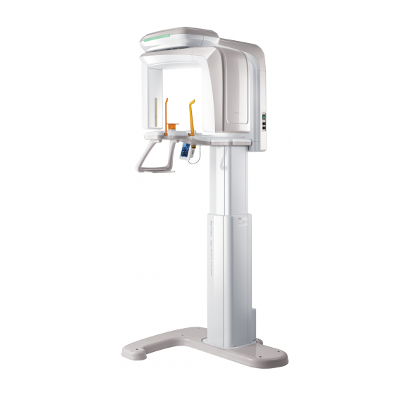
Both the PaX-Primo i includes a high resolution 10.4” LCD touch panel for easy operation and simple image previewing. The very compact size and light weight of the PaX- Primo i family (less than a 4’... - Page 11 6. Positioning patients more accurately in a way that the operator and patient face each other, resulting in creating much less distorted images. 7. The PaX-Primo has been designed to carry out the following radiological examinations. Standard Sinus...
-
Page 12: Analytical Programs Supported
Analytical programs supported The following table summarizes the anatomical programs that PaX-Primo supports. Basic Intelligent Mode Resolution Sub-mode Resolution Sub-mode Normal Adult Narrow High High Wide Child Child Standard mode Normal Adult Narrow Normal Normal Wide Child Child Segment horizontal... -
Page 13: Imaging System Construction
First the former configuration is explained with data flow algorithm. The following figure depicts the general direct connection for configuration of the PaX-Primo along with the PC through the Ethernet network. - Page 14 Data Flow chart Please do not exit the running image capture program while saving the captured image on DB. If it is the case, then the captured image got damaged and you need to retake it again. Secondly the latter configuration is explained. 2.
-
Page 15: Entering The Specific, Capturing Mode
Data Flow chart Plugging the USB Start NO Connection Copying the data from USB Display “USB not USB inserted? plugged” message Post-processing Plug USB and event notified Saving image on DB Preparing imaging Capturing image Pre-processing & Save This configuration arises when the network between the Unit and PC is not available. The USB media plays the role of the network to deliver the image from the Unit to PC. - Page 16 Then the following main screen will be displayed 4. From the above figure, click the button in red circle and you are asked to enter the password. Enter the “vatech” in the lower cases for all.
-
Page 17: Functional Distribution Of Roles
5. The following figure will appear. And go down to the lower right corner to select your choice from three types. 6. Lastly, save the setting. Now you are ready to start off. Functional distribution of roles From the Touch pad screen(LCD) From the Imaging software of the PC Control the unit operation communicate with LCD via Ethernet... -
Page 18: General View Of The Pax-Primo I
General view of the PaX-Primo i... -
Page 19: Exposure Switch
Each functional description LED LAMP: Indicates current exposure activity (green light when not in operation, but turn into orange color while x-raying) ROTATING UNIT: moves to the proper position and turns around patient’s head during exposure. X-RAY SENSOR: used to detect a dose of X-Rays through the patient and converts it into electrical signal. -
Page 20: Replacement Parts And Positioning Accessories
Replacement parts and positioning accessories Accessory Description Normal bite Support for the edentulous TMJ support Sinus support... -
Page 21: Imaging Software Overview
PC system requirements It is mandatory to check that the PC system configuration is compatible with the PC system requirements for the PaX-Primo i. If necessary, you must update your PC system configuration. DO NOT place the PC and the peripheral equipment connected to it in the immediate vicinity of the patient in the Unit. -
Page 22: Software Overview
Software overview The following figure shows initial view of imaging software running on the PC. For operating the PaX-Primo i, primarily all the operations are carried out on the Touch pad screen. And this program runs in passive way, just displaying images acquired. - Page 23 3. Pane for the selected parameters display: Shows tube voltage, kVp and tube current, mA, set through the touch pad screen. 4. Information window: Shows various kinds of text instruction messages going on currently for imaging 5. Environmental parameters configuration: Enters the various parameter setting mode for the capturing program 6.
-
Page 24: Touch Pad Screen(Lcd) Overview
Touch pad screen(LCD) overview Below is a picture that shows and describes each unique mode in which relevant functions are selected and some parameters are configured. To make a selection on the LCD, simply touch the screen with finger on the text field or icons. 3.3.1 Main screen ①... - Page 25 PA Open: will take image of the Posterior-Anterior open view Lateral Close: will take image in a projection view from the side of patient with the mouth close PA Close: takes image of the Posterior-Anterior close view ④ Sinus mode: Select imaging mode from either PA or Lateral PA: take images from point of posterior-anterior view of sinus Lateral: take images of sinus from point of side view...
-
Page 26: Standard Mode
3.3.2 Standard Mode This mode is invoked by touching “Standard” on the main screen. From this mode, you can select one specific sub modes ① Mode information window Displays the currently selected information such as imaging mode, patient type, and X- ray setting values set at each mode. -
Page 27: Special Mode
3.3.3 Special Mode This mode is called up by touching the “Special” on the main window. ① Mode information window Displays the currently selected information such as imaging mode, patient type, and X- ray setting values set at each mode. ②... -
Page 28: Tmj Mode
3.3.4 TMJ Mode ① Mode information window Displays the currently selected information such as imaging mode, patient type, and X- ray setting values set at each mode. ② Lateral Open Produces open TMJ images in lateral view. ③ Lateral Close Produces closed TMJ images in lateral view. -
Page 29: Sinus Mode
3.3.5 Sinus mode ① Mode information window Displays the currently selected information such as imaging mode, patient type, and X- ray setting values set at each mode. ② PA mode Produces images of a posterior-anterior view of Maxillary Sinus ③ Lateral Mode Produces images of a lateral view of Maxillary Sinus ④... -
Page 30: Setting Mode
3.3.6 Setting mode Information window: shows current parameter information set by user kVp/mA adjustment: adjusts the kVp and mA ─using the up/down arrows ─to reflect various patient types on the optimal exposure. Down arrow: reduce the value Up arrow: increase value Patient gender: select the patient gender Bone density selection: select the bone density suited best... -
Page 31: Exposure Time For Each Mode
Exposure time for each mode Mode Projection Time Normal 13.5 Narrow 13.5 Standard (High) Wide 13.5 Child 11.2 Normal Narrow Standard (Normal) Wide Child Lateral Lateral Sinus 10.8 Segment Horizontal 13.5 Segment Vertical 10.2 Special Bitewing 11.6 Orthogonal 13.5 (Unit: second) -
Page 32: Chapter 4 Getting Started
Chapter 4 Getting started Starting the image viewer software Make sure that All the connections between the PaX-Primo and the PC are properly connected. The PC is turned on. To start the imaging software, follow these steps. 1. On your desktop, double-click EasyDent or Start>All Programs>EasyDent. -
Page 33: Turing On The Pax-Primo I
3. Other fields, although optional, are recommended to be filled in. 4. Once all the necessary parameters are entered, Click Add to save configurations. Turing on the PaX-Primo i Before switching on the equipment, check that installation of the unit is complete. -
Page 34: Calling The Imaging Software
2. Verify that name of the patient appears in the Touch pad screen. 3. Once the previous procedures are done, the equipment is now ready to be used for acquisition. Calling the imaging software To get access to the image capture mode, take the following steps. 1. -
Page 35: Selecting The Medium For The Image Transfer
With the PaX-Primo, the functionalities of the touch pad screen and the PC are divided in such a way that the primary function of the LCD is to control the Pax-Primo System while that of the PC is to acquire, process, and save the acquired images in DICOM format. -
Page 36: Chapter 5 Acquiring Images
Chapter 5 Acquiring images Acquiring Standard Panoramic image Before acquiring image, make sure that you have: Reset a rotating unit of equipment to starting position for new entry. Selected the patient record you have created. Accessed the main program on touch pad screen to control the equipment. Have the imaging capture software on PC. -
Page 37: Preparing And Positioning The Patient
4. Adjust “kVp/mA” finely, if necessary using Up/Down arrows. Left: kVp Right: mA 5. Touch the EXIT button to return to the main screen. It is necessary to adjust exposure parameters manually to reflect the patient’s unique features like structure of bone and its density. This is done through kVp/mA adjustment. - Page 38 Ask the patient to grip both handles on either side of the unit firmly. Ask the patient to position the feet slightly forward. Although the figure itself on the above is different from the PaX-Primo, the patient’s positioning is the exactly the same...
- Page 39 5. Adjust the height of the system using the column up/down switch until the patient’s chin is resting on the chinrest. Position the patient’s chin on the normal chin support. 6. The mid-sagittal positioning laser beam for the vertical alignment and the horizontal positioning laser beam for a Frankfurt plane alignment are activated by touching Position button on the main screen.
- Page 40 9. Have the patient smile to properly position the canine laser beam at the center of the patient’s canine tooth. Rotate the thumb wheel, located under the patient support rest, forward and backward to properly align the beam. 10. Position the head of the patient to properly align their Frankfort plane with the horizontal laser beam.
- Page 41 12. Using the temple support wheel button, adjust the temple supports to fit snugly on either side of the patient’s head. The patient’s head should be immobilized. The temple support wheel button is located at the front of the patient support rest.
-
Page 42: Preparing For Launch Of X-Ray
5.1.3 Preparing for launch of X-Ray 1. Click There are two cases of environment, depending on availability of the storage devices at the image-taking moment. USB or network connection not found The following message will be displayed You are given two choices. If Okayed it will proceed in a normal imaging steps If canceled, it returns to the initial state. - Page 43 Flow of procedure USB or Network available? OKayed Main screen 2. After completion of movement, the “Ready” button will turn red and blink. Click “Ready” button. Then the rotating unit will put in proper position to be ready to take image, with the message on display.
-
Page 44: Launching The Exposure
3. Then after all the initialization processing inside the LCD modules completed, the LCD returns to the main screen and announcement that capturing image is ready is heard. USB itself is not provided with the PaX-Primo i. Thus it is recommended that the USB with following specification be mandatory to use. - Page 45 3. You see the message “Acquiring image”. If the bridge software is installed and the Ethernet network is connected, the progressive bar and the same message can be seen (displayed) on the PC (desktop) 4. Upon completing the acquisition, the LCD module will start to preprocess the panoramic image and display the resulted image on the preview window.
-
Page 46: Post-Processing On The Pc
5.1.5 Post-processing on the PC 1. After post-processing, the capture program running on the PC will display image delivered either by the USB or by the Ethernet. 2. You are asked to save image in either Normal or Autofocus mode. Save it to your choice by clicking “OK”... - Page 47 When you click the name of the patient on the patient list of EasyDent, the image list will be reconfigured. A recently captured image appears on the thumbnail images, as shown in the figure. Double click the image to check it in detail. 3.
-
Page 48: Acquiring Tmj(Temporomandibular Joint )Image
Acquiring TMJ( )image Temporomandibular Joint Before acquiring image, make sure that you have: Reset a rotating unit of equipment to starting position for new entry. Selected the patient record you have created. Accessed the main program on touch pad screen to control the equipment. Have the imaging capture software on PC. -
Page 49: Preparing And Positioning The Patient
From there, upon clicking Confirm button, it will transform into Ready button. It is necessary to adjust exposure parameters manually to reflect the patient’s unique features like structure of bone and its density. This is done through kVp/mA adjustment. Refer to the look-up table for details in APPENDIX. 5.2.2 Preparing and positioning the patient To prepare and position the patient, follow the next steps. - Page 50 Ask the patient to grip both handles on either side of the unit firmly. Ask the patient to position feet slightly forward. Although the figure itself on the above is different from the PaX-Primo, the patient’s positioning is the exactly the same...
- Page 51 5. Adjust the height of the system using the column up/down switch until the patient’s chin is resting on the chin rest. The top of the TMJ support should be in contact with the patient’s acanthion point. 6. Ensure that the patient’s shoulders remain level and their neck is relaxed. The cervical spine should be straight and upright.
- Page 52 8. The horizontal laser beam, located at the side of the column, can be adjusted up or down to accommodate different head sizes. This is done by manually moving the horizontal laser beam lever up or down. 9. Have the patient smile to properly position the canine laser beam at the center of the patient’s canine tooth.
- Page 53 12. Using the temple support wheel button, adjust the temple supports to fit snugly on either side of the patient’s head. patient’s head should immobilized. temple support wheel button is located at the front of the patient support rest. 13. Ensure that the patient does not move during image acquisition.
-
Page 54: Preparing For Launch Of X-Ray
16. Have the patients close their lips and rest their tongue at the bottom of their mouth throughout the exposure cycle. 17. Position the head of the patient to properly align their Frankfort plane with the horizontal laser beam. For proper positioning, adjust in which way the patient’s head is tilted by adjust the unit slightly upward or downward using... -
Page 55: Post-Processing Image On The Pc
5.2.5 Post-processing image on the PC Click “OK” button to save current image. TMJ mode does not support the auto-focusing features When the acquisition is finished, the acquired image is automatically transferred to the EasyDent program. - Page 56 When you click the name of the patient on the patient list of EasyDent, the image list will be reconfigured. A recently captured image appears on the thumbnail images, as shown in the figure. Double click the image to check it in detail. 1.
-
Page 57: Acquiring Sinus Image
Acquiring Sinus image Before acquiring image, make sure that you have: Reset a rotating unit of equipment to starting position for new entry. Selected the patient record you have created. Accessed the main program on touch pad screen to control the equipment. Have the imaging capture software on PC. -
Page 58: Preparing And Positioning The Patient
It is necessary to adjust exposure parameters manually to reflect the patient’s unique features like structure of bone and its density. This is done through kVp/mA adjustment. Refer to the look-up table for details in APPENDIX. 5.3.2 Preparing and positioning the patient To prepare and position the patient, follow the next steps. - Page 59 Ask the patient to position feet slightly forward. Although the figure itself on the above is different from the PaX-Primo, the patient’s positioning is the exactly the same 5. Adjust the height of the system using the column up/down switch until the patient’s chin is resting on the sinus...
- Page 60 6. Ensure that the patient’s shoulders remain level and their neck is relaxed. The cervical spine should be straight and upright. To prevent magnifications on the left and right sides of the final image, make sure that the vertical laser beam is positioned at the center of the occipital bone.
- Page 61 9. Have the patient smile to properly position the canine laser beam at the center of the patient’s premolars tooth. Rotate the thumb wheel, located under the patient support rest, forward and backward to properly align the beam. 10. Have the patient smile to properly position the canine laser beam at the center of the patient’s premolars tooth.
- Page 62 14. Ensure that the patient’s eyes are closed. Ask the patient to remain still, swallow and place the tongue in contact with the palate and to breathe through the nose. Press and hold the exposure switch button until image acquisition is complete.
-
Page 63: Preparing For Launch Of X-Ray
5.3.3 Preparing for launch of X-Ray Go to the clause ‘5.1.3 preparing for launch of X-Ray’ to follow the same procedures. 5.3.4 Launching the exposure Go to the subchapter 5.1.5 for these procedures 5.3.5 Post-processing image on the PC Click “OK” button to save current image Sinus mode does not support the auto-focusing features. - Page 64 When the acquisition is finished, the acquired image is automatically transferred to the EasyDent program. When you click the name of the patient on the patient list of EasyDent, the image list will be reconfigured. A recently captured image appears on the thumbnail images, as shown in the figure.
-
Page 65: Acquiring Special Panoramic Image
Acquiring Special Panoramic image Before acquiring image, make sure that you have: Reset a rotating unit of equipment to starting position for new entry. Selected the patient record you have created. Accessed the main program on touch pad screen to control the equipment. Have the imaging capture software on PC. -
Page 66: Preparing And Positioning The Patient
It is necessary to adjust exposure parameters manually to reflect the patient’s unique features like structure of bone and its density. This is done through kVp/mA adjustment. Refer to the look-up table for details in APPENDIX. 5.4.2 Preparing and positioning the patient To prepare and position the patient, follow the next steps. - Page 67 Ask the patient to grip both handles on either side of the unit firmly. Ask the patient to position the feet slightly forward. Although the figure itself on the above is different from the PaX-Primo, the patient’s positioning is the exactly the same...
- Page 68 5. Adjust the height of the system using the column up/down switch until the patient’s chin is resting on the chinrest. Position the patient’s chin on the normal chin support. 6. The mid-sagittal positioning laser beam for the vertical alignment and the horizontal positioning laser beam for a Frankfurt plane alignment are activated by touching Position button on the main screen.
- Page 69 8. The mid-sagittal positioning laser beam for the vertical alignment and the horizontal positioning laser beam for a Frankfurt plane alignment are activated by touching Position button on the main screen. Have the patient bite the bite block along the grooves using their upper and lower incisors.
- Page 70 11. The horizontal laser beam, located at the side of the column, can be adjusted up or down to accommodate different head sizes. This is done by manually moving the horizontal laser beam lever up or down. 12. Using the temple support wheel button, adjust the temple supports to fit snugly on either side of the patient’s head.
-
Page 71: Preparing For Launch Of X-Ray
15. Ensure that the patient’s eyes are closed. Ask the patient to remain still, swallow and place the tongue in contact with the palate and to breathe through the nose. Press and hold the exposure switch button until image acquisition is complete. 5.4.3 Preparing for launch of X-Ray Go to the clause ‘5.1.3 preparing for launch of X-Ray’... - Page 72 When the acquisition is finished, the acquired image is automatically transferred to the EasyDent program. When you click the name of the patient on the patient list of EasyDent, the image list will be reconfigured. A recently captured image appears on the thumbnail images, as shown in the figure.
-
Page 73: Sample Images Of Special Mode
5.4.6 Sample images of Special mode <Segment Horizontal> <Segment Vertical>... - Page 74 <Bitewing> <Orthogonal>...
-
Page 75: Chapter 6 Upgrading To The Imaging System With Auto-Focusing Capability
(patients), thus leading to the acquisition of much improved image free from the patient’s faulty position and arch shape. This is made possible by the VATECH’s proprietary AUTO FOCUSING (Adaptive layer mode panoramic tomography) algorithm. -
Page 76: How The Auto Focusing(Af) Mode Works
These would lead to the inferior images The auto-focusing technology comes into play In other words, the AUTO FOCUSING, which is incorporated into design of the PaX-Primo i’ s intelligence model to produce optimal digital diagnostic images, is outstanding in its performances. -
Page 77: Graphical Explanation
6.2.2 Graphical explanation 1. Selecting an optimal layer from multiple images in each region 2. Reconstructing image intelligently... -
Page 78: Typical Example
6.2.3 Typical example Reconstructed image... -
Page 79: Comparisons Between Standard And Auto Focusing Imaging
6.2.4 Comparisons between standard and AUTO FOCUSING imaging Case 1: Front teeth view is contracted Circumstance: Bite block inserted too deep into the mouth At the standard (disabled AUTO FOCUSING) AUTO FOCUSING enabled... - Page 80 Case 2: Front teeth view is enlarged locally Circumstance: the patient is positioned off the correct position At the standard (disabled AUTO FOCUSING) Viewed as being enlarged locally AUTO FOCUSING enabled Viewed as being optimized...
- Page 81 Case 3: View from the right and left sides has the different magnification Circumstance: the patient accidentally turned neck right or left At the standard (disabled AUTO FOCUSING) AUTO FOCUSING enabled...
-
Page 82: Chapter 7 Maintenance
Chapter 7 Maintenance Storage and transportation Ambient temperature: -20℃ ~ 50℃ Relative humidity: 10%~ 90% Ambient, atmospheric pressure: 500~1060 hPa Although it can be allowed to be stored up to 10 degree of slope, it is recommended that equipment be used and stored on flat, even surface. Sterilization and disinfection Sterilization and disinfection should be performed thoroughly for the items like handle frame, chin rest and bite block among other things, with which patients’... -
Page 83: General Notes
Confirm voltage frequency and power consumption meet the requirement specified on the equipment. Make sure that the equipment is well grounded. General Notes 7.5.1 Preoperational stage 1. Check the very basic things like switch contact and polarity and cable conditions are met with requirement. -
Page 84: Daily Maintenance Tasks
Daily maintenance tasks Accessories Maintenance tasks Panoramic bite block Sterilize with cold sterilization or autoclave up to134 degree before the next patient is X-rayed Temple support Sterilize the head support and chin rest with medical-grade 76% alcohol disinfectant before next patient is X-rayed Chin rest(panoramic, sinus Sterilize the head support and chin rest with medical-grade and TMJ) -
Page 85: Chapter 8 Technical Specifications
Chapter 8 Technical specifications Unit technical specifications 8.1.1 General information X-ray beam: Fan Beam Reconstruction Algorithm: A real time reconstructing algorithm Dynamic Range: 14 bit Scan Time (sec) at normal: 9.7 sec (typical). (2~13.5 sec.) Rotating Unit Scan Angle (degree): Actual rotating angle around the object X-ray Exposure Angle (degree): Actual spanning angle to expose the object to X-Ray: In fact the instant that the rotating... -
Page 86: X-Ray Generator
8.1.2 X-ray Generator continuous type High frequency generator, constant potential, micro processor controlled Ripple < 4% Inverter frequency 36 kHz push-pull Tube type D-051, stationary anode type Nominal power below than 1.3 KW Tube voltage 50 – 80 kV (adjustable by 1 kV) Tube current 2 –... -
Page 87: Dimension Of Beam Limiting Device: Collimator
8.1.5 Dimension of beam limiting device: collimator 8.1.6 Environmental Characteristics Operating temperature 10 ~ 30℃ Operating relative humidity 30 ~ 75% Operating atmospheric pressure 700 ~ 1060 hPa Transport and storage temperature -20 ~ 70℃ Transport and storage relative humidity <... -
Page 88: Dimension Of The Unit
8.1.7 Dimension of the Unit (Unit: mm) The height, 2200mm, represents the maximally allowed length using extensible (adjustable) column. -
Page 89: Focal Spot Distance
8.1.8 Focal spot distance... -
Page 90: X-Ray Generator Technical Specifications
X-Ray generator technical specifications 8.2.1 X-Ray Tube Specification D-051 Tube voltage: 50 ~ 100 kV Tube current: 1 ~ 22 mA Focal spot: 0.5 mm Inherent filtration: 0.8 mm Al Added filtration: 2.0 mm Al Total filtration: 2.8 mm Al Filament characteristics: 3.5~4.9V 3.5A(max. -
Page 91: High Voltage Generator
8.2.2 High voltage generator Tube voltage: 50 to 80kV constant potential Tube current: 2 to 10 mA direct current 8.2.3 X-Ray generation controller Focal spot length to Sensor: 678 mm Exposure time: 20sec. Cooling: 1 min. cooling time X-Ray generation limit: 50 to 90 kV and 2 to 10 mA 8.2.4 Beam limiter and its dismantled view... -
Page 92: Classification
Classification Classification according to the degree of protection against ingress of water as detailed in the current edition of IEC 529… IPXO Secondary collimator at CEPH to reduce scattered radiation According to the mode of operation: Continuous operation with intermittent loading Standards This product is designed and produced to meet the following standards: EN 60601-1, EN 60601-1-3, EN 60601-2-7, EN 60601-2-28, EN 60601-2-32,... -
Page 93: Chapter 9 Service
Service To guarantee the user and patient safety and ensure image quality this unit must be checked on regular, periodic bases by a qualified person from the VATECH. Please refer to the service manual for complete servicing information. Chapter 10... -
Page 94: Chapter 11 Emergency Measures
Chapter 11 Emergency Measures If a problem occurs while operating the product, do take the very basic emergency measures by consulting the following tables. If problem persists, please request support through the customer support information service at point of contact appeared on the back of this manual. ●... -
Page 95: Chapter 12 Recommended X-Ray Exposure Table
Chapter 12 Recommended X-Ray Exposure Table 12.1 Pano Standard Gender/Figure Hard Normal Soft 72 kVp, 8 mA 70 kVp, 8 mA 68 kVp, 8 mA Woman 70 kVp, 8 mA 68 kVp, 8 mA 66 kVp, 8 mA Child 66 kVp, 7 mA 66 kVp, 7 mA 66 kVp, 7 mA 12.2 Pano Special... - Page 96 Copyright by © 2009 Vatech The information in this document is subject to change without notice and does not represent a commitment on the part of the vendor, who assumes neither liability nor responsibility for any errors that may appear in this manual.
Need help?
Do you have a question about the PaX-Primo and is the answer not in the manual?
Questions and answers