Vatech EzRay Air VEX-P300 User Manual
Hide thumbs
Also See for EzRay Air VEX-P300:
- User manual (104 pages) ,
- User manual (296 pages) ,
- User manual (665 pages)

Related Manuals for Vatech EzRay Air VEX-P300


Summary of Contents for Vatech EzRay Air VEX-P300
- Page 1 User Manual Model : VEX-P300 Version : 1.30 English For the United Kingdom region Postal Code: 18449 13, Samsung 1-ro 2-gil, Hwaseong-si, Gyeonggi-do, Korea www.vatech.co.kr...
- Page 5 The actual equipment may differ. Due to continuous technological improvements, the manual may not contain the most updated information. For further information not covered in this manual, please contact us at: VATECH Co., Ltd. Phone: (+82) 1588 9510 E-mail: gcs@vatech.co.kr This document is originally written in English.
- Page 6 Notice This page intentionally left blank. EzRay Air (Model: VEX-P300) User Manual...
-
Page 7: Table Of Contents
Table of Contents Table of Contents Notice ......................... v Table of Contents ..................... vii General and Regulatory Information........... 1 Manufacturer's Liability ..............1 Owner and Operator's Obligations ............ 1 Conventions Used in this Manual ............2 Marks and Symbols ................. 3 Standards and Regulations .............. -
Page 8: Table Of Contents
Table of Contents Mechanical Specifications .............. 68 Technical Specifications ..............69 Electrical Specifications ..............74 Environmental Specifications ............74 Appendix ................... 76 Tables of Exposure Times (Default) ..........76 10.1 X-ray Dose Data ................77 10.2 Electromagnetic Compatibility (EMC) Information ......87 10.3 Abbreviations ................ -
Page 9: General And Regulatory Information
▪ Always use genuine VATECH approved equipment and parts. ▪ Perform all maintenance and repairs at a VATECH authorized distributor. ▪ Using this equipment properly according to the user manual. ▪ The equipment damage or malfunction is not the result of an error on the part of the owner or operator. -
Page 10: Conventions Used In This Manual
1. General and Regulatory Information Conventions Used in this Manual The following symbols are used throughout this manual. Make sure that fully understand each symbol and follow the instructions which accompany it. To prevent personal injury and/or damage to the equipment, please observe all warnings and safety information included in this document. -
Page 11: Marks And Symbols
1. General and Regulatory Information Marks and Symbols The following table describes the purpose and location of safety symbols and other important information provided on the equipment. Mark/Symbol Description Location Battery Alternate current Charger Label Direct current Main Label Attention: Main Label Consult accompanying documents Power board,... - Page 12 1. General and Regulatory Information Mark/Symbol Description Location Caution: Federal law restricts this device to Main Label sale by or about a licensed healthcare practitioner. Main Label, Manufacturer’s name and address Generator Label Main Label, Date of manufacture Generator Label This symbol indicates that electrical and electronic equipment must not be disposed Main Label...
- Page 13 1. General and Regulatory Information Label Locations 1.4.1 Generator Label Main Label EzRay Air (Model: VEX-P300) User Manual...
- Page 14 1. General and Regulatory Information UDI Label The labels in this manual are only for illustration purposes. Actual labels may differ. EzRay Air (Model: VEX-P300) User Manual...
-
Page 15: Standards And Regulations
1. General and Regulatory Information Standards and Regulations Standards: The VEX-P300 is designed and manufactured to meet the following standards: ▪ IEC/EN 60601-1, IEC/EN 60601-1-2, IEC/EN 60601-1-3, IEC/EN 60601-2-65 ▪ X-RAY EQUIPMENT for DENTAL INTRA-ORAL RADIOGRAPHY VEX-P300 IEC 60601-2-65:2012 ▪ CAN/CSA-C22.2 No. - Page 16 1. General and Regulatory Information This page intentionally left blank. EzRay Air (Model: VEX-P300) User Manual...
-
Page 17: Safety Instructions
2. Safety Instructions Safety Instructions General Safety Guidelines This equipment is designed and manufactured to ensure the greatest safety of operation. Operate and maintain it in strict compliance with the safety precautions and operating instructions contained in this manual. This equipment must be operated only by legally qualified persons. -
Page 18: Warnings And Safety Instructions
2. Safety Instructions Warnings and Safety Instructions This X-ray unit may be dangerous to patient and operator unless safe exposure factors, operating instructions, and maintenance schedules are observed. It is important to read this user manual carefully and strictly abide by all warnings and cautions stated within it. - Page 19 Make sure to use the battery only provided or approved by VATECH. If non-standard or damaged batteries are used, there is a risk of fire and explosion. Make sure to use the battery charger only provided or approved by ...
- Page 20 Contact your Service Representative for battery replacement. - DO NOT charge a fully discharged battery, as this may cause fire or explosion. Be sure to replace the battery (provided by VATECH). Batteries can be replaced by users. When charging the battery, the exposure function is locked.
-
Page 21: System Overview
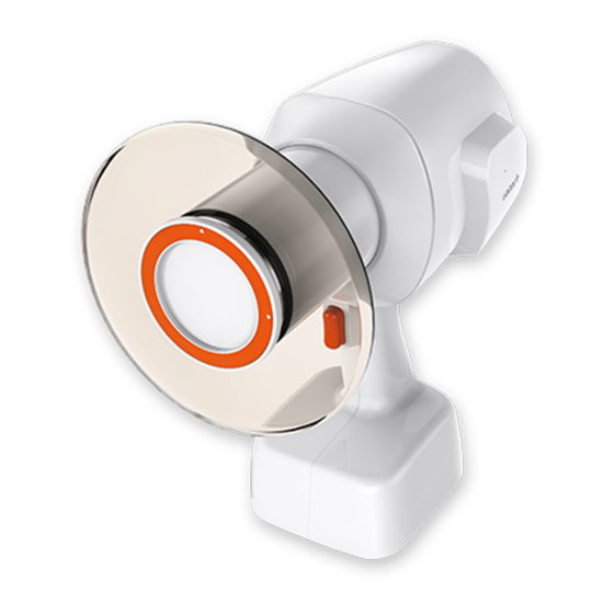
3. System Overview System Overview The VEX-P300, a portable dental X-ray system, operates on 22.2 V d.c. supplied by a rechargeable Li-ion polymer battery pack. The portable X-ray system is an X-ray generating device which is mainly designed for dental examination (teeth and jaw). The portable X-ray system is composed of an X-ray generating part with an X-ray tube including a device controller, a power controller, a user interface, a beam limiting part, a backscatter shield, and an optional Remote Exposure Switch. -
Page 22: Components
3. System Overview Components Item Standard Option Qty. VEX-P300 Main Body ● Battery Charger (power cord ● included) User Manual ● Backscatter Shield ● Round Cover ● Cradle ● Rectangular Cover (2x3) ● Rectangular Cover (4x3) ● Remote Exposure Switch ●... -
Page 23: General View Of The Equipment
3. System Overview General View of the Equipment Main Body Item Description Backscatter Shield Shields from the backscattering radiation. Limits the X-ray exposure area. X-ray Beam Limiting Default type: Round Cone + Round Cover (FOV: Ø 6 Device X-ray Exposure Press the button for X-ray exposure. - Page 24 3. System Overview Item Description Includes the X-ray tube and the high-voltage X-ray Generator generator. EzRay Air (Model: VEX-P300) User Manual...
- Page 25 3. System Overview Control Panel Item Description Tube Indicates the tube voltage and tube Voltage/Current current of the system. Indicator Angle/Time Displays the X-ray exposure time, error Display code, cooling time and exposure angle. Adult/Child Indicates a patient type (adult or child). Selection Remaining Battery...
- Page 26 3. System Overview Item Description X-ray Exposure Indicates the X-ray exposure status. Indicator (Green: Ready / Yellow: X-ray On) Turn the jog dial left (-) or right (+) to select an X-ray exposure setting, press Jog Dial the jog dial to confirm the operating setting.
-
Page 27: Operation
4. Operation Operation Power On/Off Turn on the system referring to the following figure. The following displays and indicators light up: ▪ Current Angle/Time display ▪ Tooth type selection display ▪ Adult/Child selection display ▪ Remaining battery indicator ▪ X-ray exposure indicator Make sure that at least one battery indicator light comes on. - Page 28 4. Operation When the battery indicator has one flickering light, charge the battery immediately by using the battery charger. For more information, refer to ‘4.5 Remote Exposure Switch The Remote Exposure Switch allows the operator to control image acquisition from outside of the X-ray room.
-
Page 29: Operation Mode
4. Operation Operation Mode This system can be operated in Manual Mode. Manual Mode When the tooth type selection area flickers, turn the jog dial to select the tooth type. To see the Control Panel before and after selection, refer to the figures below. - Page 30 4. Operation After tooth type selection, a patient type should be selected. When the Adult/Child selection area flickers, turn the jog dial to select the patient type. To see the Control Panel after selection, refer to the figure below. After patient type selection Patient Type Symbol Type...
-
Page 31: Positioning
4. Operation Positioning Positioning the Patient To obtain high-quality intra-oral radiography with maximum details, take extra care in all steps of the radiography process: positioning the patient and the X-ray imaging system; exposing the intra-oral sensor. Place a protective lead apron on the patient’s chest. Have the patient sit on the chair with the sagittal plane vertical. - Page 32 4. Operation Place the tube head cone in the area want to take an image. When holding the device, it is recommended to grip the handle by one hand and place the other on the underside of the Exposure Button and the cone as shown in the following figure.
- Page 33 4. Operation Positioning Instructions Paralleling technique: The sensor is placed in a holder which is used to align the sensor parallel to the long axis of the teeth. 1. Sensor 2. Long axis of the tooth Bisected angle technique: The patient holds the sensor in place with his/her finger. The X-ray beam is directed perpendicularly towards an imaginary line, which bisects the angle between the sensor plane and the long axis of the tooth.
- Page 34 4. Operation Here are the specific angulations and directions for the tube head in order to take the best images of a particular tooth (i.e. Bisected angle technique). Position the receptor carefully not to damage the soft tissue of the patient’s intra-oral area.
- Page 35 4. Operation ▪ Mandibular Incisor The x-ray beam is directed upward at 25°. Teeth Angle of inclination Incisor Mandible -25˚ EzRay Air (Model: VEX-P300) User Manual...
- Page 36 4. Operation ▪ Maxillary Canine The x-ray beam is directed downward at 45°. Teeth Angle of inclination Canine Maxilla +45˚ EzRay Air (Model: VEX-P300) User Manual...
- Page 37 4. Operation ▪ Mandibular Canine The x-ray beam is directed upward at 20°. Teeth Angle of inclination Canine Mandible -20˚ EzRay Air (Model: VEX-P300) User Manual...
- Page 38 4. Operation ▪ Maxillary Molar and Premolar The x-ray beam is directed downward at 30°. Teeth Angle of inclination Molar and Premolar Maxilla +30˚ EzRay Air (Model: VEX-P300) User Manual...
- Page 39 4. Operation ▪ Mandibular Molar and Premolar The x-ray beam is directed upward at 5°. Teeth Angle of inclination Molar and Premolar Mandible -5˚ EzRay Air (Model: VEX-P300) User Manual...
- Page 40 4. Operation ▪ Bitewing For a bitewing exposure, the patient closes their teeth during exposure on the sensor holder. The x-ray beam is directed downward at 5° ~ 8°. Teeth Angle of inclination Bitewing exposure +5˚~ +8˚ EzRay Air (Model: VEX-P300) User Manual...
- Page 41 4. Operation Positioning the Imaging Sensor To ensure image quality, the digital imaging sensor must be positioned properly (for information about the proper placement of the imaging sensor, please refer to ‘Positioning Instructions’ on page 25. ▪ Failure to position the imaging sensor properly can result in errors on the radiograph, such as distorted teeth and roots, elongation, magnification, and overlapping contacts.
- Page 42 4. Operation To ensure proper alignment between the imaging sensor and the X-ray beam, it is recommended to use a PID (Position Indicating Device) as shown in the following figure. When using the PID, the exit pattern of the X-ray device should be aligned perpendicular to the target receptor as shown in the following figure.
-
Page 43: Exposure
4. Operation Exposure The operator MUST instruct the patient to refrain from moving during the entire exposure. Instruct the patient not to move. Press the Exposure Button for exposure duration. While X-ray is being exposed, ▪ The X-ray Exposure Indicator lights up and an audible sound is produced. ▪... - Page 44 4. Operation Remote Exposure Switch 4.4.1 The Remote Exposure Switch allows the operator to control image acquisition from outside of the X-ray room. Press and hold the Remote Exposure Switch until the acquisition is completed. Premature release of the Remote Exposure Switch will abort image acquisition. Pressing the Remote Exposure Switch activates the X-ray Exposure Indicator to turn yellow.
-
Page 45: Using The Battery
4. Operation Using the Battery Battery level indicator with a residual quantity is shown on the left side of the Control Panel. When the battery indicator has one flickering light (level 1), charge the battery immediately. Refer to the battery levels as shown below. - Page 46 DO NOT charge a fully discharged battery, as this may cause fire or explosion. Be sure to replace the battery (provided by VATECH). When the device is connected to the battery charger, the Battery Charging Indicator is displayed at all times except that the battery is fully discharged.
- Page 47 4. Operation Charging the Battery Connect the battery charger to the battery charger connector as shown in the following figure. When the battery charger is connected, the battery charging LED indicator light comes on. Charge the battery until all the three LED indicators are filled up. Usually, it takes about 3 hours to fully charge the battery after a complete discharge.
- Page 48 4. Operation Battery Replacement Batteries can be replaced by users. To replace the battery, contact your Service Representative to get a battery kit (including a new battery and a Torx wrench). Manpower One person, 3 minutes Tools required Torx wrench (size: T20) Removal Procedure Using a Torx wrench, unscrew the battery bay access door.
- Page 49 4. Operation Disconnect the battery cable from the device by pressing the battery cable connector as shown in the following figure. Press and disconnect the battery cable connector Battery cable connector After disconnecting the battery cable DO NOT pull excessively on the battery cable. Install the new battery in the reverse order of removal.
- Page 50 4. Operation Sleep Mode To reduce battery consumption, the Sleep Mode is started when the system is not in use for one minute. (To see how to change the default waiting time for the Sleep Mode, see ‘Waiting Time Setting for the Sleep Mode’ on page 53.) When the Sleep Mode is started, the Control Panel becomes dark as shown in the following figure (right).
- Page 51 4. Operation Power Off Mode If the system (not in use) has been turned on for 30 minutes since the Sleep Mode was started, the Power Off Mode is started. ‘Off’ is flickering on the Control Panel. When need to be notified by an alarm when the Power Off Mode is started, change the setting referring to ‘Buzzer On/Off’...
- Page 52 4. Operation Power Save Mode If the system (not in use) has been turned on for 4 hours since the Power Off Mode was started, the Power Save Mode is started. All displays are turned off on the Control Panel. To return to normal operation in the Power Save Mode, MUST turn off the system and turn it back on.
-
Page 53: Service Mode
5. Service Mode Service Mode Overview the following settings are able to check and changed. In the Service Mode, ▪ Factory Default Settings (See ‘5.3.1 Factory Default Settings’ on page 49.) ▪ Exposure Time Settings (for each patient and tooth type) (See ‘5.3.2 Exposure Time Settings (for each patient and tooth type)‘... -
Page 54: Changing System Parameters
5. Service Mode Changing System Parameters To change system parameters: Press and hold the SET button and jog dial at the same time (for about 3 seconds). EzRay Air (Model: VEX-P300) User Manual... - Page 55 5. Service Mode Enter the 3 digits numeric password using the jog dial. (default password: 000) Press the jog dial to enter the next digit then press and hold the jog dial. EzRay Air (Model: VEX-P300) User Manual...
- Page 56 5. Service Mode After entering the password is completed, the Service Mode is started as shown in the following figure. There are a total of 10 modes. To select the first mode, press AUTO button as shown on the left, then the Service Mode number n.01 is displayed on the Control Panel as shown on the right.
-
Page 57: Service Mode Menu
5. Service Mode Service Mode Menu Perform the Service Modes described in this section referring to ‘5.2 Changing System Parameters’ on page 46. Factory Default Settings 5.3.1 Perform this mode to restore the system to the factory default settings (it initializes all the parameters except for n.24). - Page 58 5. Service Mode 5.3.2 Exposure Time Settings (for each patient and tooth type) Perform each mode to set the exposure time for each patient and tooth type referring to the table below. Service Item Mode No. n.02 Adult Incisor n.03 Adult Canine n.04 Adult Molar/ Premolar...
- Page 59 5. Service Mode 5.3.3 User Default Settings (for each patient and tooth type) Perform each mode to set the default settings for a specific patient and a tooth type referring to the table below. Service Item Mode No. n.10 Adult n.11 Child n.12...
- Page 60 5. Service Mode 5.3.4 Password Mode On/Off Perform this mode to turn on/off the password mode. Service Item Mode No. n.16 Password On n.17 Password Off To turn on the password mode, Select n.16 by pressing the jog dial, then “YES” is displayed on the Control Panel.
- Page 61 5. Service Mode 5.3.5 Waiting Time Setting for the Sleep Mode Perform this mode to set up the waiting time that takes before the Sleep Mode is started. (default: 1 minute) Service Item Mode No. n.19 Waiting time setting for the Sleep Mode To change the waiting time for the Sleep Mode, Select n.19 by pressing the jog dial, then the default time “001”...
- Page 62 5. Service Mode 5.3.6 Waiting Time Setting for the Power Off Mode Perform this mode to set up the waiting time for the Power Off Mode. (default: 30 minutes) Service Item Mode No. n.20 Waiting time setting for the Power Off Mode To change the waiting time for the Power Off Mode, Select n.20 by pressing the jog dial, then the default time “030”...
- Page 63 5. Service Mode 5.3.7 Waiting Time Setting for the Power Save Mode Perform this mode to set up the waiting time for the Power Save Mode. (default: 4 hours) Service Item Mode No. n.21 Waiting time setting for the Power Save Mode To change the waiting time for the Power Save Mode, Select n.21 by pressing the jog dial, then the default time “240”...
- Page 64 5. Service Mode 5.3.8 Buzzer On/Off Perform this mode to turn On/Off the buzzer. In case of ‘buzzer On’, there are three options: battery level 1 (flickering) warning only, Power Off Mode warning only, or both. (For details about battery levels, see ‘4.4.14.5Remote Exposure Switch The Remote Exposure Switch allows the operator to control image acquisition from outside of the X-ray room.
- Page 65 5. Service Mode Using the Battery’ on page 37.) Service Item Mode No. n.22 Buzzer On/Off To change the buzzer On/Off setting, Select n.22 by pressing the jog dial, then the default setting “000” (buzzer Off) is displayed on the Control Panel as shown in the following figure (right). Turn the jog dial to select an option out of the four options as described below.
- Page 66 5. Service Mode 5.3.9 Power Off Mode On/Off Perform this mode to turn on/off the Power Off Mode. Service Item Mode No. n.23 Power Off Mode On/Off To change the Power Off Mode On/Off setting, Select n.23 by pressing the jog dial, then the default setting “001” is displayed on the Control Panel.
- Page 67 5. Service Mode 5.3.10 Password Setting Perform this mode to change the password. Service Item Mode No. n.24 Password setting To change the password, Select n.24 by pressing the jog dial, then the default password “000” is displayed on the Control Panel as shown in the following figure (right). When the first digit flashes, turn the jog dial to change the password and then save it by pressing the jog dial.
-
Page 68: Troubleshooting
6. Troubleshooting Troubleshooting In instances of abnormal operation, error messages will be displayed on the Control Panel. If a problem persists, please request assistance from the customer support information services. Alarm/Error Messages A.0X: A problem occurred, and the system performs the correction automatically. - Page 69 6. Troubleshooting Troubleshooting Problem Cause Solution The power switch is not Turn the equipment power switch turned on properly. off and turn it back on. Recheck after charging the battery Battery discharged with a charger. Equipment is not turned on. Battery cable is not Contact your Service properly connected.
-
Page 70: Cleaning And Maintenance
7. Cleaning and Maintenance Cleaning and Maintenance Cleaning Before cleaning the equipment, make sure to turn off the equipment. The equipment surfaces can be cleaned with a soft cloth damped in an alcohol- based, non-corrosive cleaning solution. If necessary, wipe off surfaces with disinfectant. -
Page 71: Maintenance
7. Cleaning and Maintenance Maintenance VATECH requires periodic constancy tests to ensure image quality and the safety of the patient and operator. Only VATECH authorized technicians can perform inspection and service of this equipment. For the technical assistance, contact VATECH service center or your local VATECH representative. - Page 72 7. Cleaning and Maintenance Maintenance Task Checklist 7.2.1 Always turn off the equipment before performing any maintenance. Tasks Period Before the operation, ensure that the equipment is clean and Daily ready for use. After using the equipment, make sure that the equipment has Daily been turned off.
- Page 73 7. Cleaning and Maintenance This page intentionally left blank. EzRay Air (Model: VEX-P300) User Manual...
-
Page 74: Disposing Of The Unit
8. Disposing of the Unit Disposing of the Unit In order to reduce environmental contamination, this equipment is designed to be as safe as possible to use and dispose of. Many components of this equipment are environment-friendly and can be recycled. All parts and components that contain hazardous materials must be disposed of in accordance with disposal regulations. - Page 75 8. Disposing of the Unit This page intentionally left blank. EzRay Air (Model: VEX-P300) User Manual...
-
Page 76: Equipment Specifications
9. Equipment Specifications Equipment Specifications Mechanical Specifications Dimensions Item Description Dimension (mm) 280(L) x 296(H) x ø 165 Main Body Weight (kg) 1.8 (± 10 %) Round Type FOV: < ø 60 X-ray Beam X-ray Beam Area (mm) Limiting Rectangular Type FOV: 20 x 30, 40 x 30 Device SSD(Source to Skin Distance) (mm) -
Page 77: Technical Specifications
Min. 1.5 mm Al Type Inverter Type Tube Voltage 55-65 kV Tube Current 1.0-3.0 mA Manufacturer VATECH Co., Ltd. Model V1-650304 (Stationary Anode type) Focal spot size 0.4 mm (IEC 60336) Anode heat contents 0.8 kJ Maximum Anode Heat 200 W... - Page 78 9. Equipment Specifications X-ray Tube Characteristics Maximum rating chart Emission characteristics EzRay Air (Model: VEX-P300) User Manual...
- Page 79 9. Equipment Specifications Heating and cooling curves of the X-ray tube Heating and cooling curves of X-ray tube housing assembly EzRay Air (Model: VEX-P300) User Manual...
- Page 80 9. Equipment Specifications Tube Dimensions [mm] EzRay Air (Model: VEX-P300) User Manual...
- Page 81 25.2 V d.c. (4.2 V d.c./Cell) Discharge Voltage 18-25.2 V d.c. Make sure to use the battery only provided or approved by VATECH. Using an unauthorized battery may result in serious injury and equipment damage. For details on using the battery, see ‘Battery Use’...
-
Page 82: Electrical Specifications
9. Equipment Specifications Electrical Specifications Item Description Tube Voltage 65 kV fixed (± 5 %) Tube Current 2.5 mA (± 10 %) Exposure Time 0.05-0.5 s (± 2 %) Rated Voltage 22.2 V d.c. The system will be available with a fixed tube voltage specification based on the user selection. - Page 83 9. Equipment Specifications This page intentionally left blank. EzRay Air (Model: VEX-P300) User Manual...
-
Page 84: Appendix
10. Appendix 10. Appendix 10.1 Tables of Exposure Times (Default) The following exposure timetables were established with a unit equipped with a cone that corresponds to a focus-to-skin distance of 200 mm (8 inches) respectively. SSD: 200 mm (8 inches) Angle of Patient Teeth... -
Page 85: X-Ray Dose Data
10. Appendix 10.2 X-ray Dose Data The X-ray dose data is extracted from the X-ray Dose Test Report for the VEX-P300. The X-ray doses of the VEX-P300 in the test report were measured in accordance with the IEC collateral standards. The VEX-P300 was designed in accordance with Part 1. General Requirements for Safety, IEC 60601-1-3. - Page 86 10. Appendix Leakage Dose 10.2.2 Scope IEC 60601-2-65 203.12.4 Requirements In the LOADING STATE, the AIR KERMA due to LEAKAGE RADIATION from X-RAY SOURCE ASSEMBLIES, 1 m from the FOCAL SPOT, average over an area of of which no principal linear dimension exceeds 20 cm, when operated at the NOMINAL X-RAY TUBE VOLTAGE under condition of LOADING corresponding to the reference LOADING conditions, shall not exceed 0.2 mGy in one hour.
- Page 87 10. Appendix Results The following exposure timetables were established with a unit equipped with a cone that corresponds to a focus-to-skin distance of 200 mm (8 inches) respectively. When the leakage doses have been measured with each cover type (default, rectangular 2x3, and rectangular 4x3), all the results have been ND (Not Detected).
- Page 88 10. Appendix The result (Vertical Plane) Default type Rectangular 2x3 Rectangular 4x3 Direction [mGy/h] [mGy/h] [mGy/h] 0° 20° 45° 65° 90° 110° 135° 155° 180° 200° 225° 245° 270° 290° 315° 335° ▪ ND: Not Detected. The detection limit is 0.00001 mGy per exposure. EzRay Air (Model: VEX-P300) User Manual...
- Page 89 10. Appendix Scattered Dose 10.2.3 Scope IEC 60601-2-65 203.13 Requirements ME EQUIPMENT shall be provided with means to optionally allow actuation of the EXPOSURE from a PROTECTED AREA after installation. Relevant instructions shall be given in the ACCOMPANYING DOCUMENTS. Results The following exposure timetables were established with a unit equipped with a cone that corresponds to a focus-to-skin distance of 200 mm (8 inches) respectively.
- Page 90 10. Appendix Result (Horizontal Plane) [μR] Direction [°] Without Shield Without Shield 315° 19.3 24.4 335° 32.7 28.5 Result (Vertical Plane) [μR] Direction [°] Without Shield With Shield 0° 42.5 55.3 20° 39.0 30.7 45° 27.5 36.3 65° 35.5 41.8 90°...
- Page 91 10. Appendix Result (Vertical Plane) [μR] Direction [°] Without Shield With Shield 270° 290° 14.6 315° 33.2 12.6 335° 63.1 32.7 EzRay Air (Model: VEX-P300) User Manual...
- Page 92 10. Appendix Method 2 PMMA Phantom aligned to 280 mm away from Focal Spot (with Position Indicating Device) Max. Exposure Condition Measure point: 1.0, 1.5, 2.0 m from PMMA Phantom Result (Horizontal Plane) [μR] Direction [°] 1.0 m 1.5 m 2.0 m 0°...
- Page 93 10. Appendix Result (Horizontal Plane) [μR] Direction [°] 1.0 m 1.5 m 2.0 m Result (Vertical Plane) [μR] Direction [°] 1.0 m 1.5 m 2.0 m 0° 33.2 20.7 20° 16.9 10.6 45° 21.8 13.6 65° 23.0 14.4 90° 40.9 25.6 10.2 110°...
- Page 94 10. Appendix Result (Vertical Plane) [μR] Direction [°] 2.0 m 1.5 m 2.0 m 315° 335° 19.6 12.2 EzRay Air (Model: VEX-P300) User Manual...
-
Page 95: Electromagnetic Compatibility (Emc) Information
10. Appendix 10.3 Electromagnetic Compatibility (EMC) Information Guidance and manufacturer’s declaration - electromagnetic emissions The VEX-P300 is intended for use in the electromagnetic environment specified below. The customer or the user of the VEX-P300 should assure that it is used in such an environment. Electromagnetic environment - Emissions test Compliance... - Page 96 10. Appendix Guidance and manufacturer’s declaration - electromagnetic immunity The VEX-P300 is intended for use in the electromagnetic environment specified below. The customer or the user of the VEX-P300 should assure that it is used in such an environment. IEC 60601 Test Compliance Electromagnetic Immunity test...
- Page 97 10. Appendix Guidance and manufacturer’s declaration - electromagnetic immunity The VEX-P300 is intended for use in the electromagnetic environment specified below. The customer or the user of the VEX-P300 should assure that it is used in such an electromagnetic environment. IEC 60601 Compliance Electromagnetic environment -...
- Page 98 10. Appendix Field strength from fixed transmitters, such as base stations for radio (cellular/cordless) telephones and land mobile radios, amateur radio, AM and FM radio broadcast and TV broadcast cannot be predicted theoretically with accuracy. To assess the electromagnetic environment due to fixed RF transmitters, an electromagnetic site survey should be considered.
-
Page 99: Abbreviations
10. Appendix 10.4 Abbreviations Acronym Name Aluminum Electromagnetic Compatibility Electrostatic Discharge Field of View International Electro technical Commission International Standards Organization Light-Emitting Diode Medical Electrical PMMA Poly Methyl Meth Acrylate Radio Frequency Source to Image receptor Distance Signal Input Part Signal Output Part Source to Skin Distance EzRay Air (Model: VEX-P300) User Manual... - Page 100 No part of this manual may be reproduced, transmitted, or transcribed without the expressed written permission of the manufacturer. VATECH and EzRay have registered trademarks in the United States and other countries, and EzRay Air is a trademark of VATECH Co., Ltd. worldwide.
Need help?
Do you have a question about the EzRay Air VEX-P300 and is the answer not in the manual?
Questions and answers