Table of Contents
Advertisement
Quick Links
Advertisement
Table of Contents

Related Manuals for Vatech PHT-30CSS


Summary of Contents for Vatech PHT-30CSS
- Page 5 The “Optional” in this manual means that the function or features are left to the customer’s or user’s choice. Review this manual thoroughly to ensure the proper installation. The vatech A9 is in steady improvement. The information contained in this manual may be subject to change without notice, justification, or notification of the persons concerned.
-
Page 6: Important Notes
DO NOT push or pull the equipment. Only VATECH-authorized technician shall install the equipment, complying with the proper procedures and regulations stated in this manual. -
Page 7: Table Of Contents
Assembling the Base and Main Units ............42 Installing the CEPH Unit (Optional) .............. 47 Installing the Wall and Column Brackets ............ 50 Fixing the Base (Optional) ................56 Connecting the Cables to the Equipment........... 60 vatech A9 (Model: PHT-30CSS) Installation Manual... -
Page 8: Table Of Contents
Setting up the Power Management Options ..........102 Turning off the User Account Control ............104 Setting Folder Exclusions with Anti-virus Software ......... 105 Installing Software Before Beginning ..................106 Software Installation Flow ................107 Installing Image Viewer Program ..............107 vatech A9 (Model:PHT-30CSS) Installation Manual... - Page 9 Installing the Warning Lamp and Door Interlock Switch ......1 Installing the Emergency Stop Switch ............4 Connecting the 3 party Exposure Switch (Optional) ........5 Checking PC BIOS Settings ................6 Installation Checklist ..................7 vatech A9 (Model: PHT-30CSS) Installation Manual...
-
Page 11: Introduction
1. Introduction Introduction Manufacturer's Liability As the manufacturer, VATECH assumes liability for the safe and reliable installation and operation of this equipment only when: Equipment installation, including software installation, was conducted by an authorized agent by this installation manual. -
Page 12: Conventions In This Manual
NOTE Using this Manual Notes to emphasize or clarify a point. Indicates a possible danger from radiation RADIATION exposure. Indicates that an item is susceptible to damage from electrostatic discharges. susceptibility vatech A9 (Model:PHT-30CSS) Installation Manual... - Page 13 DO NOT step on the base unit while installing or operating the equipment. DO NOT use an electric drill to fix or remove bolts. (Use the drill only for drilling wall and floor) vatech A9 (Model: PHT-30CSS) Installation Manual...
- Page 14 1. Introduction vatech A9 has two carrying handles, each located at the top and bottom of the equipment (see below). Always hold the handles when moving or lifting the equipment. Three installers are required to install the equipment safely. Refer to the image below for the Emergency Stop Switch’s location.
- Page 15 DO NOT connect any items or equipment to this system that are not part of the system: IEC60601-1-1 (3rd edition: 2005). Any equipment not approved by VATECH must comply with the applicable standards: IEC 60950-1 (2nd edition: 2005) for IT equipment (Ex: PC) and IEC 60601-1 (3rd edition: 2005) for medical electrical equipment.
- Page 16 Any equipment not provided by VATECH can be connected when the following standards have complied with IEC 60950-1 and IEC 60601-1 The electrical installation shall comply with local code ...
-
Page 17: Marks And Symbols
Devices 93/42/EEC as amended by 2007/47/EC as a class IIb device. UL mark No. E476672 Label Caution: Federal law restricts this device to sale by or about a Label licensed healthcare practitioner. Manufacturer’s name and address Label vatech A9 (Model: PHT-30CSS) Installation Manual... - Page 18 This indicates that this equipment is classified as a CLASS 1 LASER Label PRODUCT by IEC 60825-1 ED.2 regulations. This indicates that the user needs Label to refer to the User Manual. Date of manufacture Label Label Serial Number vatech A9 (Model:PHT-30CSS) Installation Manual...
-
Page 19: Standards And Regulations
1. Introduction Standards and Regulations Standards vatech A9 (Model: PHT-30CSS) is designed and developed to comply with the following international standards and regulations: MEDICAL - APPLIED ELECTROMAGNETIC RADIATION EQUIPMENT AS TO ELECTRICAL SHOCK, FIRE, AND MECHANICAL HAZARDS ONLY BY ANSI/AAMI ES60601-1 (2005) + AMD 1 (2012), CAN/CSA-C22.2 No. - Page 20 1. Introduction This page is intentionally left blank vatech A9 (Model:PHT-30CSS) Installation Manual...
-
Page 21: Choosing An Installation Site
Exposure Switch close to the operator so that he/she can use them simultaneously in an emergency. 1,700 / 67” <Without CEPH Unit (optional): 2,500 mm (L) x 1,700 mm (W) or wider > vatech A9 (Model: PHT-30CSS) Installation Manual... - Page 22 2. Choosing an Installation Site <With CEPH Unit (optional): 2,500 (L) x 2,500 mm (W) or wider > vatech A9 (Model:PHT-30CSS) Installation Manual...
- Page 23 2. Choosing an Installation Site <Ceiling Height: 2,700 mm (H) or higher > vatech A9 (Model: PHT-30CSS) Installation Manual...
- Page 24 2m (7’) from the source of the radiation. Maintain visible contact with the patient and a clear view of indicators such as the PC's warning lamp and imaging status. vatech A9 (Model:PHT-30CSS) Installation Manual...
-
Page 25: Specifications For Electrical Installation
The input line voltage depends on the local electrical distribution system. Allowable input voltage fluctuation requirement: ±10 %. Mode of operation: Continuous operation with intermittent loading - Needs waiting time (at least 60 times the exposure time) before the next vatech A9 (Model: PHT-30CSS) Installation Manual... - Page 26 Exposure Time (s) ± (5 % + 50 ms) according to IEC 60601-2-63. The mains resistance should not exceed 0.045 ohm at 100 V and 0.19 ohm at 240 V. This equipment should be connected to the earthed outlet. vatech A9 (Model:PHT-30CSS) Installation Manual...
-
Page 27: Environmental Specifications
Relative humidity 30 ~ 75 % Atmospheric pressure 860 ~ 1060 hPa Temperature -10 ~ 60 ℃ During Transport Relative humidity 10 ~ 75 % (non-condensing) and Storage Atmospheric pressure 860 ~ 1060 hPa vatech A9 (Model: PHT-30CSS) Installation Manual... -
Page 28: Exposure Switch Installation Options
The user operates the Exposure Switch from inside the X-ray room. Option No. 2: The user operates the Exposure Switch from outside of the X-ray room. The switch holder is mounted outside the room as well. vatech A9 (Model:PHT-30CSS) Installation Manual... - Page 29 2. Choosing an Installation Site Option No. 3: The user operates the 3rd party Exposure Switch (not provided by VATECH). In this case, go to Appendix C Connecting the 3rd party The Exposure Switch for more information. vatech A9 (Model: PHT-30CSS)
-
Page 30: Installation Versions
2. Choosing an Installation Site Installation Versions Base Stand Type (with CEPH unit) vatech A9 (Model:PHT-30CSS) Installation Manual... - Page 31 2. Choosing an Installation Site Base stand Type (without CEPH unit) vatech A9 (Model: PHT-30CSS) Installation Manual...
- Page 32 2. Choosing an Installation Site Non-Base stand Type (with CEPH unit) vatech A9 (Model:PHT-30CSS) Installation Manual...
- Page 33 2. Choosing an Installation Site Non-Base stand Type (without CEPH unit) vatech A9 (Model: PHT-30CSS) Installation Manual...
-
Page 34: Installing The Warning Lamp And Door Interlock Switch
Install the Emergency Stop Switch along with the main power cable in the central distribution panel. Install this switch so that it is within easy reach of the operator but cannot be accidentally pressed. The switch must be a fool-proof model. vatech A9 (Model:PHT-30CSS) Installation Manual... -
Page 35: Before Installing The System
Before Installing the System Before or during the installation, ensure to go over checklists from No.3 to No.6 in Appendix E. Installation Checklist. Required Tools The following tools are required to install the vatech A9. Item Figure Size 1.5 mm -10 mm Wrench Set (0.06”... - Page 36 Anti-Static Glove Knife Tape Ruler (for Wall Mount type) Marker Pen (thick tip) (for Wall Mount type) Hammer (for Wall Mount type) Multimeter Hammer Drill L = 200 mm (7.9”) (for Wall Mount type) Transport Dolly vatech A9 (Model:PHT-30CSS) Installation Manual...
-
Page 37: Checking The Shockwatch And Tiltwatch
3. Before Installing the System Checking the ShockWatch and TiltWatch VATECH carefully inspects all equipment before their shipments. However, we highly recommend the installers check the ShockWatch and TilltWatch and the packages' conditions before opening them to ensure that the equipment has not received damages during the shipping. -
Page 38: Unpacking Boxes
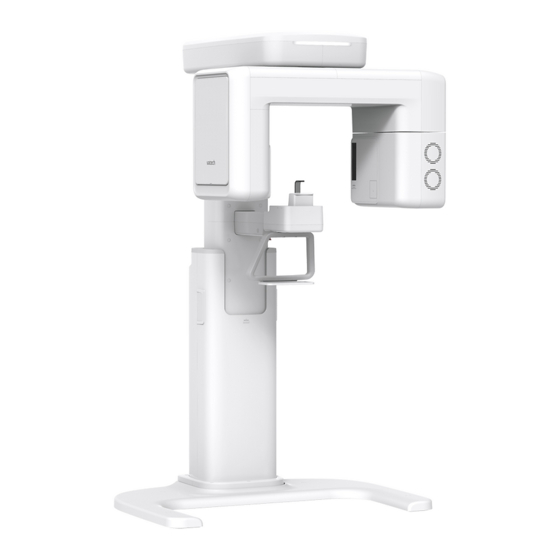
3. Before Installing the System vatech A9 (Model: PHT-30CSS) is an advanced 3 in 1 digital X-ray imaging system that incorporates PANO, CEPH (Optional), CBCT imaging capabilities into a single system. vatech A9 (Model: PHT-30CSS), a digital radiographic imaging system, acquires and processes single FOV diagnostic images for dentists. - Page 39 Main Unit While one installer is removing the side cover, another installer must be holding the box to prevent the Main Unit from falling. Remove the plastic wrap covering the box with a cutter vatech A9 (Model: PHT-30CSS) Installation Manual...
- Page 40 3. Before Installing the System Remove foams covering the Main Unit and open the accessory box, as shown in the image below. vatech A9 (Model:PHT-30CSS) Installation Manual...
- Page 41 3. Before Installing the System CEPH Box Configuration vatech A9 (Model: PHT-30CSS) Installation Manual...
- Page 42 that the center of the mass indicator is aligned with the center of the dolly. If you move the unit manually, make sure that the persons holding the upper handle take the lead. vatech A9 (Model:PHT-30CSS) Installation Manual...
- Page 43 3. Before Installing the System <Transportation Example> vatech A9 (Model: PHT-30CSS) Installation Manual...
-
Page 44: Checking The Parts
3. Before Installing the System Checking the Parts 3.4.1 Location Layout of the Parts and Accessories vatech A9 (Model:PHT-30CSS) Installation Manual... - Page 45 Yes □ No □ Sided Sticker Screws M3 x 8 Yes □ No □ Carpus Plate Yes □ No □ CEPH Option Handrest Yes □ No □ Sticker Floor Alignment Mount Yes □ No □ Plate Option vatech A9 (Model: PHT-30CSS) Installation Manual...
- Page 46 CEPH Option For Ear Rods Yes □ No □ (2: on the equipment) CEPH For Nasal Option: Silicon Cover Yes □ No □ Positioner extra Left Blank Intentionally Silicon Cap White Yes □ No □ vatech A9 (Model:PHT-30CSS) Installation Manual...
- Page 47 Yes □ No □ Washer Head M3 x 6 Yes □ No □ Screw Flat Head M4 x 8 Yes □ No □ Screw Socket Set Floor M10 x 15 Yes □ No □ Screw Mount vatech A9 (Model: PHT-30CSS) Installation Manual...
- Page 48 Yes □ No □ Bracket M8 x 25 Wrench Bolt Yes □ No □ (2 Sems) Yes □ No □ Wall Mount Silicon Yes □ No □ Wood Screw M12 x 70 For Wood Yes □ No □ vatech A9 (Model:PHT-30CSS) Installation Manual...
- Page 49 M8 x 15 w/ For Wall Wrench Bolt Spring and Flat Yes □ No □ Barcket Washers For USA Wall Bracket Yes □ No □ only countries Wall Bracket Yes □ No □ except the vatech A9 (Model: PHT-30CSS) Installation Manual...
- Page 50 3. Before Installing the System Another location Part Confirmed Items Specification Figure Comments (OK?) Base Top Yes □ No □ Cover Rear Base Top Yes □ No □ Cover Front vatech A9 (Model:PHT-30CSS) Installation Manual...
- Page 51 3. Before Installing the System Part Confirmed Items Specification Figure Comments (OK?) Column Rear Yes □ No □ Cover Column Yes □ No □ Bracket vatech A9 (Model: PHT-30CSS) Installation Manual...
-
Page 52: Installing The Equipment: Base Stand (Optional)
4.4 Fixing the base (Optional) and complete step 1 first. Then return to the 4.1 Assembling the Base and Main Unit. Remove bolts on the lower carrying handle using an Allen Wrench. Required Tool Allen Wrench 6 mm / 0.24” vatech A9 (Model:PHT-30CSS) Installation Manual... - Page 53 Required Tool Allen Wrench 6 mm / 0.24” Parts and M8 x 20 - 2 pcs Wrench Bolt Accessory (Part No. 24) Put the bolts into the holes until about 15 mm are left outside. vatech A9 (Model: PHT-30CSS) Installation Manual...
- Page 54 Hold the base unit to keep it from falling. Tighten them with an Allen Wrench to connect the Base Unit to the Column Unit. Required Tool Allen Wrench 6 mm / 0.24” vatech A9 (Model:PHT-30CSS) Installation Manual...
- Page 55 Allen Wrench to fix the Column Unit on the Base. Required Tool Allen Wrench 6 mm / 0.24” M10 x 25 Parts and w/ Spring and Flat Wrench Bolt Accessory Washers – 4 pcs (Part No. 23) vatech A9 (Model: PHT-30CSS) Installation Manual...
- Page 56 6 mm / 0.24” All four Wrench bolts, loosely tightened in steps 4 and 6, must be tightened at this step. Loosen the four bolts with an Allen Wrench and remove the part attached to the Column. vatech A9 (Model:PHT-30CSS) Installation Manual...
-
Page 57: Installing The Ceph Unit (Optional)
Open the CEPH box and take out the components. Remove the plastic wrap covering the Column Unit and the CEPH cable. Push the CEPH arm in the direction indicated below. Ensure that all four studs come through holes. vatech A9 (Model: PHT-30CSS) Installation Manual... - Page 58 Wrench Bolt (w/ C E Washer) (Part No. 25) Parts and Accessory 4 pcs C_E_Washer (Part No. 25) (If necessary) Place the Sprit level on the CEPH arm and adjust the M8 x 20 bolts. vatech A9 (Model:PHT-30CSS) Installation Manual...
- Page 59 Insert the fiber optic cable until you hear a ‘click’ sound. Assemble the Cable Cover using two bolts provided. M3 x 6 - 2 pcs Parts and Washer Head Accessory Screw (Part No. 28) vatech A9 (Model: PHT-30CSS) Installation Manual...
-
Page 60: Installing The Wall And Column Brackets
Assemble the column bracket on the back of the Column Unit using four Wrench Bolt provided. Required Tool Allen Wrench 6 mm / 0.24” M8 x 15 w/ Spring Parts and Wrench Bolt and Flat Washers Accessory - 4pc (Part No. 35) vatech A9 (Model:PHT-30CSS) Installation Manual... - Page 61 Monkey Wrench M8 x 20 w/ Spring and Flat Washers Wrench Bolt (Part No. 35) - 2 Parts and Accessory M8 - 2 pcs (Part. No. 35) DO NOT tighten the bolts fully yet. vatech A9 (Model: PHT-30CSS) Installation Manual...
- Page 62 4. Installing the Equipment: Base Stand (Optional) Marking Points on the Wall Move the equipment close to the installation site. Move the wall bracket until it touches the wall. Mark the anchor bolt locations on the wall. Required Tool Marker vatech A9 (Model:PHT-30CSS) Installation Manual...
- Page 63 M8 x 30 Parts and Flat Anchor Bolt (Part. No. 34) - 4 Accessory Using the hammer, insert an EHS tool into the inner bolt. Required Tool Hammer EAW H Parts and EHS tool Accessory 8x30 vatech A9 (Model: PHT-30CSS) Installation Manual...
- Page 64 Place the equipment on the alignment plate while observing four Hex bolts appropriately inserted through each hole. Required Tool Torque wrench Spanner type M8 x 15 Hex Bolt (Part. No. 34) Parts and Spring washer Accessory (Part. No. 34) Flat washer (Part. No. 34) vatech A9 (Model:PHT-30CSS) Installation Manual...
- Page 65 4. Installing the Equipment: Base Stand (Optional) Remove the Lower carrying handle. vatech A9 (Model: PHT-30CSS) Installation Manual...
-
Page 66: Fixing The Base (Optional)
(Part No. 34) Accessory M8 - 2 pcs Spring washer (Part No. 34) Place the Base Unit on the floor where you planned to install the equipment. And mark two locations to insert anchor bolts. (see below) vatech A9 (Model:PHT-30CSS) Installation Manual... - Page 67 Drill the floor holes of size 12 mm x 30 mm (depth) using the concrete hammer drill. Remove the debris and clean the holes using the dust pump. Remove nuts and washers, put the anchor bolts into the holes. Secure the anchor bolts with the hammer. vatech A9 (Model: PHT-30CSS) Installation Manual...
- Page 68 4. Installing the Equipment: Base Stand (Optional) Place the base unit combined equipment in the proper position, lock the nuts and washers using a ratchet wrench. vatech A9 (Model:PHT-30CSS) Installation Manual...
- Page 69 4. Installing the Equipment: Base Stand (Optional) Wooden Floor Required Tool Hammer Drill L = 200 mm (7.9”) M12 x 70 – 2 pcs Parts and Wood Screws Accessory (Part No. 34) Secure the base unit using wood screws provided. vatech A9 (Model: PHT-30CSS) Installation Manual...
-
Page 70: Connecting The Cables To The Equipment
Connect the Ethernet and other cables in the back of the Column Unit as shown in the figure. Ethernet Cable (Part No. 21) (Part No. 20) Cable Tie Parts and Accessory Exposure Switch (Part No. 2) Exposure Switch Indicator (Optional) Ethernet Cable vatech A9 (Model:PHT-30CSS) Installation Manual... - Page 71 Ensure that all cables (connected in step 1) come out of the hole located at the Column Rear Cover’s center. Use the Cable Tie (Part No. 20) to tie the cables before putting the Column Rear Cover. vatech A9 (Model: PHT-30CSS) Installation Manual...
-
Page 72: Removing The Transportation Safety Bolts
Required Tool Allen Wrench 6 mm / 0.24” Avoid damaging the cables when you are removing the safety bolts. the Safety Bolts are located inside the Vertical Frame Unite, as indicated in the image below. vatech A9 (Model:PHT-30CSS) Installation Manual... - Page 73 4. Installing the Equipment: Base Stand (Optional) Turn the Rotator Unit clockwise (DO NOT place back the Vertical Frame Cover yet.) vatech A9 (Model: PHT-30CSS) Installation Manual...
-
Page 74: Leveling The Equipment
Ensure to place the Spirit Level on the indicated locations in this manual for an accurate reading. Prepare a Spirit Level. Turn the Rotating Unit clockwise so that the X-ray tube head faces the front. Turn all nine screws in marked locations clockwise. vatech A9 (Model:PHT-30CSS) Installation Manual... - Page 75 4. Installing the Equipment: Base Stand (Optional) Leveling Right and Left Place the Spirit Level horizontally, as shown in the image. Turn Screws in marked locations left and right until the Sprit Level bubble comes to the center. vatech A9 (Model: PHT-30CSS) Installation Manual...
- Page 76 Place the Spirit Level vertically, as shown in the image. Turn Screws in marked locations left and right until the Sprit Level bubble comes to the center. When leveling the equipment is completed, ensure to tighten all eight Screws until they no longer move. vatech A9 (Model:PHT-30CSS) Installation Manual...
-
Page 77: Tightening The Bolts
4. Installing the Equipment: Base Stand (Optional) Tightening the Bolts Tighten two bolts conjoining the column and wall brackets. Allen Wrench 6 mm / 0.24” Required Tool Monkey Wrench vatech A9 (Model: PHT-30CSS) Installation Manual... - Page 78 You are advised to plan and study the installation environment carefully before proceeding since it involves drilling the wall and floor. Pre-installation planning is crucial to a successful installation. Accurate marking is of critical importance for a successful installation. Installation Overview vatech A9 (Model:PHT-30CSS) Installation Manual...
- Page 79 Put the aligning plate on the floor near the wall where you plan to install the equipment, as shown in the figure. Parts and Alignment Plate (Part No. 4) Accessory Mark 4 anchor bolts holes on the floor. Required Tool Marker vatech A9 (Model: PHT-30CSS) Installation Manual...
- Page 80 Put the anchor bolts into the holes and attach them with the hammer. Verify that the anchors are secured. Required Tool Hammer Drill L = 200 mm (7.9”) 5/16 x 60 w/ Spring and Flat Washers - Parts and Anchor Bolt 4 pcs Accessory (Part No. 34) vatech A9 (Model:PHT-30CSS) Installation Manual...
- Page 81 Grab the upper carrying handle and lift the equipment slowly until it stands on the floor, as shown in the image below. Be careful not to damage the cables before erecting the equipment. Keep them clear of the equipment. vatech A9 (Model: PHT-30CSS) Installation Manual...
- Page 82 Place the washers and nuts on Anchor Bolts. Tighten each nut loosely with a fastener. DO NOT tighten the nuts until the leveling is completed. While one installer tightens the nuts, the other installers should hold the middle handle to prevent the equipment from falling. vatech A9 (Model:PHT-30CSS) Installation Manual...
- Page 83 Please refer to section 4.3 installing the Wall and Column Brackets. Connecting the Cables to the Equipment Please refer to section 4.5 Connecting the Cables to the Equipment. Removing the Transportation Safety Bolts Please refer to section 4.6 Removing the Transportation Safety Bolts. vatech A9 (Model: PHT-30CSS) Installation Manual...
- Page 84 Ensure to place the Spirit Level s only on the following figures' locations for an accurate reading. Prepare the Spirit Level. Turn the Rotating Unit clockwise so that the X-ray tube head faces the front, as shown in the figure. vatech A9 (Model:PHT-30CSS) Installation Manual...
- Page 85 T-shaped Hex Required Tool 8 mm / 0.3” Wench M10 x 15 – 4 pcs Parts and Set Screw Accessory (Part No. 30) Place the Spirit Level, as shown in the figure. vatech A9 (Model: PHT-30CSS) Installation Manual...
- Page 86 5. Installing the Equipment: Wall Mount Place the Spirit Level on the Vertical Frame, as shown in the following figure. Tighten the nuts in the anchored bolts on the floor. vatech A9 (Model:PHT-30CSS) Installation Manual...
- Page 87 5. Installing the Equipment: Wall Mount Tightening the Bolts Tighten two bolts conjoining the Column and wall bracket. Allen Wrench 6 mm / 0.24” Required Tool Monkey Wrench Tighten the nuts in the anchored bolts. vatech A9 (Model: PHT-30CSS) Installation Manual...
-
Page 88: Completing Miscellaneous Works
(Part No. 16) Assemble the Base Top Cover Front in front of the Column Unit with 4 truss bolts and a screwdriver. (see below) Put a silicon cap (white) into each hole to complete the step. vatech A9 (Model:PHT-30CSS) Installation Manual... - Page 89 (Part No. 16) Assemble the Base Top Cover Rear in the Column Unit's back with two truss bolts and a screwdriver. (see below) Put a silicon cap (white) into each hole to complete the step. vatech A9 (Model: PHT-30CSS) Installation Manual...
-
Page 90: Assembling The Chinrest And Bite
Bite Block after acquiring a test image. Insert the normal Chinrest and the normal Bite Block into the unit. (see below) 1 pc Chinrest (Normal) (Part No. 9) Parts and Accessory 1 pc Bite (Normal) (Part No. 10) vatech A9 (Model:PHT-30CSS) Installation Manual... -
Page 91: Installing The Switch Holders
UP / DOWN Switch / Switch Holder Choose a place where you want to install a UP/DOWN Switch Holder (You can install the holder on either the left or right side of the equipment). vatech A9 (Model: PHT-30CSS) Installation Manual... - Page 92 (see below) and tighten them with a crosshead screwdriver until they no longer move. Attach a sticker on the other side of the equipment where you did not install the UP/DOWN Switch Holder Hang the UP/DOWN Switch on the holder. vatech A9 (Model:PHT-30CSS) Installation Manual...
-
Page 93: Installing The Real Miscellaneous Works
6. Completing Miscellaneous Works Installing the real miscellaneous works Tighten the Wrench Bolts connecting the CEPH Arm (see below) until they no longer move. Put a Silicon Cap on each bolt’s top. vatech A9 (Model: PHT-30CSS) Installation Manual... - Page 94 (Pan Head Screws are marked with a square, and Truss Bolts are marked with a circle.) M4 x 6 Pan Head Screw (Part No. 27) Parts and Accessory M4 x 6 Truss Bolt (Part No. 27) Put two Silicon caps on the bolt’s top connecting the Joint Bracket. vatech A9 (Model:PHT-30CSS) Installation Manual...
- Page 95 6. Completing Miscellaneous Works Insert two terminal caps on the Column Rear Cover. 2 pc Parts and Terminal Cap Accessory (Part No. 18) vatech A9 (Model: PHT-30CSS) Installation Manual...
-
Page 96: Setting Up Pc
7. Setting up PC Setting up PC Direct Connection Diagram Giga Ethernet Cable - transfers image data to the PC. Warning System Panel - provides a visible indicator: Light on when the equipment is irradiating X-ray. vatech A9 (Model:PHT-30CSS) Installation Manual... -
Page 97: The Recommended Pc Requirements
AVR (automatic voltage regulator) to keep the line voltage stable. The PC system provided with the vatech A9 undergoes a rigorous test for software compatibility before shipping. - Page 98 Click the Windows Defender Security Center icon to start Windows Defender Security Center on the search result. The start page comes with the following sections: Virus & threat protection, Device performance & health, Firewall & Network protection, Family options. vatech A9 (Model:PHT-30CSS) Installation Manual...
- Page 99 7. Setting up PC Click on the Virus & threat protection icon. Click on the link Virus & threat protection settings. vatech A9 (Model: PHT-30CSS) Installation Manual...
- Page 100 7. Setting up PC Scroll down to Exclusions. Click on the link Add or remove exclusions. vatech A9 (Model:PHT-30CSS) Installation Manual...
- Page 101 7. Setting up PC The following page will open. Click on the Add an exclusion button. 10. On the Select Folder window, type C:\VcaptureSW in the folder field and click Exclude this folder. vatech A9 (Model: PHT-30CSS) Installation Manual...
-
Page 102: Connecting The Cables To Pc
Connect the regular cables for PC: keyboard, mouse, and video in advance. Giga Ethernet 1 pc Cable (Part No. 21) Parts and Accessory 1 pc License Key (Part No. 1) Insert the 3D viewer License Key into a USB port. vatech A9 (Model:PHT-30CSS) Installation Manual... - Page 103 Check if the License Key, Video Output, and Giga Ethernet Cable are connected, as shown in the image below. Item 3D viewer License Key Video output Giga Ethernet Cable (Inserted into PCle Ethernet Card) The illustrations may differ from the actual product. vatech A9 (Model: PHT-30CSS) Installation Manual...
-
Page 104: Setting Up G-Ethernet Grabber
7. Setting up PC Setting up the G-Ethernet Grabber Entering the IP address Enter “network” on the search box. Click “View network connections” Rename the network (e.g., vatech A9). And right-click the ethernet driver and select “properties.” vatech A9 (Model:PHT-30CSS) Installation Manual... - Page 105 [Important] Select “Use the Following IP Address.” Then enter the given IP Address and Subnet Mask. (see the note below). Enter the following numbers for the IP and subnet mask. IP Address: 10.100.200.100 Subnet Mask: 255.255.255.0 Click “OK” for the next step. vatech A9 (Model: PHT-30CSS) Installation Manual...
- Page 106 7. Setting up PC Setting up the device Return to the search box and enter device manager. Select the Network adapter and right click the ethernet driver and click the Prope rties. Select the “Advanced” tab. vatech A9 (Model:PHT-30CSS) Installation Manual...
- Page 107 7. Setting up PC On the tab, scroll down until you find the “Speed & Duplex,” then click it. Click the arrow icon on the Value and select “1.0 Gpbs Full Duplex.” vatech A9 (Model: PHT-30CSS) Installation Manual...
- Page 108 7. Setting up PC [Important] Before clicking “OK,” ensure that the pop-up looks as the below vatech A9 (Model:PHT-30CSS) Installation Manual...
- Page 109 7. Setting up PC This page is intentionally left blank vatech A9 (Model: PHT-30CSS) Installation Manual...
-
Page 110: Setting Up Pc's Environment Variables
Power Options Runtime Power Management [Disable] Advanced Power Options Idle Power Savings [Normal] Advanced Power Options Enhanced Halt State (C1E) [Disable] When you update the BIOS settings, the “EnhancedHalt State (C1E)” option will be displayed. vatech A9 (Model:PHT-30CSS) Installation Manual... -
Page 111: Turning Off The Firewall
On the Windows Firewall screen, click the Turn Windows Firewall on or off. Select the Turn off Windows Firewall for both Home or work (private) and Public network location settings. Click OK to apply the settings. vatech A9 (Model: PHT-30CSS) Installation Manual... -
Page 112: Setting Up The Power Management Options
Open the Start screen, type Change screen saver in the search box. Click the Change screen saver icon to start the Screen Saver Settings on the search result. On-Screen Saver Settings screen, select (None) in the pull-down menu. Click OK to apply the settings. vatech A9 (Model:PHT-30CSS) Installation Manual... - Page 113 Click the Power Options icon to start the Power Options on the search result. Click Choose when to turn off the display. Select Never for both Turn off the display and Put the computer to sleep fields. Click Save changes to apply the settings. vatech A9 (Model: PHT-30CSS) Installation Manual...
-
Page 114: Turning Off The User Account Control
Disable the UAC by moving the slider bar down to ‘Never notify.’ Then click OK to apply change settings. You may be asked to confirm your selection or enter an administrator password. Reboot your computer for the change to take effect. vatech A9 (Model:PHT-30CSS) Installation Manual... -
Page 115: Setting Folder Exclusions With Anti-Virus Software
If you are using anti-virus software on your PC, you must exclude those files from all scans performed by the anti-virus software. For vatech A9, the following folders and files inside for relevant software should be excluded from the virus scan. -
Page 116: Installing Software
PC is the most up-to-date version. To check this, go to the website: www.nvidia.com. Perform a virus scan for the PC and InstallShield program before proceeding with its installation. vatech A9 (Model:PHT-30CSS) Installation Manual... -
Page 117: Software Installation Flow
Software Installation Flow Installing Image Viewer Program One of the image viewer programs among the EzDent-i or party program must be installed. For the details on the installation procedures, refer to the corresponding manuals. vatech A9 (Model: PHT-30CSS) Installation Manual... -
Page 118: Installing The Installshield
Insert the USB drive into the USB connector and perform a virus scan for the PC before installing the InstallShield. Go to the InstallShield folder and run Setup.exe. When the pop-up for set up appears, click Next. vatech A9 (Model:PHT-30CSS) Installation Manual... - Page 119 CEPH option. Then click Next. Confirm that the “WidePano” is selected for the CBCT sensor and click Next. Confirm that the “WidePano” is selected in the PANO sensor and click Next. vatech A9 (Model: PHT-30CSS) Installation Manual...
- Page 120 9. Installing Software (Optional) Select “WideCeph G” is for CEPH sensor type and click Next. Select the language for the equipment and click Next. vatech A9 (Model:PHT-30CSS) Installation Manual...
- Page 121 10. Select the connection for CR modality (Pano, Ceph) and click Next to continue. Select the SDK if EzDent-i has been installed. 11. Select the connection option for CBCT modality and click Next to continue. vatech A9 (Model: PHT-30CSS) Installation Manual...
- Page 122 12. Confirm that your User Option and Installation Option are selected as the image below. For the first-time installation, check all installation options provided. When the AutoSave is checked, the system saves the image data automatically. 13. Check F.Grabber-ET on the window and click NEXT. vatech A9 (Model:PHT-30CSS) Installation Manual...
- Page 123 14. On the Ready to Install window, confirm that the information you have entered is correct. If you need to make a change, click Back to return to the previous window. 15. Click Install to complete the installation when all information is confirmed. vatech A9 (Model: PHT-30CSS) Installation Manual...
- Page 124 After completing basic settings, the DICOM Viewer installation will be started. Click Next in the Welcome window. Select “I accept the terms of the license agreement” and click Next. Enter the User Name and clinic and click Next. vatech A9 (Model:PHT-30CSS) Installation Manual...
- Page 125 9. Installing Software From the next screen, click Install. Click Finish to exit the wizard. vatech A9 (Model: PHT-30CSS) Installation Manual...
- Page 126 9. Installing Software Installing the DirectX After completing the DICOM viewer installation, the DirectX® installation will be started. Select “I accept the agreement” in the Welcome window. Click Next to start the installation. vatech A9 (Model:PHT-30CSS) Installation Manual...
- Page 127 9. Installing Software Click Finish to exit the wizard. Installing fs2000 Manager Select the fs2000 manager installer from the program list. Click Next to proceed with the installation. vatech A9 (Model: PHT-30CSS) Installation Manual...
- Page 128 9. Installing Software Select the Destination Folder and click Install. Click Finish to finalize the program installation. vatech A9 (Model:PHT-30CSS) Installation Manual...
-
Page 129: Setting Up The User-Specific Information
• EzDent- i: Refer to Section 9.5.2 when the EzDent-i is installed. This program must be run in administrator mode. 9.5.1 Running the Image Viewer Run the image viewer. On your desktop, double-click the EzDent-i icon. The EzDent-i’s main window is displayed as follows. vatech A9 (Model: PHT-30CSS) Installation Manual... - Page 130 9. Installing Software 9.5.2 Interfacing the EzDent-i with Imaging Program (One-time Linking) On the main screen of the EzDent-i, click EzDent-i → Setting. Click Acquisition → Console Program. vatech A9 (Model:PHT-30CSS) Installation Manual...
- Page 131 9. Installing Software Make sure that the console program settings are as follows: Console Program Path: C:/VCaptureSW/exe/VCaptureSW.exe Capture Message: vatech A9 Captured Patient Information File Path: C:/VCaptureSW/PatientInfo.ini Click OK and restart the program to apply the settings.
- Page 132 Enter the required patient information. Chart Number, First Name, and Last Name are required fields that must be filled in. All other fields are optional, but it is recommended that they are filled in. Click Add to save the patient record. vatech A9 (Model:PHT-30CSS) Installation Manual...
- Page 133 It should disappear after the command for disabling the packing mode has been executed. For details, refer to 'Disabling the Packing Mode' on page 136. Proceed to section 9.5.5 Configuring the Parameters. vatech A9 (Model: PHT-30CSS) Installation Manual...
- Page 134 ) in the upper left corner. Log in the tap will be open by default. On the right side of the screen, select Engineer and type the password ('vatech') and then click Log In. Click on the User tab. The User Settings are displayed as shown in the following figure.
- Page 135 In the Language Option, the default language setting is English. If necessary, change the language setting from the drop-down list and click Machine Set. Click on the General Tab and type the equipment’s serial number in the Machine information. vatech A9 (Model: PHT-30CSS) Installation Manual...
- Page 136 Name as shown in the following figure. 10. In the Link Information Setting, configure the Link Type and File Extension as below. Fields When EzDent-i is used CT / CR Link Type SDK Link CR Save Name .DCM vatech A9 (Model:PHT-30CSS) Installation Manual...
- Page 137 9. Installing Software 11. Click on the Sensor / Default tab and configure the user-defined parameters. The default features can be modified according to the user’s requirement. Click Save if changes occurred. vatech A9 (Model: PHT-30CSS) Installation Manual...
- Page 138 9. Installing Software Disabling the Packing Mode vatech A9 has the Packing Mode built into the system to prevent the unit from being damaged while shipping and transporting. Since the mode is automatically turned on upon shipping, the installer must disable the Packing Mode before turning on the equipment.
- Page 139 Use the command PKEN_0001] to re-enter the packing mode. Click Exit and terminate the Control Panel. [Important] Exit the imaging program (main GUI). Reboot the system for the changes to take effect. vatech A9 (Model: PHT-30CSS) Installation Manual...
- Page 140 < When the same Music Announcement is desired for CT and PANO imaging modality > Enter the command [SPM_MPOP_0001] in the command field. < When the same Beep Announcement is desired for CT and PANO imaging modality > Enter the command [SPM_MPOP_0002] in the command field. vatech A9 (Model:PHT-30CSS) Installation Manual...
- Page 141 9. Installing Software Finalizing the Parameter Settings Click Exit → Close and terminate the Control Panel. [Important] Exit the imaging program (main GUI). vatech A9 (Model: PHT-30CSS) Installation Manual...
-
Page 142: 10. Technical Specifications
1938.9 (L) x 1314.5 (W) x 1966.0 (H) (mm) 76.4 (L) x 51.8 (W) x 77.4 (H) (inch) Base Stand/Wall Mount Installation type (Default: Wall Mount type) Main Box, CEPH Box (Optional), Base Box Packing Box Organization (Optional) vatech A9 (Model:PHT-30CSS) Installation Manual... -
Page 143: Drawing Dimensions
10. Technical Specifications 10.2 Drawing dimensions unit = mm With CEPH Without CEPH Top view (with Base) Front View (with Base) Top view (without Base) Front View (without Base) vatech A9 (Model: PHT-30CSS) Installation Manual... - Page 144 Front View 77.4 77.4 (with Base) 66.7 66.7 39.3 39.3 35.3 38.8 76.4 Top view 34.8 34.8 51.8 (without 51.8 Base) 76.4 73.8 30.4 Front View (without 76.7 Base) 76.7 61.0 61.0 38.5 34.6 38.5 vatech A9 (Model:PHT-30CSS) Installation Manual...
-
Page 145: Electrical Specifications
Allowable input voltage fluctuation requirement: ±10 %. Mode of operation: Continuous operation with intermittent loading - Needs waiting time (at least 60 times the exposure time) before the next exposure begins. vatech A9 (Model: PHT-30CSS) Installation Manual... -
Page 146: Environmental Specifications
10 ~ 35 ℃ During Operation Relative humidity 30 ~ 75 % Atmospheric pressure 860 ~ 1060 hPa Temperature -10 ~ 60 ℃ Transport and Storage Relative humidity 10 ~ 75 % Atmospheric pressure 860 ~ 1060 hPa vatech A9 (Model:PHT-30CSS) Installation Manual... - Page 147 10. Technical Specifications This page is intentionally left blank vatech A9 (Model: PHT-30CSS) Installation Manual...
-
Page 149: Vatech A9 (Model: Pht-30Css) Installation Manual
MEIGaN guideline. MEIGaN: Medical Electrical Installation Guidance Notes Pre-installation planning is crucial to the successful installation of these devices. For further details, refer to the accompanying volume: Specification for Electrical Installation Block Diagram vatech A9 (Model: PHT-30CSS) Installation Manual... - Page 150 Appendix Schematic Diagram Components Supplied vatech A9 (PHT-30CSS) Installation Manual...
- Page 151 Install the Warning System Panel at the proper height after taking each cable length into account. Connect the warning lamp (not provided). Connect the door interlock switch (not provided). Connect the power source for the warning lamp. vatech A9 (Model: PHT-30CSS) Installation Manual...
-
Page 152: Installing The Emergency Stop Switch
The cable sizes: N, L, and PE≥ 12 AWG (3 x 4 mm 2 ). The cable to Emergency Stop Switch shall be the same size as the power cable itself. Install the socket connector terminal for the 2nd protective ground wire. vatech A9 (Model: PHT-30CSS) Installation Manual... -
Page 153: Connecting The 3 Rd Party Exposure Switch (Optional)
Cut the Exposure Switch cable provided with the equipment. According to the following schematic diagram, rewire the cables. Double-check the wiring before use. Tape the end of each unused wire to prevent the wires from causing an inadvertent short circuit vatech A9 (Model: PHT-30CSS) Installation Manual... -
Page 154: Checking Pc Bios Settings
PC Model: HP Z1 PC BIOS default Main Menu Sub1 Menu Sub2 Menu Setup Value Advanced Power Options Runtime Power Management [Disable] Advanced Power Options Idle Power Savings [Normal] Power Options Enhanced Halt State (C1E) [Disable] Advanced vatech A9 (Model: PHT-30CSS) Installation Manual... -
Page 155: Installation Checklist
E. Installation Checklist 1. General Information: Customer Information about the Equipment Purchaser Name of Clinic or Hospital Address Phone E-Mail Website Dealer Information about the Equipment Seller Name of Dealer Address Phone E-Mail Website vatech A9 (Model: PHT-30CSS) Installation Manual... - Page 156 Is the freight elevator available? Is the security guard, if any, notified of the installation in advance? Are two installers, including the helpers, available to move and unload the equipment? vatech A9 (Model: PHT-30CSS) Installation Manual...
- Page 157 Did the installers take pictures of boxes before opening them? Did the installer make sure there are not any suspicious holes or scratches on the box? Is the ShockWatch indicator red? Is the TiltWatch indicator red? vatech A9 (Model: PHT-30CSS) Installation Manual...
- Page 158 Did the installer make sure the harness and equipment are well connected and not damaged? Did the installers check if the emergency button (switch) is working properly? Did the equipment be well balanced? A-10 vatech A9 (Model: PHT-30CSS) Installation Manual...
- Page 159 Type: Is the 3 party software installed? If yes, indicate the name(s) and versions. Are they compatible with software from Vatech®? If No, Version: indicate the name(s) and versions. 8. Electrical Requirements: Is the circuit breaker installed and evaluated in the distribution...
- Page 160 Is a network configured with 1 Gbit/s of CAT5? Is the equipment connected to the network? Is the network installation company identified? What is the TCP/IP address assigned? Address: What is the subnet masking address? Address: Is there a DHCP server? A-12 vatech A9 (Model: PHT-30CSS) Installation Manual...
- Page 161 No part of this manual may be reproduced, transmitted, or transcribed without the manufacturer's written permission. We reserve the right to make any alterations that may be required due to technical improvement. For the most current information, contact your VATECH representative. Tel: (+82) 1588-9510 Email: gcs@vatech.com Website: www.vatech.com...
Need help?
Do you have a question about the PHT-30CSS and is the answer not in the manual?
Questions and answers