Table of Contents
Advertisement
Quick Links
Advertisement
Table of Contents

Related Manuals for Vatech PaX-Reve3D


Summary of Contents for Vatech PaX-Reve3D
-
Page 3: Table Of Contents
Contents Chapter 1. Introduction ................. 6 1.1. System features ........................6 1.2. General view of the PaX-Reve3D ..................7 1.3. Exposure switch ........................9 Chapter 2. Preparing installation for the unit ........10 2.1. Responsibilities of the Manufacturer ................. 10 2.2. - Page 4 Image Viewer programs ..................... 47 5.5.1. 3D Image Viewer (Ez3D2009 Standard) ................ 47 5.5.2. 3D Image Viewer (Ez3D2009 Professional) ..............49 5.5.3. 3D Image Viewer (Ez3D2009 Premium) ................ 49 5.5.4. Database & File Server, 2D Image Viewer (EasyDent) ..........49 PaX-Reve3D...
- Page 5 Attention E-WOO reserves the right to change the contents of this manual if necessary for performance improvement or information complement without notification. Regarding the contents of this manual, E-WOO cannot assume liability of safe and reliable operation caused by User’s mistakes; therefore User must read this manual very carefully before using the system. The details of the system might be different from this manual according to the model.
- Page 6 Guidelines for Protection against Radiation The X-ray system may cause injury to the patients if used improperly. The instructions contained in this manual must be read and followed when operating PaX-Reve3D. The world standard regulations pertaining to radiation safety must be observed.
- Page 7 X-ray room requirement for system installation Recommended Minimum Space PaX-Reve3D 2000(W) * 2500(D) * 2500(H) mm - Above space is considered for the movement of both system operator and patient. - The system is normally installed beside a wall, and operator uses the system on left.
-
Page 8: Chapter 1. Introduction
10. Improving reliability and dependability by adopting CAN(controlled area network) protocol that generally is used in areas like airplane, thus leading to greatly reduced problem occurrences. 11. The PaX-Reve3D has been designed to carry out the following radiological examinations. Standard Panoramic mode... -
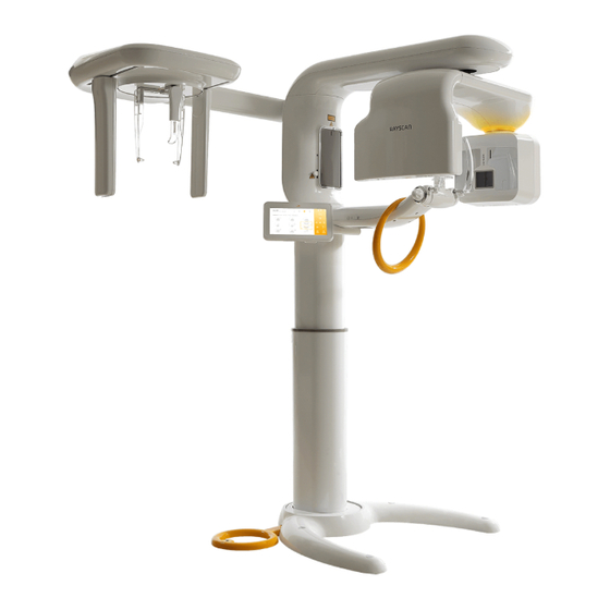
Page 9: General View Of The Pax-Reve3D
1.2. General view of the PaX-Reve3D Installation manual... - Page 10 MIRROR: let the patients correct positions by themselves through reflection in a mirror. ACCESSORY CABINET: used to keep little things relevant to the operation of this unit. TELESCOPIC COLUMN: this part of column moves up and down to be adjusted to patient height. PaX-Reve3D...
-
Page 11: Exposure Switch
STATIONARY COLUMN: this part of column is fixed to the base plate. BASE plate: used to balance and stabilize the whole equipment. 1.3. Exposure switch The exposure switch enables you to launch a radiological image acquisition via exposure button from outside the X-Ray room. -
Page 12: Chapter 2. Preparing Installation For The Unit
Internal Box Item Specification Q'TY Base Cover Base Plate Base BASE Footrest1 Footrest2 Footrest cover (Transparent) HEADREST BAND Headrest Band (Vatech) ACCESSORY CABINET Base, BITE CHIN Accessory, NORMAL CHIN SINUS CHIN NON CHIN Accessory TMJ CHIN CHIN SUPPORT With Pin (1EA) - Page 13 8 PIN LAN FOR PANO 10M LAN CABLE 8 PIN LAN FOR PANO 1M HUB CABLE HOLDER X-ray Exposure Switch Holder SPEAKER BOX SWITCH Up/Down X-ray exposure switch INDICATOR BOX Cable for exposure switch USB KEY Image reconstruction key 3D VIEWER KEY Image viewing 3D Handle table CASE...
-
Page 14: Check Shock Watch And Tilt Watch
Please check the color status of Shock Watch & Tilt Watch on each carton to see it has turned RED. If color of either of them did change, it represents great impacts in transit. Please contact your delivery company agent, or VATECH. PaX-Reve3D... -
Page 15: Chapter 3. Installing The Unit
Chapter 3. Installing the unit 3.1. Assembling the base and column Please make sure that floor surface on which the PaX-Reve3D is to be installed is flat and dry. Back Left Right Front At least 3 people are needed to carry and install this unit to prevent this product from being damaged and person from being injured. - Page 16 Procedures: 1. Carefully unpack the carton and position the unit, as follows. That is, lay the unit on the floor, with the column down, for preparing installation. 2. Please remove the moving handle using the wrench. PaX-Reve3D...
- Page 17 3. Please push the base’s rear plate (Accessory No.10) fully inside the lower part of column, as the arrows indicated below. Down Underside of lower part of column Rear bracing plate for the base 4. Please assemble the column and the base together. Be careful of the heavy weight of the unit while assembling.
- Page 18 Think about the unit is too heavy. Firmly screw 4 wrench bolts (M8*25, Accessory No.11), as stated in the following figure. Important: one person should grasp the bar, pulling the unit toward himself, to facilitate screwing bolts. After screwing 4 wrench bolts, it is no longer necessary to do this work PaX-Reve3D...
- Page 19 6. Now remove two handle bars from the unit. 7. By factory default, to prevent the unit from being damaged while shipping and moving the unit, the rotating unit and vertical frame are firmly fixed to a particular position, using wrench bolts. Please unscrew 4 screws to release those units.
- Page 20 8. Please connect the power supply and Up/Down switch cables. UP/DOWN Power supply 9. Turn on the unit and move up the column unit by approximately 20cm, using the Up/Down switch. PaX-Reve3D...
- Page 21 20cm 10. Now it is time to work on fastening the frontal part of assembly of column and base. Two procedural works are required to fix column and base together with 6 wrench bolts screws (M8*25 – Wrench bolt, 8Φ – Flat washer & spring washer] (Accessory No.14), as shown in the first figure.
- Page 22 ② Next pull it down through the hole and match the end of it onto the hole on the base. (Figure 3) ③ Do this procedure again for the other one. (Figure 4) ④ Finally turn to make them tight, using the spanner. Figure 1 Guide Shaft Assembly Figure 2 Base PaX-Reve3D...
- Page 23 Figure 3 Figure 4 12. Please cover the open area - where work has just been done, with the base cover in a way that two magnets face down on the base. Magnets Installation manual...
-
Page 24: Installing The Cephalometric Unit
① Insert the supplied Guide Shaft Assembly into the column and move it up fully so that one end of it falls in the hole. (Figure 2) ② Locate the Cephalometric unit. ③ Move it to the column unit as close as possible. ④ Locate A, B on each part, respectively and try to match them together. PaX-Reve3D... - Page 25 2. Please take out the wires, ONE72A, ONE74A and ONE75A, from the Cephalometric unit through the guide hole on the vertical frame unit when A and B are close enough each other. But leave wire ONE73A out from this work, which will be connected to the LAN Hub later. ONE72A, ONE74A and ONE75A are concerned with connection this time 3.
- Page 26 5. Please install the Case Column Top Assembly (Accessory No.05) onto the front side of column. Magnets PaX-Reve3D...
-
Page 27: Installing The Touch Pad Screen
3.3. Installing the touch pad screen 1. First push and full cables from the Touch panel screen through the wire guide hole, as indicated in red circle. The touch pad screen is supplied with Accessory No. 09. 2. Then attach the touch pad screen onto the column and fix it, using 4 screws (M4*25 truss: Accessory No.19). -
Page 28: Installing The Accessory Cabinet
Wiring installation 1. Connecting wires to the connector panel on the back of column. Please connect the RS-232, X-Ray exposure switch cable, Up/Down switch and LAN cables to the connector panel on the back of column. PaX-Reve3D... - Page 29 2. Connecting the wires from the Cephalometric unit to various components. Connect these various cables─ONE72A, ONE75A, ONE74A and ONE54A to each corresponding component, according to the following diagram. Always be careful not to plug forcefully. ONE72A UP/DOWN ONE75A ONE49A UP/DOWN ONE74A 3.
- Page 30 LAN HUB 4. Connecting the touch pad screen wires to those from the column. For these works always be careful to not force too much when plugging each other. Double check before wiring together and follow the schematic diagram. PaX-Reve3D...
- Page 31 5. Please cover the vertical frame with the Case Vertical Top, using 6 truss bolts. (M4*8: Accessory No. 6. Next fasten the Case column power (Accessory No. 06) using 4 truss bolts (M4*8: Accessory No.20). (Figure 1) And fix the Column Back Case cover (Accessory No. 02) to column. (Figure 2) Figure 1 Figure 2 7.
-
Page 32: Balancing The Equipment
2. Place the level on the side top edge of the vertical frame. While observing the level, adjust 4 bolts shown in the circles until balancing is obtained. 3. Cover those 6 holes with the supplied rubber hole caps (Accessory No.21). PaX-Reve3D... -
Page 33: Chapter 4. Installing The Control Box
Chapter 4. Installing the control box 1. 3 components for the LCD panel and its control box assembly. LCD panel (optional) control box exposure switch 2. Installing control box with the basic configuration. ① Locate the place where control box is to be mounted and fix the wall-mounted type bracket using kal block and tapping crews. - Page 34 ③ Each connector description. Power s/w: turns on/off power to control box A: is a 6-pin connector used to connect control box to the PaX-Reve3D B: is a 6-pin connector to provide the interoperability of this unit and other equipments, making X-ray exposure possible with single control box.
- Page 35 ④ Combine the control box with bracket that has already been installed on the wall. And screw them with 4 truss bolts. (M4*10) ⑤ Works have just finished. Installation manual...
- Page 36 ① Locate the place where control box is to be mounted and screw wall-mounted type bracket, using kal block and tapping crews. (M4*10) ② Match the corresponding holes of the control box and the rear bracket and assemble them, using truss bolts. (M4*10) PaX-Reve3D...
- Page 37 ③ Each connector description Power s/w: turns on/off power to control box. A: is a 6-pin connector used to connect control box to the PaX-Reve3D. B: is a 6-pin connector to provide the interoperability of this unit and other equipments, making X-ray exposure possible with single control box.
- Page 38 ⑤ Combine the control box with bracket that has already been installed on the wall. And screw them with 4 truss bolts. (M4*10) ⑥ Works have just finished. PaX-Reve3D...
-
Page 39: Chapter 5. Technical Specifications
Chapter 5. Technical specifications 5.1. Unit technical specifications 5.1.1. General information 1. General X-ray beam: Cone Beam Reconstruction Algorithm: A real time reconstructing algorithm CT reconstruction algorithm: Fast reconstruction algorithm GPU based type new MAR algorithm Dynamic Range: 14 bit Multi-FOV: (cm) Special Mode 15X15... -
Page 40: Electrical Characteristics
10 ~ 30℃ Operating relative humidity 30 ~ 75% Operating atmospheric pressure 700 ~ 1060 hPa Transport and storage temperature 20 ~ 70℃ Transport and storage relative humidity < 90% non-condensing Transport and storage atmospheric pressure 500 ~ 1060 hPa PaX-Reve3D... -
Page 41: Dimension Of Beam Limiting Device
5.1.4. Dimension of beam limiting device Installation manual... -
Page 42: Dimension Of The Unit
5.1.5. Dimension of the Unit (Unit: mm) PaX-Reve3D... -
Page 43: Focal Spot Distance
5.1.6. Focal spot distance FOD, ODD, FDD (mm) Mode (Focal Spot to Object (Object to Detector (Focal Spot to Detector Distance) Distance) Distance) 424.3 254.5 678.8 PANO 456.6 149.2 605.8 CEPH 1539.4 204.5 1743.9 Installation manual... -
Page 44: Standards
This product is designed and produced to meet the following standards: EN 60601-1, EN 60601-1-3, EN 60601-2-7, EN 60601-2-28, EN 60601-2-32, EN 60601-1-2, EN 61000-3-2, EN 61000-3-3 EN ISO 9001, EN ISO 13485 5.1.8. Marks & Graphic symbols TYPE B Equipment Radiation hazard PaX-Reve3D... -
Page 45: X-Ray Generator Specifications
5.2. X-Ray generator specifications 5.2.1. X-Ray Tube Specification (D-051) Tube voltage: 50 ~ 100 kV Tube current: 1 ~ 22 mA Focal spot: 0.5 mm Inherent filtration: 0.8 mm Al Added filtration: 2.0 mm Al Total filtration: 2.8 mm Al Filament characteristics: 3.5~4.9V 3.5A(max. -
Page 46: High Voltage Generator
13.5 sec / 12.0 sec Hemi-Panoramic (Left and Right) 6.8 sec Frontal Dentition 10.6 sec TMJ Open/Close mouth 11.2 sec (4 * 2.8 sec) Maxillary Sinus 11.0 sec <Cephalometric Examination Programs (One Shot Type)> 0.4 sec ~ 1.0 sec PaX-Reve3D... -
Page 47: Image Acquisition System
5.3. Image Acquisition system 5.3.1. Image Reconstruction time Recon time Reconstruction time Voxel Size Scan time Mode (sec) (Metal function) High (24 sec) 0.25*0.25*0.25 Normal (15sec) (150X15 High (24 sec) 0.3*0.3*0.3 Normal (15sec) High (24 sec) 0.2*0.2*0.2 Normal (15sec) (120X80) High (24 sec) It takes twice the time 0.3*0.3*0.3... -
Page 48: Panoramic Image Detector
6 mm * 148 mm Limiting Resolution 5 lp/mm Gray scale 14 bit 5.3.4. Cephalometric Image Detector Technology FPD based on a-Si TFT Pixel size 127㎛ Active area 325.1 mm * 264.2 mm Pixel resolution 3.94 lp/mm Gray scale 14 bit PaX-Reve3D... -
Page 49: Standard Accessories
5.4. Standard Accessories Chin support Temple clamps X-ray exposure switch with extensible cable Hand grips Disposable bag Bite blocks with supporters Accessory trays 5.5. Image Viewer programs 5.5.1. 3D Image Viewer (Ez3D2009 Standard) EZ3D2009 Standard is three-dimensional dental image viewer for prompt and accurate diagnosis with many useful functions as “various MPR function”, “two-dimensional analysis”... - Page 50 Capture: Pane, Region, Full screen Print CINE player Task <MPR> Rotating axis: Move, rotate, adjust thickness Oblique slice <Curve> Cross-sectional Fine tuning Opacity adjusting function 3D Zoom Implant Simulation Canal Drawing EzReport DICOM Print STL Export Memory Export (3D Basic) PaX-Reve3D...
-
Page 51: Image Viewer (Ez3D2009 Professional)
5.5.2. 3D Image Viewer (Ez3D2009 Professional) EZ3D2009 Professional supports following value-added functionality with all functionality at EZ3D2009 Standard. Dynamic Detail View CD Export-2D, 3D(Pro) Volume Measure 5.5.3. 3D Image Viewer (Ez3D2009 Premium) EZ3D2009 Premium supports following value-added functionality with all functionality at EZ3D2009 Professional. - Page 52 <Draw Tool> Free Draw Line Poly-Line <Measure Tool> Distance Continuous Distance Angle <Image Processing> Invert Sharpen Film Effect <Tool(Image Analysis)> Magnifier Slide Profile <Implant Simulation> Add Implant Add Implant Crown <Various View Mode> PaX-Reve3D...
- Page 53 If you do not properly set the device setting, causing the device to malfunction or fail, we cannot guarantee any responsibility. VATECH +82-31-379-9635 +82-31-377-9198 Email gcs@vatech.co.kr...
- Page 56 PaX-Reve3D...
Need help?
Do you have a question about the PaX-Reve3D and is the answer not in the manual?
Questions and answers