Table of Contents
Advertisement
Quick Links
KOLVER S.r.l. declares that the new tool here described : control unit model EDU 2AE is in conformity with
the following standards and other normative documents:
2006/42/CE, LVD 2014/35/UE, EMCD 2014/30/UE, EN 62841-2-2:2014, EN 62841-1: 2015, EN 60204-1,
EN 61000-6-2, EN 61000-6-4.
It is also in conformity with RoHS III normative (2011/65/UE and following 2015/863).
Name:
Position:
st
Thiene, January 1
2021
Operational Manual
EDU2AE - EDU2AE/HP
Torque range: 0.35-70 Nm
IDENTIFICATION DATA OF THE MANUFACTURER
U
VIA M. CORNER, 19/21
36016 THIENE (VI) ITALIA
IDENTIFICATION DATA OF THE PRODUCT
U
MODEL:
CODE:
TECHNICAL DATA OF THE PRODUCT
DIMENSIONS: 195 x 170 x h110 mm WEIGHT: 2,4 Kg
DECLARATION OF CONFORMITY
Giovanni Colasante
General Manager
Person authorized to compile the technical file in Kolver.
KOLVER S.r.l.
EDU 2AE
EDU2AE/HP
032000
032000/HPro
FUSE: 3.15 A
RO
RO
Giovanni Colasante
Advertisement
Table of Contents

Related Manuals for Kolver 032000


Summary of Contents for Kolver 032000
- Page 1 DIMENSIONS: 195 x 170 x h110 mm WEIGHT: 2,4 Kg DECLARATION OF CONFORMITY KOLVER S.r.l. declares that the new tool here described : control unit model EDU 2AE is in conformity with the following standards and other normative documents: 2006/42/CE, LVD 2014/35/UE, EMCD 2014/30/UE, EN 62841-2-2:2014, EN 62841-1: 2015, EN 60204-1, EN 61000-6-2, EN 61000-6-4.
- Page 2 Read the menu description carefully and in case of doubt please contact Kolver for support information. Turn the unit on through the on/off switch on the back panel. The unit will carry a general system check and “waiting connection”...
- Page 3 P L U T O 1 0 T % : 2 0 % 6 0 0 r p m 0 / 0 3 - - - r e a d y 1- Screwdriver model 2- Pre-set torque level (percentage) 3- Selected speed 4- Screw count: fastened screws/total screws (model EDU 2AE/HP only) 5- Reached torque level (model EDU 2AE/HP...
- Page 4 MENU - - - - - M A I N - M E N U - - - - - - c h a n g e E S C q u i t P r o g r a m s e t t i n g ...
- Page 5 progressively lower in order to avoid motor stalling. If the torque level is reached correctly, it will be showed on the display and you will hear a beep sound, too. Such torque level is indicated as “ T: ..% ” on the main screen. 4) TM Fast Spd (Time Fast Speed): It indicates how long the screwdriver should turn at the FAST SPEED speed (see point 6) before switching to “pre-set speed”...
- Page 6 ATTENTION: If torque isn’t reached by the maximum time, the screwdriver will stop. “Over maximum time” will be displayed on the status bar and the red led will light up. You will hear two beep sounds, too. 10) Auto Rev: This option will automatically start a reverse after a torque reached/ correct screw signal. You can set time from 0.1 to 20.0 sec.
- Page 7 Torques reached during the max torque time won’t activate the torque signal. “Error tm max torque” will be displayed and the red led will light up. You will hear two beep sounds, too. 15) Rotation: You can choose between right tightening (standard screws) or left tightening (left threaded screws).
- Page 8 automatically disappear at next screwing or when you enter the menu. Otherwise, press OK at the end of each program. ATTENTION: Every time you enter the menu, the number of screws resets to zero. Unit Options - - - - O P T I O N S - M E N U - - - - c h a n g e E S C q u i t...
- Page 9 TORQUE CALIBRATION The torque calibration function allows to view the torque value in Nm or in.lbs or kgf.cm directly on the display of the control unit. IMPORTANT: You need a torque tester to proceed, either with static transducer (model minik or K) or with rotary transducer (model minik-e).
- Page 10 6. Press OK, then the display will show: - - - - - - - - S T E P - - 1 - - - - - E n t e r t o r q u e v a l u e : 0 0 .
- Page 11 I/O CONNECTIONS EDU 2AE control unit series have connectors placed on the back panel. These connectors allow to enable functions through inputs and to take signals through outputs. The inputs are activated by connecting them to ground. A positive voltage must NEVER be brought to these inputs. Bringing 24V to the unit inputs could damage the inputs themselves.
- Page 12 Vers. 211020...
- Page 13 CN1 CONNECTOR – 10 pin: On the back panel, in all the EDU 2AE units, there is a 10 pin I/O connector. NAME FUNCTION OUTPUT +24V voltage protected. The maximum current consumption is 400mA. CAN NOT BE +24V USED TO POWER EXTERNAL DEVICES. Common pin.
- Page 14 CN2 CONNECTOR – 8 pin: Only on EDU 2AE/HP NAME FUNCTION OUTPUT Common pin for any input and output. By closing the contact between pin 1 and any of the other pins to start the function you need. This pin is connected to 0VDC and to the ground. PROGRAM It activates at the end of each program.
- Page 15 ERROR PROBLEM SOLUTION “waiting connection” doesn’t turn into “system Contact your nearest Kolver dealer. ready” after it’s been switched on. “Error Torque Control” is displayed on the status Make a new screw. If the error persists, change the torque and speed settings.
- Page 16 (400mA) exceeding the maximum load (400mA). - To reset, restart the unit. ATTENTION: IF THE OK/ESC OPTION IS DISABLED, ERRORS RESET AT THE FOLLOWING SCREWING/PROGRAM. OTHERWISE PRESS ESC. IF THE PROBLEM PERSISTS, PLEASE CONTACT YOUR NEAREST KOLVER DEALER. Vers. 211020...
- Page 17 SERIAL PORT only on EDU 2AE/HP EDU 2AE/HP control unit is supplied with a serial 9 pin male connector. In this way you can print the results of each screwing. The transmission characteristics are the following: 9600 (bits per second), 8 (data bits), n (no parity), 1 (bits stop 1). Connection pin: PIN 2 = TX, PIN 5 = GND The print string is the following: SCREWDRIVER...
- Page 18 EXPLODED VIEW EDU2AE Vers. 211020...
- Page 19 SPARE PARTS Position Description Quantity Code Screw M3x5 TX10 872444 Upper panel 2AE 819003 852521/SW Main PCB Switching 48V 600W 872490 Spacer 15mm - 4,8 mm 890004/T Washer M3 h0,5 mm 800042 Ground cable 800090/E Ferrite 872468 M3 Brass nut 800056/O Front membrane EDU 2AE 858004...
- Page 20 EXPLODED VIEW EDU2AE/HPro Vers. 211020...
- Page 21 SPARE PARTS Posizione Descrizione Quantità Codice Screw M3x5 TX10 872444 Upper panel 2AE 819003 852521/SW Main PCB Switching 48V 600W 872490 Spacer 15mm - 4,8 mm 890004/T Washer M3 h0,5 mm 800042 Ground cable 800090/E Ferrite 872468 M3 Brass nut 800056/O Front membrane EDU2AE/HPro 858009...
- Page 22 7. No one, whether an agent, servant or employee of KOLVER, is authorized to add to or modify the terms of this limited guarantee in any way. However it’s possible to extend the warranty with an extra cost.
- Page 23 DIMENSIONS: 195 x 170 x h110 mm WEIGHT: 2,4 Kg DECLARATION OF CONFORMITY KOLVER S.r.l. declares that the new tool here described : control unit model EDU 2AE/FR is in conformity with the following standards and other normative documents: 2006/42/CE, LVD 2014/35/UE, EMCD 2014/30/UE, EN 62841-2-2:2014, EN 62841-1: 2015, EN 60204-1, EN 61000-6-2, EN 61000-6-4.
- Page 24 Giovanni Colasante EDU 2AE/FR power supply and control unit is an innovative system for controlling the torque of any clutch model of PLUTO clutch series: PLUTO 3FR/HS, PLUTO 5FR and PLUTO 7FR. Of FAB series: FAB03, FAB10, FAB12 and FAB18. And of RAF series: RAF32, RAF38 and RAF50. They are available either inline, pistol, for automation and with angle head (only PLUTO).
- Page 25 Press any key on the front panel to enter the main screen (see following picture). P L U T O 5 F R 1 0 0 0 r p m S c r e w s : 0 / 0 3 a t t e s a a v v i t a t u r a 1- Screwdriver model...
- Page 26 MENU - - - - - M A I N - M E N U - - - - - - c h a n g e E S C q u i t P r o g r a m s e t t i n g U n i t o p t i o n s...
- Page 27 ATTENTION: Max Time must be set at 20.0 sec. 5) Min Time - Minimum Time: You can set this time from 0.1 sec to 'Max time - 0.1s'. To disable the function select OFF by pressing as many times as needed. (Min time = 0). Torque reached below the minimum time won’t activate the torque signal and will result in an error signal.
- Page 28 - - - - O P T I O N S - M E N U - - - - 3 ) C y c l e s : 0 0 0 0 0 0 0 0 0 4 ) C h a n g e p a s s w o r d ...
- Page 29 I/O CONNECTIONS EDU 2AE control unit series have connectors placed on the back panel. These connectors allow to enable functions through inputs and to take signals through outputs. The inputs are activated by connecting them to ground. A positive voltage must NEVER be brought to these inputs. Bringing 24V to the unit inputs could damage the inputs themselves.
- Page 30 CN1 CONNECTOR – 10 pin: On the back panel, in all the EDU 2AE units, there is a 10 pin I/O connector. Vers. 210920...
- Page 31 NAME FUNCTION OUTPUT +24V voltage protected. The maximum current consumption is 400mA. CAN NOT BE +24V USED TO POWER EXTERNAL DEVICES. Common pin. Signals must be taken between this pin (GND) and the respective signal pins. Error signal: it activates every time an error occurs. ERROR The red led on the front panel will switch on.
- Page 32 NAME FUNCTION OUTPUT Common pin for any input and output. By closing the contact between pin 1 and any of the other pins to start the function you need. PROGRAM It activates at the end of each program. Not used. INPUT RESET If pressed for at least 1 sec, it resets the program you are working in.
- Page 33 ERROR PROBLEM SOLUTION “waiting connection” doesn’t turn into “system Contact your nearest Kolver dealer. ready” after it’s been switched on. “Rev. incomplete” is displayed on the status bar (the displayed torque signal is correct but the set unscrewing is not complete).
- Page 34 SERIAL PORT only on EDU 2AE/FR: EDU 2AE/FR control unit is supplied with a serial 9 pin male connector. In this way you can print the results of each screwing. The transmission characteristics are the following: 9600 (bits per second), 8 (data bits), n (no parity), 1 (bits stop 1). Connection pin: PIN 2 = TX, PIN 5 = GND The print string is the following: SCREWDRIVER...
- Page 35 EXPLODED VIEW EDU2AE/FR Vers. 210920...
- Page 36 SPARE PARTS Position Description Quantity Code Screw M3x5 TX10 872444 Upper panel 2AE 819003 852521/SW Main PCB Switching 48V 600W 872490 Spacer 15mm - 4,8 mm 890004/T Washer M3 h0,5 mm 800042 Ground cable 800090/E Ferrite 872468 M3 Brass nut 800056/O Front membrane EDU 2AE/FR 858004...
- Page 37 7. No one, whether an agent, servant or employee of KOLVER, is authorized to add to or modify the terms of this limited guarantee in any way. However it’s possible to extend the warranty with an extra cost.
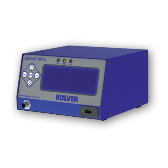
- Page 38 DIMENSIONS: 190 x 205 x h120 mm WEIGHT: 2,5 Kg DECLARATION OF CONFORMITY KOLVER S.r.l. declares that the new tool here described: control unit model EDU2AE/TOP and EDU2AE/TOP/TA is in conformity with the following standards and other normative documents: 2006/42/CE, LVD 2014/35/UE, EMCD 2014/30/UE, EN 62841-2-2:2014, EN 62841-1: 2015, EN 60204-1, EN 61000-6-2, EN 61000-6-4.
- Page 39 Read the menu description carefully and in case you are unsure please contact Kolver for support information. Turn the unit on through the on/off switch on the back panel. The unit will carry a general system check and the words “waiting connection”...
- Page 40 P L U T O 1 0 T % : 1 0 % P R : 1 0 / 0 1 r e a d y 1- Reached torque level in Nm, lbf.in or kgf.cm 2- Program number or sequence 3- Screwdriver model 4- Torque level in percentage 5- Screw count: done screws/total screws...
- Page 41 MAIN MENU: - - - - - M A I N - M E N U - - - - - - c h a n g e E S C q u i t P r o g r a m s e t t i n g ...
- Page 42 - - - - - M E N U - - P R : 1 - - - - - 3 ) M o d e l : P L U T O 1 0 4 ) R a mp : 0 .
- Page 43 7) Fast spd (Fast Speed): You can select the speed of the screwdriver during the FAST SPEED. It can be set between max speed and the Final Speed (see point 8). This function is available only if the Fast Speed Time is ON. 8) Final Spd (Final Speed): You can select any speed value of the screwdriver between nominal (maximum speed given in the catalogue) and the minimum speed of every single screwdriver (see table with...
- Page 44 14) Rev spd - Reverse speed: You can select any reverse speed value of the screwdriver between the maximum and the minimum specific speed of every single screwdriver (see table with technical data). - - - - - M E N U - - P R : 1 - - - - - 1 5 ) R e v t o r q u e : M A X...
- Page 45 - - - - - M E N U - - P R : 1 - - - - - 2 1 ) E r r o r l e v e r : 2 2 ) D e f i x a l l o w : o f f ...
- Page 46 - - - - - M E N U - - P R : 1 - - - - - 2 7 ) I n s . b a r c o d e 2 8 ) S e r i a l P R T : o f f ...
- Page 47 SEQUENCE MENU: - - - S E Q U E N C E - M E N U - - - - c h a n g e E S C q u i t 1 ) S e q s e t : 1 4 7 3 9 8 1 2 2 ) S e q u e n c e :...
- Page 48 OPTION MENU: - - - - - M A I N - M E N U - - - - - - S e q u e n c e s e t t i n g U n i t o p t i o n s ...
- Page 49 - - - - O P T I O N S - M E N U - - - - 6 ) V e r s i o n s 7 ) S e r i a l n . 0 0 0 0 0 0 0 0 ...
- Page 50 Write USB: press OK and create your new SETxx.KOL application where you save all the parameters you have set in the control unit. S a v e S E T 0 0 . K OL c o n f i r m E S C q u i t Info USB: press OK and see the loaded program.
- Page 51 4. Set the first torque level at 20% percentage by pressing (20% is just an example). - - - - - - - - S T E P - - 2 - - - - - E n t e r t h e p e r c e n t a g e 2 0 %...
- Page 52 8. Repeat the procedures described on points 4 and 5. 9. When calibration ends, “Setting end” will be displayed. You will hear two beep sounds, too. Now you are ready to work and see the correct torque on the display. WARNING: Calibration values will be referred to the parameters of the control unit which are set during calibration, i.e.
- Page 53 TORQUE/INPUT (T/IN): It corresponds to Torque mode, except for the threshold torque which can’t be set by the operator: in fact the value is the result of an external impulse through a proper contact (see paragraph “connections”). It can be very useful if the operator wants the control unit to start counting the angle from a position which is indicated by a precision instrument.
- Page 54 ANGLE/INPUT (A/IN): The threshold can’t be set by the operator: in fact the value is the result of an external impulse through a proper contact (see paragraph “connections”). This function can be very useful if the operator wants the screw to rotate a certain number of degrees after reaching a position indicated by a precision instrument.
- Page 55 I/O CONNECTIONS: EDU 2AE/TOP control unit series have connectors placed on the back panel. These connectors allow to enable functions through inputs and to take signals through outputs. The inputs are activated by connecting them to ground. A positive voltage must NEVER be brought to these inputs. Bringing 24V to the unit inputs could damage the inputs themselves.
- Page 56 Vers. 211020 Page 19...
- Page 57 CN1 CONNECTOR – 10 pins It is situated on the upper part of the back panel. NAME FUNCTION OUTPUT +24V voltage protected. The maximum current consumption is 400mA. CAN NOT BE +24V USED TO POWER EXTERNAL DEVICES. Common pin. Signals must be taken between this pin (GND and the respective signal pins (pin 3, 4 and 5).
- Page 58 CN2 CONNECTOR – 14 pins All of the following pins are input: make a contact with pin 14 to activate them. NAME FUNCTION Remote motor stop. If it’s activated the message “STOP MOTOR ON” STOP MOTOR appears on the display. The motor will stop and won’t start working again as long as the contact is closed (as Input pin 1 of CN2).
- Page 59 CN3 CONNECTOR – 11 pins All of the following pins are output. NAME FUNCTION This signal works in parallel with the green led on the front panel. GREEN LED This signal works in parallel with the red led on the front panel. RED LED This signal works in parallel with the yellow led on the front panel.
- Page 60 CN4 CONNECTOR – 9 pins All of the following pins are output. NAME FUNCTION It indicates you’re using program 1 OUTPUT 1 It indicates you’re using program 2 OUTPUT 2 It indicates you’re using program 3 OUTPUT 3 It indicates you’re using program 4 OUTPUT 4 It indicates you’re using program 5 OUTPUT 5...
- Page 61 CN5 CONNECTOR (25 pin connector - female): NAME FUNCTION Common to every input. Signals have to be enabled making contact between the desired signal and this pin (common 0VDC). Not used It indicates stop motor is enabled STOP MOTOR OUT It indicates you’re using program 8 OUTPUT 8 It indicates you’re using program 7...
- Page 62 CN7 CONNECTOR (9 pin serial connector - female) – PRINT FUNCTION NAME FUNCTION +15V Not used. Serial transmission. Serial reception. Common to every input. Signals have to be enabled making contact between the desired signal and this pin (GND). Not used.
- Page 63 ERROR PROBLEM SOLUTION “waiting connection” doesn’t turn into “loading” Contact the nearest Kolver dealer. after it’s been switched on. “Error Torque Control” is displayed on the status bar Make a new screw. If the error persists, change the torque and speed settings.
- Page 64 - Unscrewing too heavy A for at least 500 ms) ATTENTION: IF THE OK/ESC OPTION IS DISABLED, ERRORS RESET AT THE FOLLOWING SCREW/PROGRAM. OTHERWISE PRESS ESC. IF THE PROBLEM PERSISTS, PLEASE CONTACT YOUR NEAREST KOLVER DEALER. Vers. 211020 Page 27...
- Page 65 RX, PIN 5 = GND) and a mini USB connector. You can print the results of each screwing on a printer (for example Kolver model PRNTR1) and/or on PC (for example through Hyper Terminal or Realterm or any data transmission program or EDU EXPAND only on EDU2AE/TOP ver. 3.00 – only print not setting). You can also save those results on a USB device (only on EDU2AE/TOP/E and EDU2AE/TOP/TA from ver.
- Page 66 EDU EXPAND EDU EXPAND is the software for pc created by Kolver to set, change and save all parameters of EDU2AE/TOP/E or EDU2AE/TOP/TA 3.0 unit. It communicates with the control unit via miniUSB or RS232 and makes you create up to 100 different settings configurations, save them on your USB drive and then recall on your EDU unit.
- Page 67 Here is the main screen when a program has been recalled or when you are creating a new one. To modify or enter any parameter values, double click a cell, select a number within the proper range, then press Enter. If the value is not within its valid range, pressing Enter will not confirm the change.
- Page 68 Open terminal: to display the print string (see Serial Print). To save in a .txt file the results of each Open terminal: to display the print string (see Serial Print). To save in a .txt file the results of each Open terminal: to display the print string (see Serial Print).
- Page 69 EXPLODED VIEW: EDU2AE/TOP 5.00 Vers. 211020 Page 32...
- Page 70 SPARE PARTS: Position Description Quantity Code Upper panel EDU2AE/TOP 819003 3x5 Button head screw burnished TX10 872444 Motor board 852521/SW M3 toothed washer 800041 Switching 48V 600W 872490 M3 burnished nut 800056 I/O EDU 2AE/TOP board 852525 M3 brass nut 800056/O Ground cable 800090/E...
- Page 71 EXPLODED VIEW: EDU2AE/TOP/E 5.00 Vers. 211020 Page 34...
- Page 72 SPARE PARTS: Position Description Quantity Code Upper panel EDU2AE/TOP 819003 3x5 Button head screw burnished TX10 872444 Motor board 852521/SW M3 toothed washer 800041 Switching 48V 600W 872490 M3 burnished nut 800056 I/O EDU 2AE/TOP/E board 852525/E M3 brass nut 800056/O Ground cable 800090/E...
- Page 73 EXPLODED VIEW: EDU2AE/TOP/TA 5.00 Vers. 211020 Page 36...
- Page 74 SPARE PARTS: Posizione Descrizione Quantità Codice Upper panel EDU2AE/TOP 819003 3x5 Button head screw burnished TX10 872444 Motor board 852521/SW M3 toothed washer 800041 Switching 48V 600W 872490 M3 burnished nut 800056 I/O EDU 2AE/TOP/TA board 852525/TA M3 brass nut 800056/O Ground cable 800090/E...
- Page 75 7. No one, whether an agent, servant or employee of KOLVER, is authorized to add to or modify the terms of this limited guarantee in any way. However it’s possible to extend the warranty with an extra cost.
-
Page 76: Table Of Contents
TABLE OF CONTENTS Introduction and table of screwdriver models page 2 Main screen and front panel page 3 Main Menu page 4 Program Menu page 4 Program number page 4 Screws number page 4 Model page 5 Ramp page 5 Torque page 5 Time Fast Speed... - Page 77 Password page 11 ESC-OK-RESET page 11 Unit (Nm, lbf.in, kgf.cm) page 11 Versions page 12 Serial Number page 12 Set time & date page 12 Cycles page 12 USB Options page 12 Read USB page 12 Write USB page 13 Info USB page 13 Torque Calibration...
- Page 78 DIMENSIONS: 190 x 205 x h120 mm WEIGHT: 2,0 Kg DECLARATION OF CONFORMITY KOLVER S.r.l. declares that the new tool here described: control unit model EDU2AE/TOP/NT/TA is in conformity with the following standards and other normative documents: 2006/42/CE, LVD 2014/35/UE, EMCD 2014/30/UE, EN 62841-2-2:2014, EN 62841-1: 2015, EN 60204-1, EN 61000-6-2, EN 61000-6-4 It is also in conformity with RoHS III normative (2011/65/UE and following 2015/863).
- Page 79 Read the menu description carefully and in case you are unsure please contact Kolver for support information. Turn the unit on through the on/off switch on the back panel. The unit will carry a general system check and the words “waiting connection”...
-
Page 80: Main Menu
FRONT PANEL KEYBOARD To enter the menu press the ESC key for 2 seconds. Select the line by pressing then press OK (the symbol will turn into ). Press the to select the required value and then confirm through OK (or ESC if you don’t want to save the value). -
Page 81: Program Menu
- - - - - M A I N - M E N U - - - - - - S e q u e n c e s e t t i n g U n i t o p t i o n s ... -
Page 82: Runtime
ATTENTION: Reaching the torque while the ramp is still on could give as result a different torque level from the one that results when the ramp is over. This is due to the motor acceleration. Reaching the torque while the ramp is still on will activate the “screw OK” signal anyway (this option is useful if you need to tighten screws that are already tightened, the so called “double hit”... -
Page 83: Minimum Time
10) Min time - Minimum Time: You can select the minimum time of screwing from 0.1 sec to 'Max time - 0.1s'. To disable the function press until you get to OFF (Min time = 0). Torque reached below the minimum time won’t activate the torque signal and will result in an error signal. -
Page 84: Pv Torque
16) PV torque: Period of time in which the screwdriver works at maximum torque before switching to the torque that has been set by the user. You can set time from 0.1 to 10.0 sec. To disable the function press until you get to OFF. -
Page 85: Compensation
23) Compens – Compensation: This function allows an increase or decrease of the displayed torque value. The available range is from 0 to ±599.9 Ncm. For example: you make a screwing on your assembly and compare the displayed value to the value you see on a torque tester (for example a miniK/S model). Let's say you notice that the torque displayed in the unit EDU2AE/TOP/NT/TA is +2 Ncm higher than the value indicated on the tester (which is the right one). -
Page 86: Sequence Menu
30) Ang. min – Minimum angle: Minimum angle threshold. You can set it when T&A is set on Tor, T/in or T/lv (see T&A specific instructions). The minimum angle the operator can set is 5°. - - - - - M E N U - - P R : 1 - - - - - 3 0 ) A n g . -
Page 87: Sequence
ON Seq. : you can set the Sequence by scanning its barcode. The code scanned is compared with the sequence entered in the menu (see point 5: Ins. Barcode Seq on Menu Sequence). If the two codes match, the sequence set is loaded, otherwise display “Repeat scan”. The read code is also printed on the serial port of the control unit (see section Serial Print). -
Page 88: Versions
- - - - O P T I O N - - M E N U - - - - 3 ) P a s s w o r d : 4 ) E S C - O K - R S T : e x t ... -
Page 89: Usb Options
USB Options: - - - - O P T I O N S - M E N U - - - - 1 ) R e a d U S B r i t e U S B 3 ) I n f o U S B Read USB:... -
Page 90: Use Of T&A
USE OF T&A (Torque & Angle) Choose the T & A mode (see point 26: Modify function on the program menu) It is possible to set 6 different modes: TORQUE (Torque): It’s the most common use mode. The control unit shows the tightening torque and the torque starting from a certain torque percentage (threshold torque, see point 27). - Page 91 Starting from the preset threshold torque (see point 27) the system will start counting the degrees and when the preset angle is reached the screwdriver will stop. If the preset angle is reached the screw will be considered as correctly tightened, the green led will light up and the message “tightening OK”...
-
Page 92: Interpretation Of Acoustic Signales
INTERPRETATION OF ACOUSTIC SIGNALS The control unit emits sounds which help you understand if the screwing has been carried out correctly or not. When the torque is reached meeting all the parameters set, the control unit utters a 0.5 sec beep as confirmation. - Page 93 These pins can be used directly connected to PNP inputs (PLC) or used to turn on LEDs, buzzers or other devices with 24V power supply. The maximum total power of the outputs is about 400mA. Using inductive loads such as relays or other loads with an initial consumption peak greater than 400mA will send all outputs to protection, displaying the message "output disable".
- Page 94 CN1 CONNECTOR – 10 pins It is situated on the upper part of the back panel. NAME FUNCTION OUTPUT +24V voltage protected. The maximum current consumption is 400mA. CAN NOT BE +24V USED TO POWER EXTERNAL DEVICES. Common pin. Signals must be taken between this pin (GND and the respective signal pins (pin 3, 4 and 5).
- Page 95 CN2 CONNECTOR – 14 pins All of the following pins are input: make a contact with pin 14 to activate them. NAME FUNCTION Remote motor stop. If it’s activated the message “STOP MOTOR ON” STOP MOTOR appears on the display. The motor will stop and won’t start working again as long as the contact is closed (as Input pin 1 of CN2).
- Page 96 CN3 CONNECTOR – 11 pins All of the following pins are output. NAME FUNCTION This signal works in parallel with the green led on the front panel. GREEN LED This signal works in parallel with the red led on the front panel. RED LED This signal works in parallel with the yellow led on the front panel.
- Page 97 CN4 CONNECTOR – 9 pins All of the following pins are output. NAME FUNCTION It indicates you’re using program 1 OUTPUT 1 It indicates you’re using program 2 OUTPUT 2 It indicates you’re using program 3 OUTPUT 3 It indicates you’re using program 4 OUTPUT 4 It indicates you’re using program 5 OUTPUT 5...
- Page 98 CN5 CONNECTOR (25 pin connector - female): NAME FUNCTION Common to every input. Signals have to be enabled making contact between the desired signal and this pin (common 0VDC). Not used It indicates stop motor is enabled STOP MOTOR OUT It indicates you’re using program 8 OUTPUT 8 It indicates you’re using program 7...
- Page 99 CN7 CONNECTOR (9 pin serial connector - female) – PRINT FUNCTION NAME FUNCTION +15V Not used. Serial transmission. Serial reception. Common to every input. Signals have to be enabled making contact between the desired signal and this pin (GND). Not used.
-
Page 100: Trouble Shooting
ERROR PROBLEM SOLUTION “waiting connection” doesn’t turn into “loading” Contact the nearest Kolver dealer. after it’s been switched on. “Error Torque Control” is displayed on the status bar Make a new screw. If the error persists, change the torque and speed settings. - Page 101 (it happens in case of over current on mosfets) - Joint too soft ATTENTION: IF THE OK/ESC OPTION IS DISABLED, ERRORS RESET AT THE FOLLOWING SCREW/PROGRAM. OTHERWISE PRESS ESC. IF THE PROBLEM PERSISTS, PLEASE CONTACT YOUR NEAREST KOLVER DEALER. Vers. 220920...
-
Page 102: Serial Print
RX, PIN 5 = GND) and a mini USB connector. You can print the results of each screwing on a printer (for example Kolver model PRNTR1) and/or on PC (for example through Hyper Terminal or Realterm or any data transmission program or EDU EXPAND only on EDU2AE/TOP/NT/TA). You can also save those results on a USB device (only ver. - Page 103 EDU EXPAND EDU EXPAND is the software for pc created by Kolver to set, change and save all parameters of EDU2AE/TOP/NT/TA unit. It communicates with the control unit via miniUSB or RS232 and makes you create up to 100 different settings configurations, save them on your USB drive and then recall on your EDU unit.
-
Page 104: Expand
Here is the main screen when a program has been recalled or when you are creating a new one. To modify or enter any parameter values, double click a cell, select a number within the proper range, then press Enter. If the value is not within its valid range, pressing Enter will not confirm the change. - Page 105 Report of the screwing done If you connect the USB drive to the control unit, the unit creates a folder where the report of the screwing done will be saved. The folder is named as the serial number of the unit. The text file which contains all the screwing data is named as the current date.
- Page 106 EXPLODED VIEW: EDU2AE/TOP/NT/TA Vers. 220920...
- Page 107 SPARE PARTS: Posizione Descrizione Quantità Codice Upper panel EDU2AE/TOP 819003 3x5 Button head screw burnished TX10 872444 Motor board 852521/NT M3 toothed washer 800041 Switching 31,3V 872490/NT M3 burnished nut 800056 I/O EDU 2AE/TOP/TA board 852525/NT/TA M3 brass nut 800056/O Ground cable 800090/E Ferrite...
- Page 108 7. No one, whether an agent, servant or employee of KOLVER, is authorized to add to or modify the terms of this limited guarantee in any way. However it’s possible to extend the warranty with an extra cost.
- Page 109 It is also in conformity with RoHS III normative (2011/65/UE and following 2015/863). Nome/Name: Giovanni Colasante Posizione/Position: Amministratore Delegato/General Manager Persona incaricata a costituire il fascicolo tecnico presso la Sede/ Person authorized to compile the technical file in Kolver Giovanni Colasante Thiene, 1° gennaio 2021 Vers. 080920...
- Page 110 Manuale Istruzioni/ Operator’s Handbook Avvitatori/ Screwdrivers EDU1BL - EDU1BL/SG Unità di controllo/ Control units KOLVER S.r.l. VIA MARCO CORNER, 19/21 36016 THIENE (VI) ITALIA TEL +39 0445 371068 www.kolver.it Vers. 080920...
- Page 111 Modello/ Codice/ Coppia/ Output Unità di controllo/ Model Code Torque Nm min-max Control unit Diritti/ Inline KBL04FR 190004 0,04-0,4 700-1150 190015 0,4-1,5 700-1150 KBL15FR EDU1BL ¼ Hex o/or EDU1FR KBL30FR 190030 0,7-3,0 700-1150 KBL40FR 190040 0,9-4,0 400-700 Diritti - segnali/ Inline - signals KBL04FR/S 190004/S 0,04-0,4...
- Page 112 KBL../AR Modello/ Codice/ Coppia/ Output Unità di controllo/ Torque Nm min-max Model Code Control unit Diritti Auto-reverse/ Inline Auto-reverse 190004/AR 0,04-0,4 700-1150 KBL04FR/AR KBL15FR/AR 190015/AR 0,4-1,5 700-1150 EDU1BL ¼ Hex 190030/AR 0,7-3,0 700-1150 KBL30FR/AR KBL40FR/AR 190040/AR 0,9-4,0 400-700 Diritti - segnali Auto-reverse / Inline – signals Auto-reverse 190004/S/AR 0,04-0,4 700-1150...
- Page 113 1. Applicazioni Gli avvitatori elettrici KOLVER vengono utilizzati per avvitare alla coppia richiesta viti, dadi, bulloni, grani e qualunque alto organo di collegamento filettato su qualunque materiale. Tutti i modelli sono reversibili e quindi utilizzabili anche per svitare. Gli impieghi più frequenti sono nel montaggio di apparecchi elettronici in genere, elettrodomestici, cablaggi, giocattoli, lampadari, occhiali etc.
- Page 114 E’ possibile bloccare la ghiera tramite un coprifrizione (venduto separatamente). Per posizionarlo correttamente, è necessario togliere l’anello di fermo #2, svitare la ghiera di regolazione #3, svitare e togliere l’anello frontale #1 e sostituirlo con il copri frizione #35. A raggiungimento della coppia impostata, i modelli KBL…/AR invertono automaticamente il senso di rotazione fino al rilascio della leva da parte dell'operatore.
- Page 115 Modelli KBL..FR cavo 5 poli utilizzo con EDU 1FR Per tutti i modelli KBL è possibile utilizzare la centralina EDU 1FR di cui sfrutterà solo i pin necessari per alimentare l'avvitatore. Tutta la gestione del motore avviene in un'apposita scheda posizionata all'interno dell'avvitatore.
- Page 116 Dimensioni Unità di controllo Caratteristiche Peso kg 120W, 1 connettore 8 pin, velocità EDU1BL/SG regolabile. Input: segnali di partenza e 130 x 118 x 67 inversione. Output: segnali di coppia e leva. Su questo modello nel pannello posteriore è presente un connettore I/O a 10 pin. NOME FUNZIONE INPUT...
- Page 117 1. Questo prodotto è garantito da difetti di lavorazione o di materiali per un periodo massimo di 12 mesi a partire dalla data di acquisto presso KOLVER, sempre che il suo impiego sia stato limitato ad un unico turno per tutto quel periodo. Se il ritmo d’impiego supera il funzionamento di un unico turno, la durata della garanzia sarà...
- Page 118 2. Use KOLVER screwdriving system is composed by a screwdriver, a cable with 2 x M12 female 5 pin connectors and a power supply and control unit. To install it please follow the instructions. a) Connect the connectors of the cable to the controller and to the screwdriver and tighten the relevant nuts.
- Page 119 After each adjustment, it is possible to lock the nut with the clutch cover (sold separately). To place properly this cover, you must remove the stopper ring #2, unscrew the adjusting nut #3, unscrew and remove the front ring #1 and replace it with the clutch cover #35. When the pre-set torque is reached, the KBL.../AR models automatically reverse the direction of rotation until the operator releases the lever.
- Page 120 Dimensions Weight Control unit Features EDU1BL 120W, 5 pin connector, adjustable speed 130 x 118 x 67 EDU1FR 120W, 5 pin connector, adjustable speed 130 x 118 x 67 KBL..FR/S, KBL..FR/CA models – 8 pin cable – use with EDU 1BL/SG controller EDU1BL/SG is made especially to work in combination with KBL../S (either lever or push start, inline or pistol type) and KBL..CA screwdrivers.
- Page 121 Kolver suggests greasing the gears after half a million cycles. Should you have any problems or doubts, please contact the nearest Kolver technical centre. We kindly remind you to switch the control unit off when not in use.
- Page 122 7. No one, whether an agent, servant or employee of KOLVER, is authorized to add to or modify the terms of this limited guarantee in any way. However it’s possible to extend the warranty with an extra cost.
- Page 123 KBL04 – 15 – 30 – 40/FR ESPLOSO/ EXPLODED VIEW Vers. 080920...
- Page 124 PARTI DI RICAMBIO/ SPARE PARTS COD. COD. COD. COD. DESCRIZIONE/ DESCRIPTION KBL04 KBL15 KBL30 KBL40 Anello frontale/Front ring 251101 251101 251201 251401 Anello di fermo/ Nut stopper ring 251102 251102 251202 251402 Ghiera regolazione coppia/ Torque adjusting nut 251103 251103 251203 251403 Pin/ Knotting pin (3)
- Page 125 KBL04 – 15 – 30 – 40FR/CA ESPLOSO/ EXPLODED VIEW Vers. 080920...
- Page 126 PARTI DI RICAMBIO/ SPARE PARTS COD. COD. COD. COD. DESCRIZIONE/ DESCRIPTION KBL04 KBL15 KBL30 KBL40 251202 251402 Anello di fermo/ Nut stopper ring 251102 251102 251203 251403 251103 251103 Ghiera regolazione coppia/ Torque adjusting nut 251004 251004 Pin/ Knotting pin (3) 251004 251004 251205...
- Page 127 KBL04 – 15FR/CA/FN ESPLOSO/ EXPLODED VIEW PARTI DI RICAMBIO/ SPARE PARTS DESCRIZIONE/ DESCRIPTION COD. KBL04FR/CA 190004/CA KBL15FR/CA 190015/CA Compensatore/ Axial compensator 800322 Vite/ Screw M3x5 T10 (4) 801003 Flangia supporto/ Support plate 251140 Vite/ Screw M3x5 200039 Bussola guida telescopica/ Telescopic drive bush 251141 Permaglide 800334...
- Page 128 PARTI DI RICAMBIO/ SPARE PARTS DESCRIZIONE/ DESCRIPTION COD. Anello di fermo/ Nut stopper ring 251202 251203 Ghiera regolazione coppia/ Torque adjusting nut Pin/ Knotting pin (3) 251004 Corpo sede frizione/ Torque adjusting bolt 251205 Anello di fermo / Collar stopper 251006 Molla/ Collar spring 251007...
- Page 129 KBL30-40FR/CA/FN: ESPLOSO/ EXPLODED VIEW PARTI DI RICAMBIO/ SPARE PARTS DESCRIZIONE/ DESCRIPTION COD. KBL30FR/CA 190030/CA KBL40FR/CA 190040/CA Compensatore/ Axial compensator 800322 Vite/ Screw M3x5 200039 Flangia supporto/ Support plate 251240 Vite/ Screw M3x5 200039 Bussola guida telescopica/ Telescopic drive bush 251241 Permaglide 800334 Cavo/ Cable 5 pin...
- Page 130 INGOMBRI/ DRAWINGS: KBL04-15FR – KBL04-15FR/S KBL30-40FR – KBL30-40FR/S: Vers. 080920...
- Page 131 KBL04-15P KBL30-40P Vers. 080920...
- Page 132 KBL04-15FR /ANG: Vers. 080920...
- Page 133 KBL30-40FR /ANG: Vers. 080920...
- Page 134 KBL04-15FR/CA Vers. 080920...
- Page 135 KBL04-15FR/CA/FN Vers. 080920...
- Page 136 KBL30-40FR/CA: Vers. 080920...
- Page 137 KBL30-40FR/CA/FN Vers. 080920...
- Page 138 EDU 1BL : ESPLOSO / EXPLODED VIEW EDU 1BL: PARTI DI RICAMBIO/ SPART PARTS DESCRIZIONE/ DESCRIPTION COD. DESCRIZIONE/ DESCRIPTION COD. Contenitore/ Box 811010/VB Vite/ Screw M4 x 4 mm 806635 Scheda PCB/ Main board 856807/B Pannello posteriore/ Back panel 831617 Presa con portafusibile/ Socket with Pannello anteriore/ Front panel 821605...
- Page 139 EDU 1BL/SG : ESPLOSO / EXPLODED VIEW EDU 1BL/SG: PARTI DI RICAMBIO/ SPART PARTS DESCRIZIONE/ DESCRIPTION COD. DESCRIZIONE/ DESCRIPTION COD. Contenitore/ Box 811010/VB Vite/ Screw M4 x 4 mm 806635 Scheda PCB/ Main board 856807/T Pannello posteriore/ Back panel 831717/SG Presa con portafusibile/ Socket with Pannello anteriore/ Front panel 821605/SG...
- Page 140 RoHS III normative (2011/65/UE and following 2015/863). Nome/Name: Giovanni Colasante Posizione/Position: Amministratore Delegato/General Manager Persona incaricata a costituire il fascicolo tecnico presso la Sede/ Person authorized to compile the technical file in Kolver Giovanni Colasante Thiene, 1° gennaio 2021 Vers. 080920...
- Page 141 Manuale Istruzioni/ Operator’s Handbook FAB/ RAF Avvitatori/ Screwdrivers EDU1FR/ EDU1FR/SG Unità di controllo/ Control unit KOLVER S.r.l. VIA MARCO CORNER, 19/21 36016 THIENE (VI) ITALIA TEL +39 0445 371068 www.kolver.it Vers. 080920...
- Page 142 L x Coppia/ Avvio/ Start Modello/ Model Codice/ Code Torque Nm Option FAB03SS/FR 110003/FR 0,05 - 0,3 Leva/ Lever 226 x 36 FAB10RE/FR 110010/FR 0,05 - 0,8 1000 Leva/ Lever 226 x 36 110012/FR 0,2 - 1,2 1000 Leva/ Lever 226 x 36 FAB12RE/FR 112012/FR...
- Page 143 1. Applicazioni Gli avvitatori elettrici KOLVER vengono utilizzati per avvitare alla coppia richiesta viti, dadi, bulloni, grani e qualunque alto organo di collegamento filettato su qualunque materiale. Tutti i modelli sono reversibili e quindi utilizzabili anche per svitare.
- Page 144 3. Regolazione della coppia di serraggio La coppia di serraggio degli avvitatori si regola variando la tensione della molla della frizione, avvitando o svitando la ghiera filettata #2 dopo avere allentato la ghiera di bloccaggio #30. Per aumentare la coppia ruotare la ghiera in senso orario, per diminuire la coppia ruotare la ghiera in senso antiorario.
- Page 145 Il modello EDU 1FR/SG può essere utilizzato con qualsiasi avvitatore Kolver per utilizzo manuale o automatico, con frizione meccanica, sia a leva che a spinta, diritto o a pistola. Unità di Caratteristiche Dimensioni Peso controllo 120W, 1 connettore, velocità e rampa...
- Page 146 L’unità di controllo è stata progettata per non avere alcuna usura elettrica di alcun tipo. Se si dovessero tuttavia presentare dei problemi si consiglia di rivolgersi ad un tecnico KOLVER specializzato. Si raccomanda di spegnere l’unità alla fine di ogni sessione di lavoro.
- Page 147 Questo prodotto è garantito da difetti di lavorazione o di materiali per un periodo massimo di 12 mesi a partire dalla data di acquisto presso KOLVER, sempre che il suo impiego sia stato limitato ad un unico turno per tutto quel periodo. Se il ritmo d’impiego supera il funzionamento di un unico turno, la durata della garanzia sarà...
- Page 148 2. Use KOLVER screwdriving system is composed by a screwdriver, a cable with 2 x M12 female 5 pin connectors and a power supply and control unit. To install it please follow the instructions.
- Page 149 3. Adjusting the torque The torque value of the screwdriver is adjusted by changing the tension of the clutch spring, screwing or unscrewing the threaded #2 nut. After each adjustment lock the nut by means of #30 ring. To increase the torque turn the nut clockwise, to decrease it turn the nut anticlockwise.
- Page 150 EDU1FR/SG can be used with any Kolver screwdriver with clutch, either lever or push start, inline or pistol type. This model rear panel presents one connector for input and output signals. Input: start, reverse, stop motor and torque HL. Output: torque and pressed lever signals (24V 20mA).
- Page 151 Continuous use over 80% of torque range is not recommended. NOTE The sound level generated by Kolver electric screwdrivers is always lower than 70dB(A). The vibrations transmitted to operator’s hand are lower than 2.5m/s². In particular the exposition to vibrations is lower than 1m/s²...
-
Page 152: Guarantee
3. This guarantee does not cover repair or replacement required as a consequence of products which have been abused, misused or modified, or which have been repaired using not original KOLVER spare parts or by not authorized service personnel. 4. KOLVER accepts no claim for labour or other expenditure made upon defective products. - Page 153 FAB..RE/FR: ESPLOSO/ EXPLODED VIEW Vers. 080920...
- Page 154 FAB..RE/FR: PARTI DI RICAMBIO/ SPARE PARTS DESCRIZIONE/ DESCRIPTION COD. DESCRIZIONE/ DESCRIPTION COD. Anello di fermo/Stop ring 200001 Cuscinetto/ Bearing 200035 Ghiera regolazione coppia/ Torque nut 211002 Distanziale/ Spacer 200036 Sfera/ Steel ball 200003 Anello/ Circlip 200037 Anello/ Circlip 200004 Corona riduzione/ Inner gear 210038 Boccola/ Bushing 200005...
- Page 155 FAB..PS/FR: ESPLOSO/ EXPLODED VIEW Vers. 080920...
- Page 156 FAB..PS/FR: PARTI DI RICAMBIO/ SPARE PARTS DESCRIZIONE/ DESCRIPTION COD. DESCRIZIONE/ DESCRIPTION COD. Anello di fermo/Stop ring 200001 Corona riduzione/ Inner gear 210038 Ghiera regolazione coppia/ 202002 Grano fissaggio corona/ Screw 210039 Torque nut Sfera/ Steel ball 200003 Anello/ Circlip 210040 Anello/ Circlip 200004 Rondella/ Washer...
- Page 157 FAB..PP/FR: IMPUGNATURA/ HOUSING PARTI DI RICAMBIO/ SPARE PARTS DESCRIZIONE/ COD. DESCRIPTION Vite/ Screw M3 x 6 TS (2) 801002 Portamotore/ Motor cover 234507 Vite impugnatura/ Screw (2) 234504 Tasto/ Trigger 234503/ESD Molla tasto/ Spring trigger 221061 Connettore/ Connector 5 pin M 231666 Portaconnettore/ Connector seat 234506...
- Page 158 A : FAB..PP/FR: MOTORIDUTTORE/ MOTOR ASSEMBLY Vers. 080920...
- Page 159 DESCRIZIONE/ DESCRIZIONE/ COD. COD. DESCRIPTION DESCRIPTION Anello di fermo/Stop ring 200001 Cuscinetto/ Bearing 210028 Ghiera regolazione coppia/ Anello protezione olio/ Oil 211002 210029 Torque nut protector Sfera/ Steel ball 200003 Ghiera bloccaggio/ Locking nut 211030 Corpo sede frizione/ Anello/ Circlip 200004 211032 Clutch housing...
- Page 160 RAF..NS/FR: ESPLOSO/ EXPLODED VIEW Vers. 080920...
- Page 161 RAF..NS/FR: PARTI DI RICAMBIO/ SPARE PARTS DESCRIZIONE/ DESCRIPTION COD. DESCRIZIONE/ DESCRIPTION COD. Anello di fermo/ Stop ring 200001 Cuscinetto/ Bearing 200035 Ghiera regolazione coppia/ Torque nut 221302 Distanziale/ Spacer 200036 RAF32 Ghiera regolazione coppia/ Torque nut 221402 Anello/ Circlip 200037 RAF38-50 Sfera/ Steel ball 200003...
- Page 162 RAF..PS/FR: ESPLOSO/ EXPLODED VIEW Vers. 080920...
- Page 163 RAF..PS/FR: PARTI DI RICAMBIO/ SPARE PARTS DESCRIZIONE/ DESCRIPTION COD. DESCRIZIONE/ DESCRIPTION COD. Anello di fermo/Stop ring 200001 Grano fissaggio corona/ Screw 220039 Ghiera regolazione coppia/Torque nut 202002 Anello/ Circlip 220040 Sfera/ Steel ball 200003 Rondella/ Washer 200041 Anello/ Circlip 200004 Gabbia riduzione RAF32 220342 Boccola/ Bushing...
- Page 164 RAF..PP/FR: IMPUGNATURA/ HOUSING PARTI DI RICAMBIO/ SPARE PARTS DESCRIZIONE/ DESCRIPTION COD. Vite/ Screw M3 x 6 TS (2) 801002 Portamotore/ Motor cover 234508 Vite impugnatura/ Screw (2) 234504 Tasto/ Trigger 234503/ESD Molla tasto/ Spring trigger 221061 Connettore/ Connector 5 pin M 231666 Portaconnettore/ Connector seat 234506...
- Page 165 A : RAF..PP/FR: MOTORIDUTTORE/ MOTOR ASSEMBLY Vers. 080920...
- Page 166 DESCRIZIONE/ DESCRIZIONE/ COD. COD. DESCRIPTION DESCRIPTION Anello di fermo/Stop ring 200001 Cuscinetto/ Bearing 220028 Ghiera regolazione coppia RAF32/ 221302 Anello protezione olio/ Oil protector 220029 Torque nut RAF32 Ghiera regolazione coppia RAF38/ 221402 Ghiera bloccaggio/ Locking nut 221030 Torque nut RAF38-50 Sfera/ Steel ball 200003 Corpo sede frizione/ Clutch housing...
- Page 167 EDU 1FR: ESPLOSO / EXPLODED VIEW EDU 1FR : PARTI DI RICAMBIO/ SPART PARTS DESCRIZIONE/ DESCRIPTION COD. DESCRIZIONE/ DESCRIPTION COD. Manopola plastica/ Plastic knob 800640 Cavo alimentazione/ Cable 800620 Connettore/ Connector 5 PIN 201666/CS Fusibile rapido/ Fuse 3,15 A 800619 M12 M Vite autofil./ Self tapping screw Presa con portafusibile/ Socket...
- Page 168 EDU 1FR/SG: ESPLOSO / EXPLODED VIEW EDU 1FR/SG : PARTI DI RICAMBIO/ SPART PARTS DESCRIZIONE/ DESCRIPTION COD. DESCRIZIONE/ DESCRIPTION COD. Manopola plastica/ Plastic knob 800640 Cavo alimentazione/ Cable 800620 Connettore/ Connector 5 PIN 201666/CS Fusibile rapido/ Fuse 3,15 A 800619 M12 M Vite autofil./ Self tapping screw Presa con portafusibile/ Socket...
Need help?
Do you have a question about the 032000 and is the answer not in the manual?
Questions and answers