Table of Contents
Advertisement
Quick Links
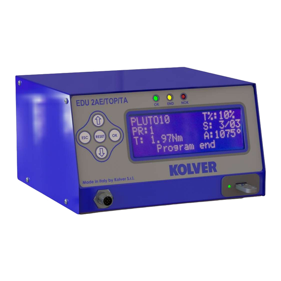
EDU 2AE/TOP/NT - EDU 2AE/TOP/NT/E -
CONTROL UNIT MODEL: EDU 2AE TOP/NT - EDU 2AE TOP/NT/E - EDU 2AE TOP/NT/TA
TRANSFORMER: 230V or 110V AC 50 Hz – 40 V DC 200 VA FUSE: 3,15 A
KOLVER S.r.l. declares that the new tool here described : control unit model EDU 2AE/TOP is in conformity
with the following standards and other normative documents : 2006/42/CE, 2006/95/CE, 2004/108/CE, EN
60745-1, EN 60204-1, EN 61000-6-1, EN 61000-6-3.
It is also in conformity with the RoHS II normative.
Name:
Position:
st
Thiene, Jan. 1
2015
MANUAL
EDU 2AE/TOP/NT/TA
Torque range: 0.01-0.15 Nm
IDENTIFICATION DATA OF THE MANUFACTURER
U
VIA M. CORNER, 19/21
36016 THIENE (VI) ITALIA
IDENTIFICATION DATA OF THE PRODUCT
U
CODE: 031000/TOP/NT - 031000/TOP/NT/E - 031000/TOP/NT/TA
TECHNICAL DATA OF THE PRODUCT
DIMENSIONS: 190 x 205 x h120 mm WEIGHT: 4 Kg
DECLARATION OF CONFORMITY
Giovanni Colasante
General Manager
Person authorized to compile the technical file in Kolver
KOLVER S.r.l.
Giovanni Colasante
Advertisement
Table of Contents

Related Manuals for Kolver EDU 2AE/TOP/NT


Summary of Contents for Kolver EDU 2AE/TOP/NT
- Page 1 DIMENSIONS: 190 x 205 x h120 mm WEIGHT: 4 Kg DECLARATION OF CONFORMITY KOLVER S.r.l. declares that the new tool here described : control unit model EDU 2AE/TOP is in conformity with the following standards and other normative documents : 2006/42/CE, 2006/95/CE, 2004/108/CE, EN 60745-1, EN 60204-1, EN 61000-6-1, EN 61000-6-3.
- Page 2 EDU 2AE/TOP/NT power supply and control units are an innovative system for controlling the torque of any current control NATO electric screwdrivers. EDU 2AE/TOP/NT delivers all the advantages of precision torque control electric tools at a fraction of the price of transdurized tools.
-
Page 3: Program Setting
FRONT PANEL KEYBOARD To enter the menu press the ESC key for 2 seconds. Select the line by pressing then press OK (the symbol will turn into ). Press the to select the required value and then confirm through OK (or ESC if you don’t want to save the value). -
Page 4: Program Menu
AVAILABLE ON EDU 2AE/TOP/NATO/E and EDU 2AE/TOP/NATO/TA VERSIONS ONLY USB Options: you can view, upload and create programs setting It indicates the menu section where of the control unit. PROGRAM MENU: The first 28 menu lines are available in both the EDU 2AE/TOP and EDU 2AE/TOP/TA models. Lines from 29 to 32 are only available in the TOP/TA model. - Page 5 - - - - - M E N U - - P R : 1 - - - - - 6 ) B r a k e t i m e : o f f 7 ) R a m p : 0 .
- Page 6 ATTENTION: If torque isn’t reached by the maximum time, the screwdriver will stop. “Over maximum time” will be displayed on the status bar and the red led will light up. You will hear two beep sounds, too. - - - - - M E N U - - P R : 1 - - - - - 1 2 ) P r e R e v : o f f...
- Page 7 - - - - - M E N U - - P R : 1 - - - - - 1 8 ) P r e s s O K : o f f 1 9 ) P r e s s E S C : o f f ...
- Page 8 The selection of the torque value is carried out by entering the digit cell by cell. 26) Torq max – Maximum Torque: The minimum torque and maximum torque options allow the user to set the acceptable torque range for the single application. When the reached torque is within this range, “Screw OK”...
-
Page 9: Sequence Menu
32) Ang. max - Maximum angle: Maximum angle threshold. You can set it when T&A is set on Tor, T/in or T/lv (see T&A specific instructions). The maximum angle the operator can set is 9720°. When T&A is set on Ang., A/in or A/lv mode, maximum angle corresponds to the angle that has to be carried out. -
Page 10: Option Menu
6) Reset seq.: When ON, you can reset the Sequence (pushing the Reset button). 7) Aut. res seq- Automatic Reset Sequence: When ON, the control unit automatically resets after the end of the sequence. When OFF it is necessary to press OK at the end of each sequence. OPTION MENU: - - - - - M A I N - M E N U - - - - - - S e q u e n c e... -
Page 11: Usb Options
- - - - O P T I O N S - M E N U - - - - 6 ) V e r s i o n s 7 ) S e r i a l n . 0 0 0 0 0 0 0 0 ... -
Page 12: Torque Calibration
S a v e S E T 0 0 . K OL c o n f i r m E S C q u i t Info USB: press OK and see the loaded program. You can see the loaded program only if you have saved the program in your USB drive as named as SETxx.KOL. - Page 13 - - - - - - - - S T E P - - 2 - - - - - E n t e r t h e p e r c e n t a g e 2 0 % 5.
- Page 14 WARNING: Calibration values will be referred to the parameters of the control unit which are set during calibration, i.e. if you modify speed or type of joint, the unit will need to be recalibrated. During calibration when a screwing is not carried out correctly or if for any reasons you’re not sure of the torque value it is possible to repeat it.
- Page 15 TORQUE/LEVER (T/LV): No threshold is preset by the operator: the angle value that appears on the display corresponds to the angle that is carried out starting from the moment in which the lever is pressed until the torque is reached. ...
- Page 16 ANGLE/LEVER (A/LV): the threshold torque value can’t be set by the operator and the angle value that appears on the display corresponds to the angle that is carried out starting from the moment in which the lever is pressed. INTERPRETATION OF ACOUSTIC SIGNALS The control unit emits sounds which help you understand if the screwing has been carried out correctly or not.
- Page 17 I/O CONNECTIONS: Page 17...
- Page 18 CN1 CONNECTOR – 10 pins CN1 CONNECTOR – 10 pins CN1 CONNECTOR – 10 pins It is situated on the upper part of the back panel. It is situated on the upper part of the back panel. It is situated on the upper part of the back panel.
- Page 19 CN2 CONNECTOR – 14 pins All of the following pins are input: make a contact with pin 14 to activate them. NAME FUNCTION NOT USED If enabled it stops the motor, enables the error signal and “Error missing MISSING PIECE piece”...
- Page 20 CN3 CONNECTOR – 11 pins All of the following pins are output. NAME FUNCTION This signal works in parallel with the green led on the front panel. GREEN LED This signal works in parallel with the red led on the front panel. RED LED This signal works in parallel with the yellow led on the front panel.
- Page 21 CN4 CONNECTOR – 9 pins All of the following pins are output. NAME FUNCTION It indicates you’re using program 1 OUTPUT 1 It indicates you’re using program 2 OUTPUT 2 It indicates you’re using program 3 OUTPUT 3 It indicates you’re using program 4 OUTPUT 4 It indicates you’re using program 5 OUTPUT 5...
- Page 22 CN5 CONNECTOR (25 pin connector - female): NAME FUNCTION Common to every input. Signals have to be enabled making contact between COM 0V the desired signal and this pin (common 0VDC). Not used It indicates stop motor is enabled STOP MOTOR OUT It indicates you’re using program 8 OUTPUT 8...
-
Page 23: Troubleshooting
ERROR PROBLEM SOLUTION “waiting connection” doesn’t turn into “loading” Contact the nearest Kolver dealer. after it’s been switched on. “tightened screw” is displayed on the status bar (the torque signal is displayed during the motor startup process which lasted 0.3 sec). - Page 24 H is > 15 - Unscrewing too heavy A for at least 500 ms) ATTENTION: IF THE OK/ESC OPTION IS DISABLED, ERRORS RESET AT THE FOLLOWING SCREW/PROGRAM. OTHERWISE PRESS ESC. IF THE PROBLEM PERSISTS, PLEASE CONTACT YOUR NEAREST KOLVER DEALER. Page 24...
- Page 25 RX, PIN 5 = GND) and a mini USB connector. You can print the results of each screwing on PC (for example through Hyper Terminal or EDU EXPAND programs) and/or a printer (for example Kolver model PRNTR1). You can also save those results on a USB device (only on EDU2AE/TOP/NATO/E and EDU2AE/TOP/NATO/TA).
- Page 26 Screw: Number of screws = number of tightened screws/total number of screws. Seq: Sequence stage = it indicates the stage of the sequence. T: Torque = torque value. A: Angle = angle value. Notice = in case of program end, it prints “Program End”, in case of sequence end, it prints “Seq. end” or it indicates the type of error (see paragraph: trouble shooting).
- Page 27 EDU EXPAND EDU EXPAND is the software for pc created by Kolver to set, change and save all parameters of EDU2AE/TOP/NATO/E or EDU2AE/TOP/NATO/TA unit. It communicates with the control unit via miniUSB or RS232 and makes you create up to 100 different settings configurations, save them on your USB drive and then recall on your EDU unit.
- Page 28 Here is the main screen when a program has been recalled or when you are creating a new one. To modify or enter any parameter values, double click a cell, select a number within the proper range, then press Enter. If the value is not within its valid range, pressing Enter will not confirm the change.
- Page 29 Click Scan ports to locate the unit. EDU EXPAND recalls the port, the model of the control unit Click Scan ports to locate the unit. EDU EXPAND recalls the port, the model of the control unit Click Scan ports to locate the unit. EDU EXPAND recalls the port, the model of the control unit and its serial number.
- Page 30 7. No one, whether an agent, servant or employee of KOLVER, is authorized to add to or modify the terms of this limited guarantee in any way. However it’s possible to extend the warranty with an extra cost.
Need help?
Do you have a question about the EDU 2AE/TOP/NT and is the answer not in the manual?
Questions and answers