Kolver EDU 2AE Series Operational Manual
Hide thumbs
Also See for EDU 2AE Series:
- Operational manual (21 pages) ,
- Manual (16 pages) ,
- Operational manual (168 pages)
Advertisement
KOLVER S.r.l. declares that the new tool here described : control unit model EDU 2AE is in conformity with
the following standards and other normative documents:
2006/42/CE, LVD 2014/35/UE, EMCD 2014/30/UE, EN 62841-2-2:2014, EN 62841-1: 2015, EN 60204-1,
EN 61000-6-2, EN 61000-6-4.
It is also in conformity with RoHS III normative (2011/65/UE and following 2015/863).
Name:
Position:
st
Thiene, January 1
2023
Operational Manual
EDU2AE/HP
Torque range: 0.35-70 Nm
IDENTIFICATION DATA OF THE MANUFACTURER
U
VIA M. CORNER, 19/21
36016 THIENE (VI) ITALIA
IDENTIFICATION DATA OF THE PRODUCT
U
MODEL:
CODE:
TECHNICAL DATA OF THE PRODUCT
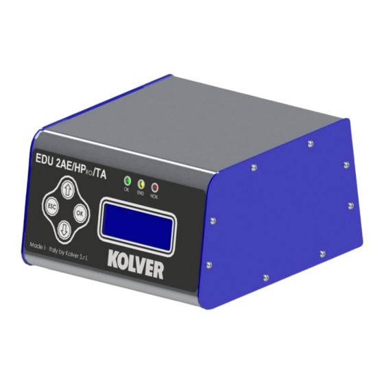
DIMENSIONS: 195 x 170 x h110 mm WEIGHT: 2,4 Kg
DECLARATION OF CONFORMITY
Giovanni Colasante
General Manager
Person authorized to compile the technical file in Kolver.
/TA
RO
KOLVER S.r.l.
EDU2AE/HP
034000/HPRO/TA
FUSE: 3.15 A
/TA
RO
Giovanni Colasante
Advertisement
Table of Contents

Related Manuals for Kolver EDU 2AE Series


Summary of Contents for Kolver EDU 2AE Series
- Page 1 DIMENSIONS: 195 x 170 x h110 mm WEIGHT: 2,4 Kg DECLARATION OF CONFORMITY KOLVER S.r.l. declares that the new tool here described : control unit model EDU 2AE is in conformity with the following standards and other normative documents: 2006/42/CE, LVD 2014/35/UE, EMCD 2014/30/UE, EN 62841-2-2:2014, EN 62841-1: 2015, EN 60204-1, EN 61000-6-2, EN 61000-6-4.
- Page 2 Read the menu description carefully and in case of doubt please contact Kolver for support information. Turn the unit on through the on/off switch on the back panel. The unit will carry a general system check and “waiting connection”...
- Page 3 P L U T O 1 0 T % : 2 0 % 6 0 0 r p m 0 / 0 3 - - - r e a d y 1- Screwdriver model 2- Pre-set torque level (percentage) 3- Selected speed 4- Screw count: fastened screws/total screws 5- Reached torque level Sin Nm, in.lbs or kgf.cm.
-
Page 4: Program Setting
MENU - - - - - M A I N - M E N U - - - - - - c h a n g e E S C q u i t P r o g r a m s e t t i n g ... - Page 5 On the other hand, if you wish to see an error signal during the preset torque in the ramp phase, you can change the minimum time by setting value which is equal or superior to the ramp value (see point 8). 4) Torque: you can select the desired torque as a percentage of the torque range of the selected screwdriver.
- Page 6 9) Final Spd (Final Speed): You can select any speed value of the screwdriver between the maximum and the minimum specific speed of every single screwdriver (see table with technical data). 10) Run time: You can set the time of a tightening, from OFF to 20.0 sec. When the pre-set time has been reached, it results in a torque signal.
- Page 7 16) Rev torque – Unscrewing torque: You can select the desired torque as a percentage of the torque range of the selected screwdriver (see point 2). If the torque is set on MAX, the unscrewing torque is about 20% higher than the possible maximum torque, so that it is always possible to unscrew the tightened screw (we suggest leaving this function on in normal use).
- Page 8 - - - - - - - - M E N U - - - - - - - - 2 1 ) T o r q m i n : 0 . 0 0 N m 2 2 ) T o r q m a x : 2 0 . 0 0 N m ...
-
Page 9: Unit Options
Unit Options - - - - O P T I O N S - M E N U - - - - c h a n g e E S C q u i t 1 ) L a n g u a g e : 2 ) V e r s i o n s 1) Language: This option allows to select among 4 languages: English, French, German, Italian, Spanish and Portuguese. -
Page 10: Torque Calibration
- - - - O P T I O N S - M E N U - - - - 8 ) P r e s s E S C : o f f 9 ) R i l e v . m o d e l . : A u t o ... - Page 11 3. Press OK to confirm. If you choose OFF, calibration will be interrupted and no torque value will be displayed. You choose ON, calibration will continue and the following screen will be displayed: - - - - - - - - S T E P - - 1 - - - - - E n t e r p e r c e n t a g e M I N...
- Page 12 WARNING: Calibration values will be referred to the parameters of the control unit which are set during calibration, i.e. if you modify speed or torque, the unit will need to be recalibrated. During calibration when a screwing is not carried out correctly or if for any reason you’re not sure of the torque value it is possible to repeat it.
- Page 13 TORQUE/INPUT (T/IN): It corresponds to Torque mode, except for the threshold torque which can’t be set by the operator: in fact the value is the result of an external impulse through a proper contact (see paragraph “connections”). It can be very useful if the operator wants the control unit to start counting the angle from a position which is indicated by a precision instrument.
- Page 14 ANGLE/INPUT (A/IN): The threshold can’t be set by the operator: in fact the value is the result of an external impulse through a proper contact (see paragraph “connections”). This function can be very useful if the operator wants the screw to rotate a certain number of degrees after reaching a position indicated by a precision instrument.
- Page 15 I/O CONNECTIONS EDU 2AE control unit series have connectors placed on the back panel. These connectors allow to enable functions through inputs and to take signals through outputs. The inputs are activated by connecting them to ground. A positive voltage must NEVER be brought to these inputs. Bringing 24V to the unit inputs could damage the inputs themselves.
- Page 16 Vers. 120723...
- Page 17 • CN1 CONNECTOR – 10 pin: On the back panel, in all the EDU 2AE units, there is a 10 pin I/O connector. NAME FUNCTION OUTPUT +24V voltage protected. The maximum current consumption is 400mA. CAN NOT BE +24V USED TO POWER EXTERNAL DEVICES. Common pin.
- Page 18 NOT USED Not used Remote motor stop. If it’s activated the message “STOP MOTOR ON” appears on the STOP display. The motor will stop and won’t start working again as long as the contact is closed. MOTOR REVERSE Remote motor start with torque control while unscrewing. START Remote start with torque control while screwing.
-
Page 19: Troubleshooting
ERROR PROBLEM SOLUTION “Waiting connection” doesn’t turn into “system Contact your nearest Kolver dealer. ready” after it’s been switched on. “Error Torque Control” is displayed on the status Make a new screw. If the error persists, change the torque and speed settings. - Page 20 “Rev. incomplete” is displayed on the status bar (the displayed torque signal is correct but the set unscrewing is not complete). “Pre-reverse incompl.” is displayed on the status bar (the lever has been released before the Pre-Rev. has been completed). “Under min time”...
-
Page 21: Serial Port
ATTENTION: IF THE OK/ESC OPTION IS DISABLED, ERRORS RESET AT THE FOLLOWING SCREWING/PROGRAM. OTHERWISE PRESS ESC. IF THE PROBLEM PERSISTS, PLEASE CONTACT YOUR NEAREST KOLVER DEALER. SERIAL PORT: EDU 2AE/HPRO/TA control unit is supplied with a serial 9 pin male connector. In this way you can print the results of each screwing. - Page 22 EXPLODED VIEW EDU2AE/HPRO/TA Vers. 120723...
-
Page 23: Spare Parts
SPARE PARTS Position Description Code FRONT MEMBRANE HPRO/TA (BLACK) 858004 818009-TA FRONT PANEL EDU2AE/HPRO 818015 WASHER M3 800042 SPACER 15mm 890004/T DISPLAY BOARD 852522 NUT M3 800056 SCREW M3 X 5 ZN TX10 872444 SIDE EDU 2AE/HPRO (BLUE) 818013 BOARD SUPPORT 872442 MAIN BOARD 852521/SW... - Page 24 7. No one, whether an agent, servant or employee of KOLVER, is authorized to add to or modify the terms of this limited guarantee in any way. However it’s possible to extend the warranty with an extra cost.
Need help?
Do you have a question about the EDU 2AE Series and is the answer not in the manual?
Questions and answers