Table of Contents
Advertisement
Quick Links
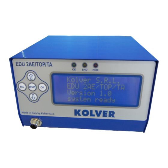
EDU 2AE/TOP e EDU 2AE/TOP/TA
TRANSFORMER: 230V or 110V AC 50 Hz – 40 V DC 200 VA FUSE: 3,15 A
KOLVER S.r.l. declares that the new tool here described : control unit model EDU 2AE is in conformity with
the following standards and other normative documents : 2006/42/CE, 2006/95/CE, 2004/108/CE, EN 60745-1,
EN 60204-1, EN 61000-6-1, EN 61000-6-3.
It is also in conformity with the RoHS II normative.
Name:
Position:
nd
Thiene, May 2
, 2013
MANUAL
Torque range: 0.4-35 Nm
I DENTIFICATION DATA OF THE MANUFACTURER
U
VIA M. CORNER, 19/21
36016 THIENE (VI) ITALIA
I DENTIFICATION DATA OF THE PRODUCT
U
CONTROL UNIT MODEL: EDU 2AE TOP - EDU 2AE TOP/TA
CODE: 031000/TOP - 031000/TOP/TA
TECHNICAL DATA OF THE PRODUCT
DIMENSIONS: 190 x 205 x h120 mm WEIGHT: 4 Kg
DECLARATION OF CONFORMITY
Giovanni Colasante
General Manager
Person authorized to compile the technical file in Kolver
KOLVER S.r.l.
Giovanni Colasante
Advertisement
Table of Contents


Need help?
Do you have a question about the FAB Series and is the answer not in the manual?
Questions and answers