Table of Contents
Advertisement
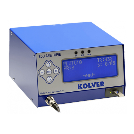
EDU 2AE/TOP - EDU 2AE/TOP/E -
MODEL:
CODE:
KOLVER S.r.l. declares that the new tool here described: control unit model EDU2AE/TOP and
EDU2AE/TOP/TA is in conformity with the following standards and other normative documents: 2006/42/CE,
LVD 2014/35/UE, EMCD 2014/30/UE, EN 280519, EN 60204-1, EN 61000-6-2, EN 61000-6-3.
It is also in conformity with RoHS III normative (2011/65/UE and following 2015/863).
Name:
Position:
st
Thiene, January 1
2020
MANUAL
EDU 2AE/TOP/TA 5.00
Torque range: 0.2-50 Nm
IDENTIFICATION DATA OF THE MANUFACTURER
U
VIA M. CORNER, 19/21
36016 THIENE (VI) ITALIA
IDENTIFICATION DATA OF THE PRODUCT
U
EDU 2AE/TOP
032000/TOP
TECHNICAL DATA OF THE PRODUCT
DIMENSIONS: 190 x 205 x h120 mm WEIGHT: 2,5 Kg
DECLARATION OF CONFORMITY
Giovanni Colasante
General Manager
Person authorized to compile the technical file in Kolver
KOLVER S.r.l.
EDU2AE/TOP/E
032000/TOP/E
FUSE: 3,15 A
Giovanni Colasante
EDU2AE/TOP/TA
032000/TOP/TA
Advertisement
Table of Contents


Need help?
Do you have a question about the EDU 2AE/TOP/E and is the answer not in the manual?
Questions and answers