
Subscribe to Our Youtube Channel
Related Manuals for SMC Networks EX245-FPS1


Summary of Contents for SMC Networks EX245-FPS1
- Page 1 No.EX##-OMY0004 PRODUCT NAME SI Unit MODEL / Series EX245-FPS1 EX245-FPS2 EX245-FPS3 PRODUCT NAME Digital Input Module MODEL / Series EX245-DX1 PRODUCT NAME Digital Output Module MODEL / Series EX245-DY1...
-
Page 2: Important
Original Instructions IMPORTANT This manual is only valid for the EX245-FPS1/2/3 with the following hardware and firmware versions. Firmware version (FW) : 2.1.X Hardware version (HW) : 03 and higher FW version details 2. 1. X First digit:... -
Page 3: Table Of Contents
Contents IMPORTANT ....................1 Contents ...................... 2 1. Safety Instructions ................... 4 2. For your safety ..................10 2.1. General safety notes ........................10 2.2. Electrical safety ..........................11 2.3. Safety of the machine or system ....................12 2.4. Directive and standards ......................... 12 2.5. - Page 4 13.1. Markers ............................80 13.2. Y Connector ..........................81 13.3. Seal cap ............................82 14. Dimensions ..................83 14.1. EX245-FPS1/2/3 .......................... 83 14.2. I/O Modules Manifold ........................85 15. Troubleshooting ................... 86 15.1. EX245-FPS1/2/3 .......................... 86 15.2. EX245-DX1 ..........................88 15.3.
-
Page 5: Safety Instructions
1. Safety Instructions These safety instructions are intended to prevent hazardous situations and/or equipment damage. These instructions indicate the level of potential hazard with the labels of "Caution", "Warning" or "Danger". They are all important notes for safety and must be followed in addition to International Standards (ISO/IEC) , and other safety regulations. - Page 6 1. Safety Instructions Caution 1.The product is provided for use in manufacturing industries. The product herein described is basically provided for peaceful use in manufacturing industries. If considering using the product in other industries, consult SMC beforehand and exchange specifications or a contract if necessary. If anything is unclear, contact your nearest sales branch.
- Page 7 Operator This operation manual has been written for those who have knowledge of machinery and apparatus that use pneumatic equipment and have full knowledge of assembly, operation and maintenance of such equipment. Please read this operation manual carefully and understand it before assembling, operating or providing maintenance to the product.
- Page 8 ■NOTE ○Follow the instructions given below when designing, selecting and handling the product. The instructions on design and selection (installation, wiring, environment, adjustment, operation, maintenance, etc.) described below must also be followed. Product specifications Use the specified voltage. Otherwise failure or malfunction can result. Reserve a space for maintenance.
- Page 9 Environment Select the proper type of protection according to the environment of operation. IP65 protection is achieved when the following conditions are met. (1) Connectors that are not used must be closed with covering caps. (2) All covering caps must be screwed down correctly after wiring and setting has been completed. (3) Apply the recommended tightening torque and all manifold parts must be installed correctly.
- Page 10 Maintenance Turn off the power supply, stop the supplied air, exhaust the residual pressure and verify the release of air before performing maintenance. There is a risk of unexpected malfunction. Perform regular maintenance and inspections. There is a risk of unexpected malfunction. After maintenance is complete, perform appropriate functional inspections.
-
Page 11: For Your Safety
Validity of the user manual This user manual is valid for the EX245-FPS1/2/3 module in the version indicated on the inner cover page, as well as for the same or later versions if replaced with the devices of the same type. -
Page 12: Electrical Safety
Do not carry out any repairs or modifications 2.1.5. It is prohibited for the user to carry out repair work or make modifications to the module. The housing must not be opened. The module is protected against tampering by means of security labels. The security label is damaged in the event of unauthorized repairs or opening of the housing. -
Page 13: Safety Of The Machine Or System
Intended use 2.4.1. The EX245-FPS1/2/3 module is designed exclusively for use in a PROFIsafe system and fulfils the PROFINET guidelines as defined by PI (PNO). It can only perform its tasks in the system if it is used according to the specifications in this document. -
Page 14: Documentation
2.5. Documentation Correctness and availability of documentation 2.5.1. Always use the latest documentation for this product. Changes or additions to documentation can be found on the Internet (see: www.smcworld.com) PROFIsafe user manuals: 2.5.2. For the safe controller used For the failsafe PROFIsafe I/O modules used For PROFIsafe system function blocks Observe the information on PROFINET, and PROFIsafe which is available on the Internet (see: www.profisafe.net). -
Page 15: Product Summary
IP65 protection Two connectors for PROFINET IO and two connectors (24 Volt) for supply voltages EX245-FPS1: 2 x Push Pull connectors and 2 x Push Pull connectors (SCRJ) EX245-FPS2: 2 x Push Pull connectors and 2 x Push Pull connectors (RJ45) EX245-FPS3: 2 x 7/8 inch 5pins connectors and 2 x M12 4 pins socket D-coded connectors Four separately controlled safe power supplies (3 for valve zones &... -
Page 16: Structure
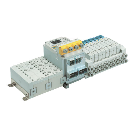
3.2. Structure 1. SI Unit EX245-FPS1/2/3 2. Digital Input Module EX245-DX1 3. Digital Output Module EX245-DY1 5. Solenoid valves 4. End plate EX245-EA2-1 Components Function Fieldbus, Safety Digital Input, Safe power supply for valve interface and SI Unit supply voltage to modules... -
Page 17: Safe Digital Inputs And Clock Outputs Ut1 And Ut2
3.3. Safe digital inputs and clock outputs UT1 and UT2 Safe digital inputs 3.3.1. The module has safe digital inputs, which can be used as follows: For two-channel assignment: four two-channel inputs For single-channel assignment: eight single-channel inputs Or a combination of two and single channel inputs. Technical data for the safe inputs: see Section 10.4 “Safe digital inputs”. - Page 18 Clock outputs UT1 and UT2 3.3.5. The module has two independent clock outputs. These clock outputs provide the supply voltage for the safe inputs. Both clock outputs provide a pulse pattern to detect cross circuits in the external wiring of the inputs if Cross circuit detection has been activated for at least one input pair.
- Page 19 Cross circuit detection If all inputs are parameterized without cross circuit detection, a DC voltage can be sourced at the clock outputs without clock pulses. As soon as cross –circuit detection has been parameterized for at least one input pair, pulses are output at clock outputs UT1 and UT2. For inputs that are parameterized with cross –circuit detection, the default assignment is as follows: Inputs for channel 1 (IN0 - IN3) are assigned to clock output UT1.
- Page 20 Safe state 3.3.8. The safe state for the module is the transmission of the value “0” in the image of the inputs to the safe controller. The safe state for the F-Input data is “0”. Passivation results in a change to the safe state: see “Passivation”...
-
Page 21: Safe Power Supply (Outputs)
The following serious errors result in the safe state: Serious hardware faults in the internal circuit User errors Module overload Module overheating Incorrect supply The diagnostic message is transmitted to the controller: see Section 16 “Error codes for Diagnostic Messages”. WARNING: Loss of safety function Sequential errors can result in the loss of the safety function In the event of a device error, the module should be disconnected completely from the power... -
Page 22: General Specifications
4. General Specifications Table 4-1 EX245 series general specifications Item Specification Rated voltage 24 V DC +20% -15% Supply interruption for no loss of function 1 ms maximum IP65 (when fully installed or fitted with protective cover) Protection class (complies with IEC 60529) 10 Mohm @ 500 VAC between FE and all accessible terminals to Insulation resistance IEC 61131-2. -
Page 23: Power Supply Concept
5. Power Supply Concept 5.1. Power distribution In the EX245 PROFIsafe product series, the supply for the logic input modules and hence sensors is designated “US1” The supply for the valves and logic output modules and hence loads is designated “US2”. To provide the safety function, the “US2”... -
Page 24: Under-Voltage Detection
5.2. Under-voltage detection LED indicator 5.2.1. US1 indicator shows the status of the supply for the logic/sensors. US2 indicator shows the status of the supply (US2) for the valves/loads. The status of the load supply is reflected in the diagnostic data. Diagnostic data 5.2.2. -
Page 25: Valve Manifold
6. Valve Manifold The EX245 PROFIsafe product series can be used with various valve manifolds. For full details refer to the respective product documentation. Pin assignments for this connector are shown in the table below Pin No. Valve Zone Signal Name Function Common M OUT 1... -
Page 26: Installation
7. Installation 7.1. Mounting Caution To prevent manifold components being damaged, apply the recommended tightening torque. Mount the manifold using the 8 mounting positions on the base with screws. Required screws are as follows: ① 2 x M5 (End plate: torque = 1.5 Nm) ②... - Page 27 Valve manifold connection 7.1.1. Connect the valve manifold with the 2 screws on the SI Unit. (hexagonal socket wrench size 2.5) Torque = 0.6 Nm O-ring Fig. 7-2 Valve manifold connection Caution For a protection rating of IP65 to be ensured, apply the recommended tightening torque and make sure that the O-ring is positioned correctly on the screw.
-
Page 28: Wiring
④ Push Pull connector (24 Volt), Power connection (XD1) ⑤ Push Pull connector (24 Volt), Power connection (XD2) ⑥ M12 Connector, Safe Inputs ① ⑥ ② ③ ④ ⑤ Fig. 7-4 Screw and connector allocation (EX245-FPS1/2) - 27 - No.EX##-OMY0004... - Page 29 ① M5, FE terminal screw (torque = 1.5 Nm) ② M12 connector, PROFINET connection Port1 (XF1), Port type: MDI ③ M12 connector, PROFINET connection Port2 (XF2), Port type: MDI-X ④ 7/8 inch connector, Power connection (XD1) ⑤ 7/8 inch connector, Power connection (XD2) ⑥...
- Page 30 Section 2.2.2 of this manual. Maximum loop through current between connectors must not be exceeded. Refer to EX245-FPS1/2/3 specifications table for details The SI unit makes use of a CLASS 1 LASER product. Do not stare into beam visible at XF1 and XF2...
- Page 31 PROFINET communication Remarks TX Transmit Data RX Receive Data (View of the SCRJ Socket) Fig. 7-8 Pin allocation of PROFINET SCRJ communication connectors for EX245-FPS1 Port1 (XF1) Port2 (XF2) Port type: MDI Port type: MDI-X TD+ Transmit Data RD+ Receive Data...
- Page 32 Note ・ If a copper communications cable is used and the “Disable autonegotation” option is selected, you must select the correct network cable, refer to Fig 7-11, 7-12, 7-13. ・ Auto crossover function is not available when the ‘Disable autonegotiation’ option is selected. ・...
- Page 33 Connection example Case 1 Case 2 Fig. 7-13 Connection examples when “Disable autonegotiation” is selected FE terminal 7.2.2. The SI Unit must be connected to FE (Functional Earth) to divert electromagnetic interference. Connect the grounding cable using the FE terminal screw on the SI Unit. The other end of the grounding cable should be terminated to ground potential.
-
Page 34: Commissioning
The choice of operating mode (Commissioning Mode or Safety Mode) is user selectable and must match the setting of the 2-bit DIP switch. Refer to 10.11.2 When used in Safety Mode the EX245-FPS1/2/3 can be configured how to react when a safety related fault is detected. ... - Page 35 8.1.3.1. Safety Mode (Channel Passivation) - Safe digital I/O (SM) Parameter settings are transferred by the engineering tool (e.g. Siemens TIA Portal) when the project is downloaded from the programming station to the EX245-FPS1/2/3 8.1.3.2. Safety Mode (Module Passivation/xxx) - Safe digital I/O (SM/M) Parameter settings are contained within the process image and occupy 8 bytes of user settable output data.
- Page 36 Enter the modules in your configuration program corresponding to the actual module layout and a "Diagnostics type" module if required. If the configuration does not match the actual layout, the connection to the IO Controller will not be established and the EX245-FPS1/2/3 error LEDs will flash. Configuration steps: Enter one of the “Diagnostics type”...
-
Page 37: Parameterisation
8.2. Parameterisation 8.2.1. PROFIsafe Parameters (F-Parameters) Table 8-3 F-Parameter details Parameter Range Default Type of parameter F_SIL SIL3 SIL3 Static F_Block_ID 0 to 7 Static F_Par_Version Static F_Source_address Automatic Static F_Destination_address 1 to 1023 1 (factory default setting) Static F_WD_Time 10 to 10,000 ms 150 ms Static... - Page 38 8.2.2.4. Module parameters for safe inputs in Safety Mode (Channel Passivation) Parameter tree (overview) Note: Parameters for ‘Input Connector 1..3’ are identical to parameters for Input Connector 0 For Safety Mode (Module Passivation/xxx), please refer to section 10.6 for details on how configure the parameters.
- Page 39 Module parameters for Safe inputs parameter details in Safety Mode (Channel Passivation) Table 8-4 Safe inputs parameter details in Safety Mode (Channel Passivation) Type of Parameter Range Default parameter Sensor power supply (Clock configuration) UT1 clock pulse Disable, Enable Enable Static UT2 clock pulse Disable, Enable...
- Page 40 Parameters for connected sensors (Sensor evaluation) The EX245 can evaluate input signals of several types of sensors, for example, one channel sensor, two channel equivalent or non-equivalent sensor. Parameters must be assigned according to the connected sensor. The parameter specifies how to evaluate the sensor input signal in EX245. When it is “1oo1”...
- Page 41 Parameters for discrepancy between two channel input signals Discrepancy between two input signals is evaluated in the EX245 when “1oo2” is specified. Diagnostics information is sent when the time difference between a change of state in the two input signals exceeds the specified discrepancy time. The parameter specifies the maximum amount of time that should elapse between a change of state in two inputs.
- Page 42 Start inhibit after discrepancy The parameter specifies behaviour of an input bit after detecting a discrepancy between input ch1 and ch2. When set to “Disable”, the input bit will still change after a discrepancy is detected. When set to “Enable”, the input bit retains the last value (i.e., “0”). Until an acknowledgement is received from the controller.
- Page 43 8.2.2.5. Module parameter for power supplies for zones and modules in Safety Mode (Channel Passivation) The status of the pilot pressure related to the respective safe power supply for the valve zone or IO modules can be checked. Parameter tree (overview) For Safety Mode (Module Passivation/xxx), please refer to section 10.6 for details on how to configure...
- Page 44 Output feedback parameter If the parameter is enabled, the EX245 evaluates the bit status of a safe input according to the status of the safe power supply. Relationship between safe power supplies and safe inputs If the parameter is enabled, the relationship in the following table between the safe power supply and safe input is applied.
-
Page 45: Diagnosis
9.1. Diagnostics data on I/O mapping The EX245-FPS1/2/3 can be allocated diagnostics data as digital input data on I/O mapping, if one of the modules, “Diagnostics type 1” or “Diagnostics type 2”, is used. Use the PROFIsafe master’s software to select a diagnostics module type to allocate the diagnostics data on I/O mapping. - Page 46 9.1.1.2. General diagnostics 2 Table 9-3 General diagnostics 2 Description Explanation Module 1 error 0: No error or not connected, 1: Module 1 has an error Module 2 error 0: No error or not connected, 1: Module 2 has an error Module 3 error 0: No error or not connected, 1: Module 3 has an error Module 4 error...
- Page 47 9.1.1.5. Valve diagnostics 3 Table 9-6 Valve diagnostics 3 Description Explanation Valve Zone 3, coil 1 diagnostic 0: No error, 1: Fault Valve Zone 3, coil 2 diagnostic 0: No error, 1: Fault Valve Zone 3, coil 3 diagnostic 0: No error, 1: Fault ...
- Page 48 9.1.2.2. Valve diagnostics 1 Table 9-9 Valve diagnostics 1 Description Explanation Valve 0, 1 diagnostics 0: Short circuit, 1: No error Valve 2, 3 diagnostics 0: Short circuit, 1: No error Valve 4, 5 diagnostics 0: Short circuit, 1: No error Valve 6, 7 diagnostics 0: Short circuit, 1: No error Valve 8, 9 diagnostics...
-
Page 49: Maintenance Alarm For The Fibre-Optic Cables
"Maintenance alarm" for the Fibre-optic cable, if monitor setting of communication port is enabled. If the FO LED of the EX245-FPS1 is flashing (more than 0 dB but less than 2 dB) or ON (the margin is 0 dB), refer to the Section 10.8.1.5. -
Page 50: Unit
LED indicators 1 EX245-FPS2: RJ45 Switch cover Connector label Production label Mounting hole Power connection (XD2) Push Pull connectors (24 Volt) Power connection (XD1) Push Pull connectors (24 Volt) Fig. 10-1 Allocation of parts on the EX245-FPS1/2 - 49 - No.EX##-OMY0004... - Page 51 EX245-FPS3 Safe input connection 4 x M12, 5-way sockets PROFINET connection for Port1 (XF1) LED indicators 1 M12, 4pins socket, D-coded connector LED indicators 2 PROFINET connection for Port2 (XF2) M12, 4pins socket, D-coded connector Switch cover Production label Mounting hole Power connection (XD1) Power connection (XD2) 7/8 inch, 5pins plug connector (24 Volt)
-
Page 52: Specifications
10.2. Specifications Table 10-1 specifications Description Item EX245-FPS1 EX245-FPS2 EX245-FPS3 General Dimensions (W x L x H) mm 85 x 148.5 x 136 Weight 1,100 g or less 1,200 g or less Housing material Aluminium Max. number of modules Max. number of digital inputs 128 (independent of safe inputs) Max. - Page 53 Item Description Safe power supply 3 zones Number of outputs 0 VDC switch is common for all 3 zones Fixed 8 valve coils Number of valve coils per zone For valve Short circuit protection 1.5 A in total Max current From US2 Power source Number of outputs...
-
Page 54: Wiring
10.3. Wiring Caution ●To prevent damage, all power for the SI Unit and modules must be turned off (i.e. de-energized) before the modules are installed or removed. ●For a protection rating of IP65 to be ensured, sockets that are not used must be closed with M12 covering caps. -
Page 55: Safe Digital I/O - Safe Power Supply (Outputs)
10.5. Safe digital I/O - Safe power supply (outputs) For an SI unit configuration using Safety Mode (Channel Passivation), it occupies 5 bytes of Output data as shown below. Table 10-5 Byte 0 Safe power supply for Safety Mode (Channel Passivation) (outputs) Description Explanation Safe power supply of US2 to the IO modules... - Page 56 Table 10-7 Byte 0 Safe power supply for Safety Mode (Module Passivation/xxx) (outputs) Description Explanation Safe power supply of US2 to the IO modules 0: OFF, 1: ON Safe power supply of US2 to the valve zone 1 0: OFF, 1: ON Safe power supply of US2 to the valve zone 2 0: OFF, 1: ON Safe power supply of US2 to the valve zone 3...
- Page 57 Table 10-9 Byte2 Output feedback parameter zone 1 for Safety Mode (Module Passivation/xxx) Bit 2 Bit 1 Bit 0 Value for OFF feedback delay time for zone 1 Same as Table 10-8 Bit 5 Bit 4 Bit 3 Value for ON feedback delay time for zone 1 Same as Table 10-8 Bit 6 Output feedback for Zone 1...
- Page 58 Table 10-11 Byte4 Safe input parameter for Ch.0 and Ch.4 (input connector 0) for Safety Mode (Module Passivation/xxx) Bit 1 Bit 0 Sensor evaluation for Ch.0 and Ch.4 (input connector 0) Disable 1 out of 1 evaluation (Input 0, 4) * 1 out of 2 evaluation, 2-channel equivalent 1 out of 2 evaluation, 2-channel non-equivalent Power source for cross circuit detection and Clock pulse for Ch.0 and Ch.4 (input...
- Page 59 Table 10-13 Byte6 Safe input parameter for Ch.2 and Ch.6 (input connector 2) for Safety Mode (Module Passivation/xxx) Bit 1 Bit 0 Sensor evaluation for Ch.2 and Ch.6 (input connector 2) Disable 1 out of 1 evaluation (Input 2, 6) 1 out of 2 evaluation, 2-channel equivalent 1 out of 2 evaluation, 2-channel non-equivalent Power source for cross circuit detection and Clock pulse for Ch.2 and Ch.6 (input...
-
Page 60: Process Data For Valves
10.7. Process data for valves The SI Unit occupies 3 bytes of output data for valves. The counting of valve coils starts at the SI Unit from left to right. Valve Zone Description Explanation Valve coils 0-7 (of the 1st valve zone) 0: OFF, 1: ON Valve coils 0-7 (of the 2nd valve zone) 0: OFF, 1: ON... - Page 61 Byte 1: Status of the status bit in Byte 0 This indicates if Byte 0 status bits are valid or not Table 10-17 Byte 1 Status of the status bit in Byte 0 Description Explanation Status of status bit for safe output for IO Module 0: invalid, 1: valid Status of status bit for safe output for valve zone 1 0: invalid, 1: valid...
-
Page 62: Led Indicators
Fibre-Optic communication diagnostics for Port 2 (XF2) Orange : When Link LED and Act LED are both on the combined colour may appear to be orange **. Only EX245-FPS1 has this function Fig. 10-4 LED indicators 1 of the EX245-FPS1/2/3 - 61 - No.EX##-OMY0004... - Page 63 10.9.1.1. SF and BF indicators Table 10-19 SF and BF indicators Meaning No fault (The SI Unit is currently exchanging data with the Controller without errors.) Faulty or no connect message frame (although the SI Unit is physically connected to the bus) ●IO configuration is defective, or before initial commissioning has been done.
- Page 64 Status for safe US2 power supply for IO modules Green/Red Z1, Z2, Z3 Status for safe US2 zone power supplies for valves Green/Red Fig. 10-4 LED indicators 2 of the EX245-FPS1/2/3 10.9.2.1. UT1 and UT2 LEDs Table 10-24 UT1 and UT2 LEDs UT1/2 Meaning No error At least one of the safe inputs has a cross circuit with another signal (e.g.
- Page 65 The safe output is switched OFF. LED indicators 3 10.9.3. P LED FS LED Inside the switch cover Fig. 10-5 LED indicators 3 of the EX245-FPS1/2/3 10.9.3.1. FS LED Table 10-27 FS LED LED state Meaning The safety application has valid F-Parameters and i-Parameters...
-
Page 66: Production Label
10.10. Production label Product number MAC address Firmware and Hardware version Firmware version (FW) : 2.1.X Hardware version (HW): 03 and higher Fig. 10-6 Production label 10.11. DIP Switches PROFIsafe address switch 10.11.1. A ten bit DIP-Switch is provided for the safety address setting. The switch setting is only checked at power-up. - Page 67 A two bit DIP-Switch and a six bit DIP-Switch 10.11.2. Two DIP-Switches SW2 and SW3 are under the M12 safe input connector box. To access the switches remove the retaining screws as shown below. Fig. 10-8 Retaining Screws Fig. 10-9 SW3 and SW2 DIP switches When the DIP-Switches have been set ensure the M12 connector block and all retaining screws are refitted.
- Page 68 10.11.2.1. SW2 Not in use. 10.11.2.2. SW3 The two bits of the DIP-Switch “SW3” are used for the commissioning mode (COMNG_MODE). Table 10-29 SW3 details Bit 1 Bit 2 Meaning SM (Safety mode) Failure state Failure state CM (Commissioning mode) ●The setting of the DIP switch SW3 is read during power-up.
-
Page 69: Block Diagram
OUT [16] Push Pull connector (SCRJ) ① ② Port2 (x2) OUT [23] 24 V (US1) 0 V ( US1) Module 24 V (P OUT) interface 0 V (M OUT) Fig. 10-10 Block diagram of the EX245-FPS1 - 68 - No.EX##-OMY0004... - Page 70 Fig. 10-11 Block diagram of the EX245-FPS2 Fig. 10-12 Block diagram of the EX245-FPS3 - 69 - No.EX##-OMY0004...
-
Page 71: Digital Input Module - Ex245-Dx1
11. Digital Input Module - EX245-DX1 11.1. Parts and description Fig. 11-1 Allocation of parts on the EX245-DX1 Note: EX245-DX1 is the new part number for the EX245-DX1-X36 - 70 - No.EX##-OMY0004... -
Page 72: Specifications
11.2. Specifications Table 11-1 EX245-DX1 specifications Item Description General Dimensions (W x L x H) in mm 54 x 120 x 61 Weight 280g or less Housing material Nylon, PBT Electrical Rated supply voltage 24 V DC Voltage drop to sensor supply Max. -
Page 73: Wiring
11.3. Wiring Caution ●To prevent damage, all power for the SI Unit and modules must be turned off (i.e. de-energized) before the modules are installed or removed. ●For a protection rating of IP65 to be ensured, sockets that are not used must be closed with M12 covering caps. -
Page 74: Led Indicators
11.5. LED indicators The status indicators are arranged on the EX245-DX1 as shown in the illustration below. 0 to15 Description Input is not activated and no errors. Green ON Input is activated. Red ON Short circuit is detected. Fig. 11-2 Status indicators of the EX245-DX1 - 73 - No.EX##-OMY0004... -
Page 75: Block Diagram
11.6. Block diagram The following figure shows the block diagram of the EX245-DX1. 8 x M12, 5-way sockets 8 x M12, 5-way sockets (0 to 7) (0 to 7) Short circuit Short circuit ① ① 24 V 24 V protection protection ②... -
Page 76: Digital Output Module - Ex245-Dy1
12. Digital Output Module - EX245-DY1 12.1. Parts and description Fig. 12-1 Allocation of parts on the EX245-DY1 Note: EX245-DY1 is the new part number for the EX245-DY1-X37 - 75 - No.EX##-OMY0004... -
Page 77: Specifications
12.2. Specifications Table 12-1 EX245-DY1 specifications Item Description General Dimensions (W x L x H) in mm 54 x 120 x 61 Weight 280 g or less Housing material Nylon, PBT Electrical Rated supply voltage 24 V DC Voltage drop to load supply Max. -
Page 78: Wiring
12.3. Wiring Caution ●To prevent damage, all power for the SI Unit and modules must be turned off (i.e. de-energized) before the modules are installed or removed. ●For a protection rating of IP65 to be ensured, sockets that are not used must be closed with M12 covering caps. -
Page 79: Led Indicators
12.5. LED indicators The status indicators are arranged on the EX245-DY1 as shown in the illustration below. 0 to 7 Description Output is not activated and no errors. Green ON Output is activated. Red ON Short circuit is detected. Fig. 12-2 Status indicators of the EX245-DY1 - 78 - No.EX##-OMY0004... -
Page 80: Block Diagram
12.6. Block diagram The following figure shows the block diagram of the EX245-DY1. 4 x M12, 5-way sockets 4 x M12, 5-way sockets (0 to 3) (0 to 3) ① ① ① ① N.C. N.C. ② ② ② ② DO (n+1) DO (n+1) Short circuit Short circuit... -
Page 81: Accessories
13. Accessories Markers 13.1. Markers are available in single sheets each containing 88 pieces, For the EX245-DX1 and EX245-DY1 use the part No.EX600-ZT1. Model No.:EX600-ZT1 Fig. 13-1 EX600-ZT1 - 80 - No.EX##-OMY0004... -
Page 82: Y Connector
Y Connector 13.2. Y connectors can be used with the EX245-DX1 and EX245-DY1. There are two options – 2 x M12 to M12 2 x M8 to M12 Model No.:PCA-1557785 (Y branch Connector (2 x M12 to M12)) Fig. 13-2 PCA-1557785 - 81 - No.EX##-OMY0004... -
Page 83: Seal Cap
(Y branch Connector (2 x M8 to M12)) Fig. 13-3 PCA-1557798 13.3. Seal cap Seal caps can be used with the EX245-FPS1/2/3, EX245-DX1, EX245-DY1. Mount the seal cap in the unused socket. IP65 is satisfied by using the seal cap properly. -
Page 84: Dimensions
14. Dimensions 14.1. EX245-FPS1/2/3 The following figure shows the dimensions. EX245-FPS1/2 - 83 - No.EX##-OMY0004... - Page 85 EX245-FPS3 - 84 - No.EX##-OMY0004...
-
Page 86: I/O Modules Manifold
14.2. I/O Modules Manifold Fig. 15-1 Dimensions of the Modules manifold The following table shows the length of the I/O Modules manifold. Table 15-1 Length of the EX245 series module 113.6 167.6 221.6 275.6 329.6 383.6 437.6 491.6 545.6 Formulas: L1 = 54n + 113.6 (max. 8 modules) - 85 - No.EX##-OMY0004... -
Page 87: Troubleshooting
IO Controller available on the bus) ●Auto negotiation not successful. Table 16-2 Troubleshooting for PROFINET communication Problem Possible cause Remedy The EX245-FPS1/2/3 is physically connected to the IO Controller but the following problem has occurred. ●Configuration is defective. Check the configuration. BF indicator is flashing. - Page 88 Table 16-3 Troubleshooting for Overall system Problem Possible cause Remedy ●Check the cable. Incorrect wiring. ●Check the wiring and pin numbers. US1 indicator is OFF. US1 is not present or below the Check the supply for the logic/sensors. dropout level (< approx. 17 VDC). US1 is below the permissible level US1 indicator is flashing.
-
Page 89: Ex245-Dx1
15.2. EX245-DX1 Table 16-4 Troubleshooting for EX245-DX1 Problem Possible cause Remedy Incorrect wiring. Check the wiring and pin numbers. Signals cannot be received US1 is not present or below the Check the supply for the sensors. even with sensor. dropout level (< approx. 17 VDC). Sensor is faulty. -
Page 90: Error Codes
16. Error codes 16.1. Module replacement following an error Please contact SMC if error codes are indicated by the system which do not appear in: ●The tables below in this user manual The “LED” column specifies which local diagnostics LED indicates the error. Acknowledgment and restart For every error that occurs, first remove the cause of the error. - Page 91 Error Codes for Diagnostic Messages Code Additional Information Brief Description Solution Until error acknowledgement all outputs are also The least significant four bits 0x021X Error in the internal returned to the safe state via the general shutdown display information on the monitoring of the paths.
- Page 92 Code Additional Information Brief Description Solution The test error could indicate a hardware error at 0x029X The least significant four bits one of the three reference voltage sources in the display information on the Hardware test error outputs. As a result, until error acknowledgement affected reference voltage detected regarding a all outputs are also returned to a safe state via the...
- Page 93 Code Additional Information Brief Description Solution An error was detected during the test by briefly switching off via the watchdog module. The test 0x02EX The least significant four bits error could indicate a hardware error regarding the display information on the switching off capacity of the watchdog module or a affected shutdown path of the cross-circuit between outputs or between the...
- Page 94 Code Additional Information Brief Description Solution By using an internal self-test mechanism a hardware error at the reference voltage source for Hardware errors 0x0170 the inputs was detected. As a result, all inputs are detected. All inputs are None maintained in a safe state. maintained in a safe The acknowledgement deletes the diagnostic 368dez...
- Page 95 Code Additional Information Brief Description Solution The allocation of the diagnostic and activation Error caused by variables on the acknowledgement module should receiving an 0x01F3 be checked. unexpected message None The device firmware handles this diagnostic for the message with the highest priority. It is not until this 499dez acknowledgement of is correctly acknowledged that other errors, if...
- Page 96 Error Codes for Parameter Errors Code Additional Information Brief Description Solution 0x04CX The least significant four bits display information on the At least one value of affected output. the parameter data regarding the Correct value and resend the parameter data to the Range of values: feedback monitoring is device.
- Page 97 Code Additional Information Brief Description Solution 0x035X The least significant four bits display information on the affected input. The value for the For the displayed input pair the value for the symmetry monitoring symmetry monitoring (discrepancy time) is not in Range of values: is outside the the permitted range.
- Page 98 Error codes for F parameter errors Code Additional Information Brief Description Solution The parameterised F_destination_address 0x0040 does not coincide with Profisafe address on the safety module and value None the PROFIsafe in the F_destination_address must be made to address set on the coincide.
- Page 99 Code Additional Information Brief Description Solution The checksum calculated by the safety module (F module) via the 0x0047 PROFIsafe None Check F parameters, repeat the calculation. parameters (CRC1) 71dez does not coincide with the CRC1 transferred in the parameter telegram. 0x0048 Device-specific None...
-
Page 100: Profisafe Errors
16.2. PROFIsafe errors The following errors can also occur: ●PROFIsafe system errors: see Section 20 “Diagnostic messages for parameter errors for PROFIsafe” PROFINET system errors. For information on these errors, refer to the documentation for the system used. 16.3. Acknowledging an error for PROFIsafe ●Remove the cause of the error. -
Page 101: Appendix A: Glossary
17. Appendix A: glossary A definition of PROFIsafe terms is also provided in the PROFIsafe profile. Cyclic Redundancy Check A cyclic redundancy check is used to verify the validity of the process data contained in the safety telegram, check whether the assigned address books are correct, and verify the safety-related parameters. This value is part of the safety telegram. - Page 102 F-Slave Failsafe slave F_Source_Address F-Parameter, PROFIsafe source address; address of the safe controller (see also “F-Parameter”) F-System Failsafe system A failsafe system is a system that remains in the safe state or immediately enters a safe state when specific failures occur. i-Parameter Individual safety parameters of a module OSSD...
-
Page 103: Appendix B: F-Parameters
18. Appendix B: F-Parameters The values indicated in italics in Table are preset by the system and cannot be modified manually. Table 19-1 Overview of the F-Parameters for the module F-Parameter Default value Description The parameter uniquely identifies the PROFsafe source address (controller F_Source_ address). -
Page 104: Appendix C: I-Parameters
19. Appendix C: i-Parameters The i-Parameters are individual module parameters. These include: ●Module parameters: see Section 8.2.2.4 Section 8.2.2.5. iPar_CRC The module parameters are verified with a checksum: iPar_CRC. F_Destination_Address This address is the PROFIsafe address of the module. Make sure that it matches the switch position of the 10-pos. -
Page 105: Appendix D: Diagnostic Messages For Parameter Errors For Profisafe
20. Appendix D: Diagnostic messages for parameter errors for PROFIsafe Table 21-1 F-Parameter parameter errors Error code Error cause Remedy The parameterized F_Destination_Address does Make sure that the PROFIsafe address of the not match the PROFIsafe address set on the module and the value in F_Destination_Address module (F-Module). -
Page 106: Appendix E: Checklists
21. Appendix E: Checklists The checklists listed in this section provide support when carrying out the following tasks on the EX245-FPS1/2/3 SI unit: planning, assembly and electrical installation, startup, parameterization, and validation. These checklists may be used as planning documentation and/or as verification to ensure the steps in the specified phases are carried out carefully. - Page 107 E1: Planning Checklist for planning the use of the module Device type/equipment identification Version: HW/FW Date Test engineer 1 Test engineer 2 Remark Requirement (mandatory) Remark Has the current module user manual been used as the basis for Revision: planning? Are the actuators approved for connection to the module (according to the technical data and parameterization options?) Has the voltage supply been planned according to the...
- Page 108 E2: Assembly and Electrical Installation Checklist for Assembly and Electrical Installation of the module Device type/equipment identification Version: HW/FW Date Editor Test engineer Remark Requirement (optional) Remark Was assembly completed according to the specifications (specifications form the planning phase or according to the user manual)? Are all unused ports fitted with a blanking cap? Do the cable cross sections and installation correspond to the...
- Page 109 E4: Validation Checklist for Device type/equipment identification Version: HW/FW Date Editor Test engineer Remark Requirement (optional) Remark Have all the mandatory requirements for the “Planning” checklist been met? Have all the mandatory requirements for the “Assembly and electrical installation” checklist been met? Have all the mandatory requirements for the “Startup and parameterization”...
-
Page 110: Appendix F: Safety Characteristics
22. Appendix F: Safety Characteristics Operation Output with Two Output with Outputs Two Channel Single Channel Channel Single Channel (only) Input (only) Input (only) Item Input Input 99.98% 99.98% PFDAV (T) Average Probability of 1% of 10 1% of 10 Dangerous Failure PFH (T) Probability of dangerous... -
Page 111: Appendix G: Ex245-Fps Timing Values
23. Appendix G: EX245-FPS Timing Values Specific timing values of SMC EX245-FPS1/2/3 Input delay : tFilter + 2 ms tFilter = Parameterized filter time Output delay : 1 ms WCDT in : Input delay + 12 ms WCDT out : Output delay... -
Page 112: Appendix H: Cybersecurity
24. Appendix H: Cybersecurity In recent years, factories have introduced industrial IoT, building up complex networks of production machines. These systems maybe subject to a new threat, cyberattack. To protect the industrial IoT from cyberattacks, it is important to take multiple measures (multi- layer protection) for IoT devices, networks and clouds. - Page 113 Revision history Issued 19/08/2020 4-14-1, Sotokanda, Chiyoda-ku, Tokyo 101-0021 JAPAN Tel: + 81 3 5207 8249 Fax: +81 3 5298 5362 https://www.smcworld.com Note: Specifications are subject to change without prior notice and any obligation on the part of the manufacturer. ©...
Need help?
Do you have a question about the EX245-FPS1 and is the answer not in the manual?
Questions and answers