
Related Manuals for SMC Networks EX250-SCF1-X200


Summary of Contents for SMC Networks EX250-SCF1-X200
- Page 1 No.EX※※-OMU1012 PRODUCT NAME SI unit for CC-Link IE Field MODEL / Series / Product Number EX250-SCF1-X200...
-
Page 2: Table Of Contents
Table of Contents Safety Instructions Product Summary Model Indication and How to Order Summary of Product elements Mounting and Installation Wiring Setting Maintenance Troubleshooting Specification Specifications Dimensions Option Refer to the operation manual EX250-IE1/-IE2/-IE3 for the input block specifications, and EX9-OET1/-OET2/-OEP1/-OEP2/-PE1 for the output block and power block specifications. -
Page 3: Safety Instructions
Safety Instructions These safety instructions are intended to prevent hazardous situations and/or equipment damage. These instructions indicate the level of potential hazard with the labels of "Caution", "Warning" or "Danger". They are all important notes for safety and must be followed in addition to International Standards (ISO/IEC) , and other safety regulations. - Page 4 Safety Instructions Caution 1.The product is provided for use in manufacturing industries. The product herein described is basically provided for peaceful use in manufacturing industries. If considering using the product in other industries, consult SMC beforehand and exchange specifications or a contract if necessary. If anything is unclear, contact your nearest sales branch.
- Page 5 Operator This operation manual is intended for those who have knowledge of machinery using pneumatic equipment, and have sufficient knowledge of assembly, operation and maintenance of such equipment. Only those persons are allowed to perform assembly, operation and maintenance. Read and understand this operation manual carefully before assembling, operating or providing maintenance to the product.
- Page 6 ■NOTE Follow the instructions given below when designing, selecting and handling the product. The instructions on design and selection (installation, wiring, environment, adjustment, operation, described below must also be followed. maintenance, etc.) Product specifications •When conformity to UL is required, the SI unit should be used with a UL1310 Class 2 power supply. •The SI unit is a UL approved product only if they have a mark on the body.
- Page 7 Environment •Select the proper type of protection according to the environment of operation. IP67 protection is achieved when the following conditions are met. (1) The units are connected properly with fieldbus cable with M12 connector and power cable with M12/M8 connector.
-
Page 8: Product Summary
Product Summary System configuration This system realizes the reduce wiring between the input and output equipment by connecting to CC-Link IE Field. CC-Link IE Field and the input and output equipment communicate through the SI unit. Up to 32 inputs can be connected to the SI unit using Input blocks. ... -
Page 9: Model Indication And How To Order
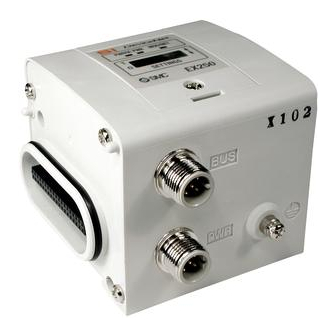
Model Indication and How to Order EX250-SCF1-X200 Special product Communication protocol CC-Link IE Field Summary of Product elements Element Description Communication connector (PORT1 (P1)) 1 Connect with CC-Link IE Field communication line. Communication connector (PORT2 (P2)) Supplies power to the solenoid valve, the output block, SI unit and the input Power supply connector 1... -
Page 10: Mounting And Installation
Mounting and Installation ■Wiring ○Power supply wiring Power supply line inside the SI unit has individual power supplies for solenoid valve actuation (SV power supply) and for control parts and input block (SW power supply). Supply 24 VDC for each of them. : In case of single power supply, pay attention to the range of each supply voltage. - Page 11 ○Ground terminal Connect the ground terminal to ground. Resistance to ground should be 100 ohms or less. -10- No.EX※※-OMU1012...
- Page 12 ○Communication connector PORT1 (P1)/PORT2 (P2): M12 8pin socket X-Coding (CAT5e or more) Description Function TRD+ (0) Data 0 is sent and received. (+) TRD- (0) Data 0 is sent and received. (-) TRD+ (1) Data 1 is sent and received. (+) TRD- (1) Data 1 is sent and received.
- Page 13 ○Maintenance Addition of input block •Remove the screws from the end plate to remove the plate. •Mount the additional tie rods (supplied with the input block). •Connect additional input block. •Re-mount the end plate that was removed, and tighten the screws to the specified tightening torque. (0.6 Nm) Replacing the SI unit •Remove the screws from the end plate and release the connection with the valve unit.
-
Page 14: Setting
Setting ○LED indication LED indication LED status Description Normal power supply for solenoids PW(V) (Green) Insufficient power supply for solenoids (19 V or less) Normal power supply for control and input Normal mode Insufficient power supply for control and input (Green) Flickering Test mode... - Page 15 ○Switch setting Station No., Network No. are set by the switch inside of the SI unit cover. Set parameters while the power of SI unit is OFF. The setting of each switches can be fixed after power is •Station number setting Setting Setting range 0 to C...
- Page 16 ○I/O memory map and diagnostic information (1) Occupation point of device parameter Device type Device name Occupation size 32 points Remote input 32 points Remote output Remote register 4 words Remote register 4 words -15- No.EX※※-OMU1012...
- Page 17 (2) bit/word Area •bit area Description Description Input signal 0 Output signal 0 Output signal 1 Input signal 1 Output signal 2 Input signal 2 RX1F Input signal 31 RY1F Output signal 31 •word area Details Details RWr0 System input RWw0 Unused RWr1...
- Page 18 ○Output number assignment Combinations of output data and valve manifold : The output numbering refers to the solenoid position on the manifold and starts at zero. : Standard wiring of the manifold is for double-solenoid valves and the output number starts at the A side and then B side in that order as shown in the figure a.
-
Page 19: Maintenance
Maintenance •Mounting and wiring Item to inspect Criteria Countermeasure Confirm the connectors (communication, power supply) of SI No looseness. Tighten the resistance. unit securely connected. If any error is found on the appearance, Confirm the connecting cable broken. No appearance error replace the cable. -
Page 20: Troubleshooting
Troubleshooting When SI unit does not operate properly, follow the flow chart below and resolve it. SI unit SI unit Refer to fault malfunction PW LED is OFF No.1 SI unit Refer to fault PW(V) LED is OFF No.2 SI unit Refer to fault P1/P2 LINK LED No.3... - Page 21 Failure Problem Fault No.1 Problem Possible cause Investigation method Countermeasures Tighten the power supply cable connection. (If the cable Incorrect wiring of has a broken wire, replace the Check the power supply cable connections the power supply for cable). and check for broken wires. CC-Link IE Field SI unit PW Correct the wiring of the power...
- Page 22 Fault No.5 Problem Possible cause Investigation method Countermeasures Out of node number Check if the node number is outside of the Set the node number within setting range node number setting range. the setting range. Node number Set the node number so that it Check if the node number is duplicated.
-
Page 23: Specification
Specification ■Specifications General specification Item Specifications Ambient temperature -10 to 50 Ambient humidity 35 to 85% RH (no condensation) Storage temperature -20 to 60 Withstand voltage 500 VAC applied for 1 minute 500 VDC, 10 MΩ or more Insulation resistance Operating atmosphere No corrosive gas Enclosure... - Page 24 1: Applicable block Part number Remarks EX250-IE1 M12 connector, 2 inputs Input block EX250-IE2 M12 connector, 4 inputs EX250-IE3 M12 connector, 2 inputs 2 EX9-OET1 M12 connector, 2 outputs, source / PNP (negative common) low wattage load Output EX9-OEP1 M12 connector, 2 outputs, source / PNP (negative common) high wattage load component 2 EX9-PE1...
-
Page 25: Dimensions
■Dimensions -24- No.EX※※-OMU1012... -
Page 26: Option
Option 1. Power supply cable 6.4 Cable outer diameter Wire gauge 0.3 mm /AWG22 Wire outer diameter 1.65 mm Minimum bending radius 40 mm (Fixed) 2. End plate (Input block side) EX250-EA1 EX250-EA2 3. End Plate R (Output side) EX9-EA03 EX9-EA04 -25- No.EX※※-OMU1012... - Page 27 4. Waterproof cap Mounted on the unused ports of the Input block, Output block and Power block. Proper use of this waterproof cap can achieve IP67 enclosure. (The waterproof caps are delivered together with the Power block as accessories.) Note Tighten the waterproof cap with the specified tightening torque.
- Page 28 Revision history 4-14-1, Sotokanda, Chiyoda-ku, Tokyo 101-0021 JAPAN Tel: + 81 3 5207 8249 Fax: +81 3 5298 5362 http://www.smcworld.com Note: Specifications are subject to change without prior notice and any obligation on the part of the manufacturer. © 2016 SMC Corporation All Rights Reserved. No.EX※※-OMU1012...
Need help?
Do you have a question about the EX250-SCF1-X200 and is the answer not in the manual?
Questions and answers