
Subscribe to Our Youtube Channel
Related Manuals for SMC Networks EX260-SEN2-X205


Summary of Contents for SMC Networks EX260-SEN2-X205
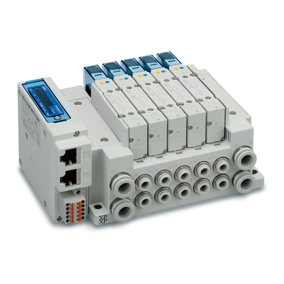
- Page 1 No.EX※※-OMX1001 PRODUCT NAME SI unit for EtherNet/IP MODEL / Series / Product Number EX260-SEN2-X205...
-
Page 2: Table Of Contents
Table of Contents Safety Instructions Model Indication and How to Order Summary of Product parts Definition and terminology Installation and Wiring Installation Wiring LED Indication and Settings Hardware Configuration EDS file and icon Setting using RSLogix5000 Setting using Network Configurator EtherNet/IP Device Level Ring (DLR) function EtherNet/IP... -
Page 3: Safety Instructions
Safety Instructions These safety instructions are intended to prevent hazardous situations and/or equipment damage. These instructions indicate the level of potential hazard with the labels of "Caution", "Warning" or "Danger". They are all important notes for safety and must be followed in addition to International Standards (ISO/IEC) , and other safety regulations. - Page 4 Safety Instructions Caution 1.The product is provided for use in manufacturing industries. The product herein described is basically provided for peaceful use in manufacturing industries. If considering using the product in other industries, consult SMC beforehand and exchange specifications or a contract if necessary. If anything is unclear, contact your nearest sales branch.
- Page 5 Operator This operation manual is intended for those who have knowledge of machinery using pneumatic equipment, and have sufficient knowledge of assembly, operation and maintenance of such equipment. Only those persons are allowed to perform assembly, operation and maintenance. Read and understand this operation manual carefully before assembling, operating or providing maintenance to the product.
- Page 6 ■NOTE ○Follow the instructions given below when designing, selecting and handling the product. The instructions on design and selection (installation, wiring, environment, adjustment, operation, described below must also be followed. maintenance, etc.) Product specifications •When conformity to UL is required, the SI unit should be used with a UL1310 Class 2 power supply. •The SI unit is a "UL"...
- Page 7 Product handling Installation •Do not drop, hit or apply excessive shock to the fieldbus system. Otherwise damage to the product can result, causing malfunction. •Tighten to the specified tightening torque. If the tightening torque is exceeded the mounting screws may be broken. IP67 protection cannot be guaranteed if the screws are not tightened to the specified torque.
- Page 8 •Mount the product in a place that is not exposed to vibration or impact. Otherwise failure or malfunction can result. •Do not use the product in an environment that is exposed to temperature cycle. Heat cycles other than ordinary changes in temperature can adversely affect the inside of the product. •Do not expose the product to direct sunlight.
-
Page 9: Model Indication And How To Order
Model Indication and How to Order EX260-SEN 2 -X205 Output specification 32 outputs, NPN (positive common)/sink Fieldbus EtherNet/IP No.EX※※-OMX1001... -
Page 10: Summary Of Product Parts
Summary of Product parts Element Description Fieldbus interface connector EtherNet/IP connection. (BUS OUT) (BUS OUT) (RJ45 connector) Fieldbus interface connector EtherNet/IP connection. (BUS IN) (BUS IN) (RJ45 connector) Power supply connector Power supply with load voltage for valves and operating voltage for SI unit. Output connector Output signal interface for valve manifold. -
Page 11: Definition And Terminology
■Definition and terminology Terms Meaning 100BASE-TX Standard of LAN transmission line with communication speed of 100 Mbps. The signal from the analogue input device is converted to digital, and displayed in AD value decimal and hexadecimal. These hexadecimal and decimal values are also outputted to the analogue output device. -
Page 12: Installation And Wiring
Installation and Wiring ■Installation Connect valve manifold to the SI unit. •Dimensions for installation n: number of valve stations 120.7 136.7 152.7 168.7 184.7 200.7 216.7 232.7 248.7 264.7 280.7 296.7 312.7 328.7 344.7 (mm) The above table shows dimensions as an example for the SY5000 series valve manifold. Refer to the valve manifold section in the valve catalogue for valve manifold dimensions. -
Page 13: Wiring
■Wiring Select the appropriate cables to mate with the connectors mounted on the SI unit. ○Fieldbus interface connector layout BUS OUT: RJ45 8-pin socket Designation Description Transmit Data + Transmit Data - Receive Data + Receive Data - BUS IN: RJ45 8-pin socket Designation Description Transmit Data +... - Page 14 ○Power supply connector layout PWR: 5-pin socket Designation Description Function earth 0 V for solenoid valve 24 V +24 V for solenoid valve 0 V for SI unit operation +24 V for SI unit operation The power supply connector included as an accessory can be used to supply the power. Applicable wire for the power supply connector is AWG24 to AWG16 (0.2 to 1.5 mm Tighten the connector flange with a tightening torque of 0.2 to 0.3 Nm.
- Page 15 Power-supply line for solenoid valve and power-supply line for SI unit operation are isolated. Be sure to supply power, respectively. Either single-source power or two different power supplies can be used. : Pay attention not to exceed the tolerance range of power supply voltage. -14- No.EX※※-OMX1001...
- Page 16 ○Ground terminal Connect the ground terminal to ground. Resistance to ground should be 100 ohms or less. -15- No.EX※※-OMX1001...
-
Page 17: Led Indication And Settings
LED Indication and Settings ○LED indication LED Status Description The SI unit operating voltage is not supplied or the IP address is not set. Green ON EtherNet/IP communications established. Green flashing EtherNet/IP communications not established. Red flashing EtherNet/IP communications time out. Red ON IP address duplicated. - Page 18 ○Switch setting The switches should only be set with the power supply turned off. Open the cover and set the rotary switches and DIP switch with a small flat blade screwdriver. -17- No.EX※※-OMX1001...
- Page 19 1: Remote control (IP Address X switch set to 000) The mode to respond to the following commands of the BOOTP/DHCP Server, supplied by Rockwell Automation. When receiving the IP address from the BOOTP/DHCP Server, please check the following points: •The communication cable is not connected to the master unit.
-
Page 20: Hardware Configuration
Product number File name Contents (EDS file and icon) EX260-SEN2-X205 ex260_sen2_x205_24_v.zip ex260_sen2_x205_24_v.eds, ex260-sen2-x205.ico ■Setting using RSLogix5000 The method of connecting the SI unit with a Rockwell Automation EtherNet/IP (master) module is shown below. Refer to the RSLogix5000 manual for further details. - Page 21 •The Select Module Type screen will be displayed. Select [ETHERNET MODULE Generic Ethernet Module] and click on Create. -20- No.EX※※-OMX1001...
- Page 22 •The Module Properties screen will be displayed. Perform the various settings. (1) Name: Input a unit name of your choice. (2) Comm Format: Select the data format of the Connection Parameters. (3) IP Address: Input the IP Address of the SI unit. (4) Assembly Instance: Set as follows: Input = 100...
- Page 23 ○Setting using the EDS file •Install in advance the EDS file using the Rockwell Automation software RSNetWorx for EtherNet/IP Refer to the Manual for RSNetWorx for EtherNet/IP for installation instructions. : RSNetWorx is a trademark of Rockwell Automation. When the EDS file is installed, the SI unit number will be added in the Select Module screen. Select the SI unit number to be used, and click the Create button.
- Page 24 •The Module Properties screen is displayed. Perform each setting. (1) Name: Enter the desired unit name. (2) IP Address: Enter the IP address that was set for the SI unit. -23- No.EX※※-OMX1001...
-
Page 25: Setting Using Network Configurator
■Setting using Network Configurator Method to connect the SI unit to the OMRON EtherNet/IP module (master) is shown below. Refer to the Operation Manual of the Network Configurator for the detailed operation. : The drawing below shows the OMRONS software, Network Configurator. It is necessary to install the EDS file for the Network Configurator. - Page 26 •Double-click on the icon of the master to open the Edit Device Parameter window, and move the SI unit from the [Unregister Device List] to the [Register Device List]. -25- No.EX※※-OMX1001...
- Page 27 •Double click on the SI unit in the [Register Device List] to open the Edit Connection screen. For [Connection I/O Type], select [Exclusive Owner]. For the Originator Device, select an arbitrary [Input Tag Set] and [Output Tag Set], with the same number of bytes as the [Output Tag Set] and [Input Tag Set] in the Target Device, and register the Input/Output connection.
- Page 28 Example: Tag Set D00100 (2 bytes) to the Input, and D00150 (4 bytes) to the Output. -27- No.EX※※-OMX1001...
- Page 29 •If the allocation has been correctly completed, the registered IP address will be displayed with the SI unit icon in the network window. -28- No.EX※※-OMX1001...
-
Page 30: Ethernet/Ip Tm Device Level Ring (Dlr) Function
■EtherNet/IP Device Level Ring (DLR) function This SI unit can be used as an EtherNet/IP compliant node for network rings with the DLR function. To enable the DLR function, all the ring nodes need to be applicable to the DLR function. Since all of the DLR function settings are performed by the Ring Supervisor, there is no need to perform any settings to the SI unit. - Page 31 ○Output number assignment Output data : The output numbering refers to the solenoid position on the manifold and starts at zero. : Standard wiring of the manifold is for double-solenoid valves and the output number starts at the A side and then B side in that order as shown in the figure a.
-
Page 32: Web Server Function
■Web server function The SI unit has a Web server function which allows checking the information of the unit information from a PC Web browser during maintenance, or checking of I/O monitor or forced output of ON/OFF of the valve. •Connection of SI unit and PC Connect SI unit and PC to the same Ethernet network, then start the Web browser on the PC. - Page 33 •Web server contents Web browser screen when the Web server is connected is shown below. <I/O Status tab> Current SI unit I/O memory map is displayed. Refer to page for I/O memory map details. ① ② ③ ④ ⑤ ⑦ ⑥...
- Page 34 •Forced output mode Procedure to change to forced output more and the method of forced output. Warning and password input screen will appear by selecting the Force output button. Force output space becomes active when the password entered is successful. The mode will be changed to force output mode.
- Page 35 OUTPUT DATA becomes editable in forced output mode. Edited OUTPUT DATA is displayed in red. After OUTPUT DATA is edited, the output data will be reflected by selecting "Execute". Reflected OUTPUT DATA is displayed in yellow. All output data can be cleared by selecting “Reset”. Forced output mode is released by selecting “Force output exit“.
- Page 36 •Password change Password can be changed by selecting the Change password button. Type the password before change in the Old password space, and the new password in the New password and Confirm password spaces. Password change is completed by selecting OK. <CAUTION>...
- Page 37 <Properties tab> Network information including the SI unit MAC address and communication speed are displayed. <Performance tab> The EtherNet performance of the SI unit is displayed. -36- No.EX※※-OMX1001...
- Page 38 <Diagnostic tab> The communication status of the SI unit is displayed. <Config tab> The EtherNet/IP QuickConnect of the SI unit can be set using the Config tab. Similarly, it can be set using the [QuickConnect ] function of the EtherNet/IP (page 29).
-
Page 39: Troubleshooting And Maintenance
Troubleshooting and Maintenance ○Troubleshooting chart When any malfunction is observed, it is recommended to perform the following troubleshooting. Refer to fault SI unit SI unit MS LED is No.1 malfunction Refer to fault SI unit PWR(V) LED No.2 is OFF Refer to fault SI unit L/A LED is No.3... - Page 40 Troubleshooting table Fault No.1 Fault Probable cause Recommended error handling Recommended action Re-tighten the power cable. (Replace the cable if it is Defective power Check the condition of the power cable SI unit broken) cable wiring for SI wiring to the SI unit. MS LED is unit operation Correct the power cable wiring...
- Page 41 Fault No.6 Fault Probable cause Recommended error handling Recommended action Set the configuration properly. Configuration is not Refer to "Hardware Configuration" (page 19) Check the PLC configuration. correctly SI unit for details. MS LED is Refer to the master device green flashing The master is idle Set the PLC to RUN status.
- Page 42 Fault No.11 Fault Probable cause Recommended error handling Recommended action Tighten the screws with the Poor connection Check if there are any loose screws making specified tightening torque between SI unit and the connection between the SI unit and the (i.e.
- Page 43 ○Maintenance Replacement of the SI unit •Remove the M3 hexagon screws from the SI unit and release the SI unit from the valve manifold. •Replace the SI unit. •Tighten the screws with the specified tightening torque. (0.6 Nm) Precautions for maintenance (1) Be sure to switch off the power.
-
Page 44: Specifications
Specifications General specifications Item Specifications Ambient temperature -10 to +50 Ambient humidity 35 to 85%RH (No condensate) Ambient temperature for storage -20 to +60 Withstand voltage 500 VAC applied for 1 minute Insulation resistance 500 VDC, 10 MΩ or more Operating atmosphere No corrosive gas 1... - Page 45 Communication specifications Item Specifications Protocol Ethernet (IEEE802.3) Standard Ethernet cable (CAT5 or more) Transmission medium (100BASE-TX) Transmission speed 10 Mbps/100 Mbps (Auto negotiation) Transmission method Full duplex/Half duplex (Auto negotiation) EtherNet/IP Fieldbus protocol Volume1 (Edition 3.25) Volume2 (Edition 1.23) Vendor ID 7h (SMC Corporation) Product type 1Bh (Pneumatic Valve)
- Page 46 ○I/O Mapping Input area mapping Input data Offset (Word) SOLV L: Low fixed (0) Input status area Input status area specifications Item Status State Normal SOLV State of power supply for solenoid valve Abnormal (19 V or less) Output area mapping Output data Offset (Word)
-
Page 47: Dimensions
■Dimensions -46- No.EX※※-OMX1001... - Page 48 Revision history 4-14-1, Sotokanda, Chiyoda-ku, Tokyo 101-0021 JAPAN Tel: + 81 3 5207 8249 Fax: +81 3 5298 5362 https://www.smcworld.com Note: Specifications are subject to change without prior notice and any obligation on the part of the manufacturer. EtherNet/IP is a trademark of ODVA. QuickConnect is a trademark of ODVA.
Need help?
Do you have a question about the EX260-SEN2-X205 and is the answer not in the manual?
Questions and answers