Table of Contents
Advertisement
Quick Links
Before Use
Fieldbus device
EX250 SAS3/EX250 SAS5
EX250 SAS7/EX250 SAS9
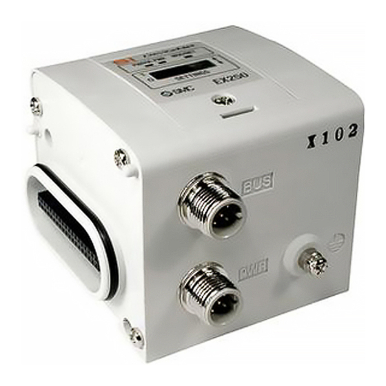
Thank you for purchasing an SMC EX250-SAS3/EX250-SAS5/EX250-SAS7/
EX250-SAS9 Fieldbus device.
Please read this manual carefully before operating the product and make sure you
understand its capabilities and limitations. Please keep this manual handy for
future reference.
To obtain the operation manual about this product and
control unit, please refer to the SMC website
(URL http://www.smcworld.com) or contact SMC directly.
Safety Instructions
These safety instructions are intended to prevent hazardous situations and/or
equipment damage.
These instructions indicate the level of potential hazard with the labels of
"Caution", " Warning" or "Danger". They are all important notes for safety and
must be followed in addition to International standards (ISO/IEC) and other safety
regulations.
Caution:
CAUTION indicates a hazard with a low level of risk which, if
not avoided, could result in minor or moderate injury.
Warning:
WARNING indicates a hazard with a medium level of risk
which, if not avoided, could result in death or serious injury.
Danger:
DANGER indicates a hazard with a high level of risk which, if
not avoided, will result in death or serious injury.
Operator
This operation manual is intended for those who have knowledge of machinery
using pneumatic equipment, and have sufficient knowledge of assembly,
operation and maintenace of such equipment. Only those persons are allowed
to perform assembly, operation and maintenance.
Read and understand this operation manual carefully before assembling,
operating or providing maintenance to the product.
Safety Instructions
Warning
Do not disassemble, modify (including changing the printed circuit board) or repair.
An injury or failure can result.
Do not operate the product outside of the specifications.
Do not use for flammable or harmful fluids.
Fire, malfunction, or damage to the product can result.
Verify the specifications before use.
Do not operate in an atmosphere containing flammable or explosive gases.
Fire or an explosion can result.
This product is not designed to be explosion proof.
If using the product in an interlocking circuit:
•Provide a double interlocking system, for example a mechanical system.
•Check the product regularly for proper operation.
Otherwise malfunction can result, causing an accident.
The following instructions must be followed during maintenance:
•Turn off the power supply.
•Stop the air supply, exhaust the residual pressure and verify that the air is released before performing
maintenance.
Otherwise an injury can result.
Caution
After maintenance is complete, perform appropriate functional inspections.
Stop operation if the equipment does not function properly.
Safety cannot be assured in the case of unexpected malfunction.
Provide grounding to assure the noise resistance of the product.
Individual grounding should be provided close to the product with a short cable.
NOTE
•When conformity to UL is necessary the SI unit must be used with a UL1310
Class 2 power supply.
•The product is a UL approved product only if it has a
mark on the body.
Summary of Product elements
5
6
1
Tie-rod (2 pcs.)
2
4
Accessory
3
7
No.
Element
Description
1
Communication connector
Connect with AS-Interface communication line.
Power supply connector for
2
Supplies power to the solenoid valve and Output block.
output equipment
1
3
Input block connector
Connects the Input block.
4
Output block connector
Connects the solenoid valve, Output block and etc.
5
Display window
LED display shows the SI unit status.
6
Switch protective cover
Sets the address and baud rate etc. with the switch inside.
7
Grounding terminal (FE)
1
Used for grounding.
1: Available only for EX250-SAS3/EX250-SAS5.
Mounting and Installation
Installation
The SI unit does not have mounting holes, so it cannot be installed alone. Make sure to
connect the valve manifold.
Refer to the valve catalogue for valve manifold dimensions.
Assembly and disassembly of the SI unit
M3 hexagon screw
Tie-rod
Tightening torque: 0.6 Nm
Tightening torque: 0.6 Nm
End plate
SI unit
Valve manifold
Exchange of SI unit
•Remove screws from End Plate and release connection of each unit.
•Replace old SI unit with new one. (Tie-rod does not need to be removed.)
•Connect Input Block and End Plate and tighten removed screws by specified
tightening torque. (0.6 Nm)
Assembly and disconnection of unit
Addition of Input Block
•Remove screws from End Plate.
•Mount attached tie-rod.
•Connect additional Input Block.
•Connect End Plate and tighten removed screws by specified tightening torque.
(0.6 Nm)
Caution for maintenance
(1) Be sure to turn-off all power supplies.
(2) Be sure that there is no foreign object in any of units.
(3) Be sure that gasket is lined properly.
(4) Be sure that tightening torque is according to specification.
If these items are not kept, it may lead to the breakage of substrate or intrusion of
liquid or dust into the units.
Connecting cables
Select the appropriate cables to mate with the connectors mounted on the SI unit.
EX250-SAS3/EX250-SAS5
•Communication connector
M12 4-pin plug
No.
Description
Function
1
1
AS-i +
AS−Interface line (+)
2
4
2
(0 V)
Power supply for output equipment (-)
3
3
AS-i -
AS−Interface line (-)
4
(24 V)
Power supply for output equipment (+)
•Power supply connector for output equipment
M12 4-pin plug
No.
Description
Function
1
1
24 V
Power supply for output equipment (+)
2
4
2
N.C.
Unused
3
3
0 V
Power supply for output equipment (-)
4
N.C.
Unused
: Connected inside the SI unit.
Communication connector
Ground terminal
Power supply connector
for output equipment
•Connection example
M12 cable
Recommendation conductor cross-section: 1.5mm
2
AS-i standard cable
EX250-SAS3
(YELLOW CABLE)
AS-i standard cable
Connector for T-branch
(BLACK CABLE)
ASI FK M12 Hirschmann etc.
(IEC 603526)
The M12 cable, AS-i standard cable and connector for T-branch are not supplied by SMC.
Contact each manufacturer for the catalogue details etc.
Wire the cable for AS-Interface line so that the total voltage drop is 3 V or less.
EX250-SAS7/EX250-SAS9
•Communication connector
M12 4-pin, plug
No.
Description
Function
1
1
AS−Interface line (+)
2
4
2
(0 V)
RESERVE
3
3
AS-i -
AS−Interface line (-)
4
(24 V)
RESERVE
Communication connector
•Connection example
M12 cable
Recommendation conductor cross-section: 1.5mm
2
AS-i standard cable
EX250-SAS7
(YELLOW CABLE)
Connector for T-branch
ASI FK M12 Hirschmann etc.
(IEC 603526)
The M12 cable, AS-i standard cable and connector for T-branch are not supplied by SMC.
Contact each manufacturer for the catalogue details etc.
Wire the cable for AS-Interface line so that the total voltage drop is 3 V or less.
Setting
Address setting
HOLD/CLEAR setting
Over Current Protection setting SW
Address setting procedure via the AS-i line
To set this function, refer to SMC website (URL http://www.smcworld.com) for more detailed
information or contact us.
LED Indication
SI
CLEAR
IN
COM
SW
PWR
AUX
-ERR
-ERR
HOLD
ADDRESS SETTING
ADDR1
ADDR2
EX250
Description
LED
LED condition
EX250-SAS3/EX250-SAS5
EX250-SAS7/EX250-SAS9
PWR
Green LED is ON
Indicates that the power supply for AS-Interface line is turned ON.
Indicates that the power supply for
-
AUX
Green LED is ON
output equipment is turned ON.
(LED is OFF at normal condition)
Indicates that an input power supply over current is detected.
IN-ERR
Red LED is ON
(LED is OFF at normal condition)
Indicates a communication error.
Red LED is ON
(LED is OFF at normal condition)
COM-ERR
Indicates peripheral equipment error.
1
Red LED is flashing
(Over current of input power, blown fuse)
1: EX250-SAS3/EX250-SAS5: Input block
EX250-SAS7/EX250-SAS9: Input block, Output block, Solenoid valve
Troubleshooting
Technical documentation giving detailed troubleshooting information can be found on the
SMC website (URL http://www.smcworld.com).
Specifications
Connected load: 24 VDC Solenoid valve with surge voltage suppressor of 1.5 W or less
(manufactured by SMC)
Current consumption of power supply for SI unit operation: 0.1 A max.
Operating ambient temp.: +5 to +45
o
C
Storage ambient temp.: -20 to +60
C
o
1: Input terminal are not isolated from Power source.
2: Do not connect outside Power source to Input and Output terminals.
Technical documentation giving detailed specification information can be found on the SMC
website (URL http://www.smcworld.com).
Outline Dimensions
Technical documentation giving detailed outline dimensions information can be found on
the SMC website (URL http://www.smcworld.com).
URL http://www.smcworld.com
Akihabara UDX 15F, 4-14-1, Sotokanda, Chiyoda-ku, Tokyo 101-0021, JAPAN
Phone: +81 3-5207-8249 Fax: +81 3-5298-5362
Note: Specifications are subject to change without prior notice and any obligation on the part of the manufacturer.
© 2012-2017 SMC Corporation All Rights Reserved.
1
EX※※-OMP0021-A
Advertisement
Table of Contents

Related Manuals for SMC Networks EX250-SAS7


Summary of Contents for SMC Networks EX250-SAS7
- Page 1 To set this function, refer to SMC website (URL http://www.smcworld.com) for more detailed AS-i + AS−Interface line (+) information or contact us. Thank you for purchasing an SMC EX250-SAS3/EX250-SAS5/EX250-SAS7/ (0 V) Power supply for output equipment (-) EX250-SAS9 Fieldbus device.
- Page 2 No.EX※※-OMP0025-A PRODUCT NAME SI unit for AS-Interface MODEL / Series / Product Number EX250-SAS#...
-
Page 3: Table Of Contents
Table of Contents Safety Instructions Product Outline Model Indication and How to Order Summary of Product elements Mounting and Installation Installation Wiring Setting Indication Connection between SI unit output and the solenoid valve Data bit Maintenance Troubleshooting Specifications Specifications Dimensions No.EX※※-OMP0025-A... -
Page 4: Safety Instructions
Safety Instructions These safety instructions are intended to prevent hazardous situations and/or equipment damage. These instructions indicate the level of potential hazard with the labels of "Caution", "Warning" or "Danger". They are all important notes for safety and must be followed in addition to International 1) standards (ISO/IEC) and other safety regulations. - Page 5 Caution The product is provided for use in manufacturing industries. The product herein described is basically provided for peaceful use in manufacturing industries. If considering using the product in other industries, consult SMC beforehand and exchange specifications or a contract if necessary. If anything is unclear, contact your nearest sales branch.
- Page 6 Operator This operation manual is intended for those who have knowledge of machinery using pneumatic equipment, and have sufficient knowledge of assembly, operation and maintenance of such equipment. Only those persons are allowed to perform assembly, operation and maintenance. Read and understand this operation manual carefully before assembling, operating or providing maintenance to the product.
- Page 7 ■NOTE ○Follow the instructions given below when designing, selecting and handling the product. The instructions on design and selection (installation, wiring, environment, adjustment, operation, described below must also be followed. maintenance, etc.) Product specifications •When conformity to UL is necessary the SI unit must be used with a UL1310 Class2 power supply. •The SI unit is a UL approved product only if they have a mark on the body.
- Page 8 Product handling Installation •Do not drop, hit or apply excessive shock to the fieldbus system. Otherwise damage to the product can result, causing malfunction. •Tighten to the specified tightening torque. If the tightening torque is exceeded the mounting screws may be broken. IP67 protection cannot be guaranteed if the screws are not tightened to the specified torque.
- Page 9 •Mount the product in a place that is not exposed to vibration or impact. Otherwise failure or malfunction can result. •Do not use the product in an environment that is exposed to temperature cycle. Heat cycles other than ordinary changes in temperature can adversely affect the inside of the product. •Do not expose the product to direct sunlight.
-
Page 10: Product Outline
Product Outline System configuration This system connects input/output devices to AS-Interface with reduced wiring. AS-Interface communicates with the input/output devices via the SI unit. Input blocks, EX9 series output blocks and valve manifolds can be connected. 1: Refer to the operation manual EX250-IE1 / -IE2 / -IE3 for the input block specifications, and EX9-OET1 / -OET2 / -OEP1 / -OEP2 / -PE1 for the output block and power block specifications. -
Page 11: Model Indication And How To Order
Model Indication and How to Order EX250-S AS 3 Input / output and power supply PNP (negative common) / source, 8 inputs / 8 outputs, 2 power supply systems PNP (negative common) / source, 4 inputs / 4 outputs, 2 power supply systems PNP (negative common) / source, 8 inputs / 8 outputs, 1 power supply system PNP (negative common) / source, 4 inputs / 4 outputs, 1 power supply system Communication protocol... -
Page 12: Mounting And Installation
Mounting and Installation ■Installation The SI unit does not have mounting holes, so it cannot be installed alone. Make sure to connect the solenoid valve. When an input block is not required, connect the end plate directly to the SI unit. ○Installation example Dimensions when VQC2000 series solenoid valve manifold is connected are shown in the table below for reference. -
Page 13: Wiring
■Wiring ○The topology of an AS-i network The topology of an AS-i network can be connected as a tree, a line or point to point. The maximum total length of the cable must be 100 m. It is possible to extend the total length of the cable up to 300 m by using a repeater. -11- No.EX※※-OMP0025-A... - Page 14 ○Wiring •EX250-SAS3/-SAS5 Communication connector: M12 4-pin, plug Description Function AS-i + ASInterface line (+) (0 V) (Power supply for output equipment (-)) AS-i - ASInterface line (-) (24 V) (Power supply for output equipment (+)) Power supply connector for output equipment: M12 4-pin, plug ...
- Page 15 •EX250-SAS7/-SAS9 Communication connector: M12 4-pin, plug Description Function AS-i + ASInterface line (+) RESERVE RESERVE AS-i - ASInterface line (-) RESERVE RESERVE •Connection example The M12 cable, AS-i standard cable and connector for T-branch are not supplied by SMC. Contact each manufacturer for the catalogue details etc.
-
Page 16: Setting
Setting ○Address setting The AS-I cable line should be disconnected from the SI unit while setting the address. Open the cover and set the address using an AS-Interface address programming device and DC power jack cable etc. (PEPPERL + FUCHS: VAZ-PK-V1-Cinch, SIEMENS: 3RK1901-3HA00 etc.) The Address assignment range is 1 to 31. - Page 17 ○Address setting procedure via the AS-i line The following is the procedure for address setting of the master unit via the AS-i line with EX250-SAS3/-SAS7 (8 inputs / 8 outputs, and address connector – 2 pcs.). For setting the unit which occupies two slaves (EX250-SAS3/-SAS7), plug the cable jack into the address which is not to be set (ADDR2 when ADDR1 is set) to disconnect the address from the AS-i line.
-
Page 18: Indication
Red LED is ON (LED is OFF at normal condition) COM-ERR 1 Indicates peripheral equipment error. Red LED is flashing (Over current of input power, blown fuse) 1: EX250-SAS3/-SAS5: Input block EX250-SAS7/-SAS9: Input block, Output block, Solenoid valve -16- No.EX※※-OMP0025-A... -
Page 19: Connection Between Si Unit Output And The Solenoid Valve
Connection between SI unit output and the solenoid valve ○Standard wiring The outputs of the SI unit are assigned from the D side solenoid valve in the order 0, 1, 2 … etc. Refer to each solenoid valve’s catalogue for details. •Standard Address Mode (EX250-SAS3/-SAS7, EX250-IE3, Manifold standard wiring, Double solenoid wiring) ○Special wiring... -
Page 20: Data Bit
Data bit •SI unit input/output data bit Address Data bit EX250-SAS3/-SAS7 EX250-SAS5/-SAS9 IN0 / OUT0 IN0 / OUT0 IN1 / OUT1 IN1 / OUT1 ADDR1 IN2 / OUT2 IN2 / OUT2 IN3 / OUT3 IN3 / OUT3 IN4 / OUT4 IN5 / OUT5 ADDR2 IN6 / OUT6... -
Page 21: Maintenance
Maintenance Addition of input block •Remove the screws from the end plate to remove the plate. •Mount the additional tie rods (supplied with the input block). •Connect additional input block. •Re-mount the end plate that was removed, and tighten the screws to the specified tightening torque. (0.6 Nm) Replacing the SI unit •Remove the screws from the end plate and release the connection with the valve unit. -
Page 22: Troubleshooting
Troubleshooting Troubleshooting flow chart When any failure occurs with the SI unit, the following chart can be used to identify the cause of the failure. SI unit does not SI unit PWR LED Refer to fault operate normally. is OFF. No.1 SI unit AUX LED is OFF. - Page 23 Output block does not Check the state of Refer to fault operate correctly. the output block. No.9 Output block LED is OFF. Output block does not Refer to fault operate correctly. No.10 Output block LED is ON. Only the input Input device data Refer to fault cannot be...
- Page 24 Troubleshooting Fault No.1 Problem Possible cause Investigation method Countermeasures Correct the AS-i cable connection. (Replace the AS-i line power supply Check the AS-i cable connections and check cable if it is broken.) wiring failure for broken wires. Correct the wiring of the AS-i SI unit PWR cable.
- Page 25 Over current to the Check the supply current to the input block Correct the supply current to LED red is power supply of •EX250-SAS7/-SAS9 within the specification flashing, input/output block Check the supply current to the input block, range. (See page 27)
- Page 26 Fault No.9 Problem Possible cause Investigation method Countermeasures Defective connection Confirm grounding to Check that the screws which connect the SI between the SI unit improve the anti-noise unit and output block are not loose. and output block performance of the SI unit. Polarity of the output Check that the output block polarity Use an output block polarity...
- Page 27 Fault No.12 Problem Possible cause Investigation method Countermeasures Tighten the screws while holding the SI unit and the Defective connection input block so that there is Check that the screws which connect the SI between the SI unit no gap between them. unit and input block are not loose.
-
Page 28: Specifications
Specifications ■Specifications General specification Item Specifications Ambient temperature 5 to 45 Ambient humidity 35 to 85%RH (no condensation) Storage temperature -20 to +60 Withstand voltage 500 VAC, 1 minute, Between whole external and FG Insulation resistance 500 VDC, 10 MΩ or more, Between whole external and FG Operating atmosphere No corrosive gas or dust Pollution degree... - Page 29 Electrical specifications Specifications Item EX250-SAS3 EX250-SAS5 EX250-SAS7 EX250-SAS9 1 For communication Supplied by AS-Interface circuit. 26.5 to 31.6 VDC Power supply 2 voltage For output 24 VDC +10%/-5%, PELV 3 Internal current consumption (Unit) 100 mA or less...
-
Page 30: Dimensions
■Dimensions ○EX250-SAS3/-SAS5 -28- No.EX※※-OMP0025-A... - Page 31 ○EX250-SAS7/-SAS9 -29- No.EX※※-OMP0025-A...
- Page 32 Revision history A: Limited warranty and Disclaimer are added. Note: Specifications are subject to change without prior notice and any obligation on the part of the manufacturer. © 2012-2013 SMC Corporation All Rights Reserved No.EX※※-OMP0025-A...
Need help?
Do you have a question about the EX250-SAS7 and is the answer not in the manual?
Questions and answers